EP0080947A1 - Sperrvorrichtung für Differentialgetriebe - Google Patents
Sperrvorrichtung für Differentialgetriebe Download PDFInfo
- Publication number
- EP0080947A1 EP0080947A1 EP82402156A EP82402156A EP0080947A1 EP 0080947 A1 EP0080947 A1 EP 0080947A1 EP 82402156 A EP82402156 A EP 82402156A EP 82402156 A EP82402156 A EP 82402156A EP 0080947 A1 EP0080947 A1 EP 0080947A1
- Authority
- EP
- European Patent Office
- Prior art keywords
- differential
- segment
- friction
- lug
- bore
- Prior art date
- Legal status (The legal status is an assumption and is not a legal conclusion. Google has not performed a legal analysis and makes no representation as to the accuracy of the status listed.)
- Granted
Links
Images

Classifications
-
- F—MECHANICAL ENGINEERING; LIGHTING; HEATING; WEAPONS; BLASTING
- F16—ENGINEERING ELEMENTS AND UNITS; GENERAL MEASURES FOR PRODUCING AND MAINTAINING EFFECTIVE FUNCTIONING OF MACHINES OR INSTALLATIONS; THERMAL INSULATION IN GENERAL
- F16H—GEARING
- F16H48/00—Differential gearings
- F16H48/20—Arrangements for suppressing or influencing the differential action, e.g. locking devices
- F16H48/22—Arrangements for suppressing or influencing the differential action, e.g. locking devices using friction clutches or brakes
-
- F—MECHANICAL ENGINEERING; LIGHTING; HEATING; WEAPONS; BLASTING
- F16—ENGINEERING ELEMENTS AND UNITS; GENERAL MEASURES FOR PRODUCING AND MAINTAINING EFFECTIVE FUNCTIONING OF MACHINES OR INSTALLATIONS; THERMAL INSULATION IN GENERAL
- F16H—GEARING
- F16H48/00—Differential gearings
- F16H48/06—Differential gearings with gears having orbital motion
- F16H48/08—Differential gearings with gears having orbital motion comprising bevel gears
-
- F—MECHANICAL ENGINEERING; LIGHTING; HEATING; WEAPONS; BLASTING
- F16—ENGINEERING ELEMENTS AND UNITS; GENERAL MEASURES FOR PRODUCING AND MAINTAINING EFFECTIVE FUNCTIONING OF MACHINES OR INSTALLATIONS; THERMAL INSULATION IN GENERAL
- F16H—GEARING
- F16H48/00—Differential gearings
- F16H48/38—Constructional details
- F16H2048/382—Methods for manufacturing differential gearings
Definitions
- the present invention applies to a device for partially locking the differential of a motor vehicle making it possible to increase the torque transmitted by friction between the left and right wheels of the differential axle when these wheels rotate at different angular speeds and thus reducing the risk of the vehicle slipping due to lack of grip on only one of the drive wheels.
- the conventional differentials generally constituted by a bevel gear train and comprising a box-crown assembly driven by a transmission shaft and carrying axes of satellites and the satellites as well as the two planets each corresponding to a wheel shaft, allow the wheels Right and left drive units receive the same engine torque, while turning at different speeds, for example when cornering. If the wheels on one side of the vehicle no longer have grip due to the condition of the road (ice sheet, mud puddle), the vehicle loses traction due to the runaway of the wheel which lack of grip and the transmission is impacted when the grip is picked up.
- the various partial and automatic differential locking systems commonly used have various drawbacks, including one can cite for systems with friction by axial spacing of the planetary, the variation of the conical distance of the teeth of the differential as a result of the wear of the axial friction means. This generally results in premature wear of the conical teeth of the differential, detrimental to the reliability of the differential itself.
- the other partial differential locking systems are either very complex when they are relatively reliable and consequently have a high cost price, or are too large in size to allow their insertion into a standard type differential.
- One of the aims of the present invention is precisely to avoid the drawbacks which have just been listed and to produce a friction differential locking system which does not produce axial forces on the planet gears and which is simple to produce. and reliable.
- the partial friction locking device of the differential of a motor vehicle by means of a friction means interposed between each of the planet gears of the differential and the wheel drive ring is characterized in that the means friction consists of at least one elastic segment housed and compressed in a bore integral with the differential case and on the wall of which it exerts radial pressure.
- the segment is connected to the sun gear via a lug connected at least in rotation to the corresponding sun gear.
- the lug is carried by an annular part connected in rotation, in particular by splines to the corresponding wheel shaft.
- the lug is carried by an annular part connected in rotation, in particular by grooves, to the corresponding sun gear.
- the lug can be made rigidly secured to the corresponding sun gear by any compact and rapid means such as force engagement in a sun gear bore or welding, in particular by electronic bombardment.
- the shape of the segment is chosen so that the radial pressure which it exerts on the wall of the bore of the differential housing is distributed over its entire periphery both in new condition and in worn condition.
- This radial pressure is determined by the deformation of the segment after it is mounted in the bore and decreases as the wear of the segment which is notably reduced by the fact that the friction surfaces are immersed in the oil of the crankcase. differential.
- the radial pressure exerted by the elasticity of the segment by the outer surface of the segment on the surface of the bore can be reinforced by a self-tightening effect due to friction.
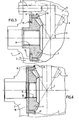
- the differential shown in FIG. 1, of a type used for commercial road vehicles comprises, enclosed in a axle housing not shown, a differential case 1 consisting respectively of a bevel gear 2 whose teeth are not shown are driven in rotation by a bevel gear connected to the engine of the vehicle and a closing flange 3 which carries the axis or axes 4 of the satellites, immobilized by locking screws 5.
- the main elements of the differential are constituted by the play bevel gears 6 of which only one is shown and which mesh on each side of the axle with a sun gear 7 with bevel gear whose inner grooves 8 are engaged with the wheel shaft not shown for driving the wheel of the left side of figure 1.
- an open elastic segment 9 is housed in compression in a bore 10 formed in the flange 3 of the differential housing 1 and a lug 11, formed on the peripheral outer surface of the sun gear 7, engages between the two open faces 12 and 13 of the ends of the segment closed on the lug to connect in rotation with a set of engagement j the segment 9 to the sun gear 7 (see FIG. 2).
- the segment 9 remains practically immobilized in its bore 10 as long as the vehicle is moves in a straight line or in a slight turn at moderate speed because the friction reactions developed between the outer surface of the segment 9 and the bore 10 are opposed to the rotation of the sun gear 7 relative to the differential housing 1.
- the differences in torque between the right and left wheels of the vehicle are sufficient to overcome these friction reactions and the sun gear 7 which previously was content to come and beat with its lug 11 the faces 12 or 13 of the segment at each appearance of a difference in torque between the right and left wheels, is then capable of rotating segment 9 in its bore.
- the rotation of the segment 9 causes a release of heat by friction which is easily evacuated by the oil from the axle housing in which the differential is immersed.
- the segment 9 rotates frictionally in its bore only for limited periods corresponding to the turns taken with a high tangential deceleration and the ability of the vehicle to tackle the turns at high speed is only slightly reduced compared to vehicles of the same type not fitted with partial differential lock.
- the wheel devoid of momentarily of adhesion tends to get carried away under the effect of the rotation of the differential housing 1 by the conical drive pinion of the motor.
- the flange 3 rotates around the segment 9 connected in rotation, by the pin 11, to the sun gear 7 and causes by friction on this segment 9 a drive torque which is transmitted to the wheel which rests on a surface of bearing with higher grip.
- the torque thus transmitted by the segment 9 is generally sufficient to get the vehicle out of the bad patch in which it has engaged.
- the implementation of the differential lock system according to the invention is automatic.
- the lug 11 can come from a forge or foundry with the sun gear 7 or it can be attached by force engagement in a bore of the sun gear or by welding, in particular by electronic bombardment in order to leave intact the physico-chemical structure often hardened and hardened high-strength planetary steel.
- a seqment 9 placed on either one of the two tary nlané- 7 corresponding to the right wheels and oauche enough yard D combine the failure of adhesion of the one or the other of the wheels, but can of course provide for two segments - one on each of the planets - whose effects will be added.
- the single segment 9 which nevertheless constitutes the most practical and compact embodiment of the invention can be replaced by several parallel and / or concentric segments each connected to a lug 11, the lugs 11 of all these segments being able to be distributed over the outer surface of the planet 7.
- the lug 14 ensuring the connection between the sun gear 7 and the segment 9 is carried by an annular part 15 connected in rotation by splines 16 to the sun gear 7.
- the lug 17 for connection between the sun gear 7 and the segment 9 is carried by a thin annular piece 18 connected in rotation by splines 19 to the corresponding wheel shaft itself connected by splines 8 to planetary 7.
- FIGS. 3 and 4 make it possible to avoid attaching the lug to the sun gear 7, the physico-chemical structure of which with high resistance poorly supports the machining or welding operations.
- the arrangement of the annular parts 15 and 18 increases the forces and the friction surfaces between the sun gear 7 and the differential housing 2.
Landscapes
- Engineering & Computer Science (AREA)
- General Engineering & Computer Science (AREA)
- Mechanical Engineering (AREA)
- Retarders (AREA)
Applications Claiming Priority (2)
| Application Number | Priority Date | Filing Date | Title |
|---|---|---|---|
| FR8122364A FR2517403B1 (fr) | 1981-11-30 | 1981-11-30 | Dispositif de blocage de differentiel |
| FR8122364 | 1981-11-30 |
Publications (2)
| Publication Number | Publication Date |
|---|---|
| EP0080947A1 true EP0080947A1 (de) | 1983-06-08 |
| EP0080947B1 EP0080947B1 (de) | 1985-04-17 |
Family
ID=9264488
Family Applications (1)
| Application Number | Title | Priority Date | Filing Date |
|---|---|---|---|
| EP82402156A Expired EP0080947B1 (de) | 1981-11-30 | 1982-11-26 | Sperrvorrichtung für Differentialgetriebe |
Country Status (5)
| Country | Link |
|---|---|
| US (1) | US4811629A (de) |
| EP (1) | EP0080947B1 (de) |
| DE (1) | DE3263169D1 (de) |
| ES (1) | ES517765A0 (de) |
| FR (1) | FR2517403B1 (de) |
Cited By (2)
| Publication number | Priority date | Publication date | Assignee | Title |
|---|---|---|---|---|
| EP0118261A1 (de) * | 1983-03-04 | 1984-09-12 | Eaton Corporation | Kegelräder und damit aufgebaute Getriebe |
| US4811629A (en) * | 1981-11-30 | 1989-03-14 | Renault Vehicules Industriels | Differential locking device |
Families Citing this family (5)
| Publication number | Priority date | Publication date | Assignee | Title |
|---|---|---|---|---|
| US6146304A (en) * | 1998-12-22 | 2000-11-14 | Caterpillar Inc. | Vehicle differential |
| US6432020B1 (en) | 2000-08-10 | 2002-08-13 | Lazaro Rivera | Differential locking assembly |
| US7102245B2 (en) * | 2002-03-21 | 2006-09-05 | Torque-Traction Technologies Llc | Integral generator/pinion assembly for axle power generation |
| WO2015120490A2 (en) * | 2014-01-16 | 2015-08-13 | American Crafts, L.C. | Crafting tool |
| USD742717S1 (en) * | 2014-11-12 | 2015-11-10 | Kevin R. Manning | Differential pin lock |
Citations (9)
| Publication number | Priority date | Publication date | Assignee | Title |
|---|---|---|---|---|
| FR490808A (fr) * | 1918-07-10 | 1919-05-10 | Donald Damon Ormsby | Perfectionnements aux différentiels |
| DE655398C (de) * | 1935-03-30 | 1938-01-14 | Zahnradfabrik Friedrichshafen | Selbstsperrendes Ausgleichgetriebe fuer Bodenfahrzeuge |
| US2569533A (en) * | 1949-03-12 | 1951-10-02 | Porter S Morgan | Differential |
| US2720796A (en) * | 1950-08-18 | 1955-10-18 | Carl E Schou | Power-dividing differential |
| FR1158997A (fr) * | 1956-10-05 | 1958-06-20 | Perfectionnements apportés aux mécanismes différentiels, notamment à ceux pour véhicules automobiles | |
| FR1310946A (fr) * | 1962-01-17 | 1962-11-30 | Daimler Benz Ag | Mécanisme de commande répartiteur pour véhicules, en particulier pour camions automobiles |
| FR1582404A (de) * | 1968-09-26 | 1969-09-26 | ||
| US3499349A (en) * | 1967-05-09 | 1970-03-10 | Otto Hausinger | Friction blocking differential for vehicles |
| FR2380159A1 (fr) * | 1977-02-12 | 1978-09-08 | Daimler Benz Ag | Differentiel pour vehicules, a dispositif automatique de blocage en particulier differentiel a pignons coniques |
Family Cites Families (6)
| Publication number | Priority date | Publication date | Assignee | Title |
|---|---|---|---|---|
| US1469190A (en) * | 1923-09-25 | oe sybacuse | ||
| US2785588A (en) * | 1951-04-18 | 1957-03-19 | Sampietro Achille Carlo | Differential gearing |
| US3534633A (en) * | 1968-09-09 | 1970-10-20 | Rockwell Standard Co | Differential with output torque distribution control |
| US3577888A (en) * | 1969-03-12 | 1971-05-11 | Bayerische Motoren Werke Ag | Self-locking differential gear, especially for motor vehicles |
| US3572165A (en) * | 1969-03-25 | 1971-03-23 | Eaton Yale & Towne | Clutch actuator for differential |
| FR2517403B1 (fr) * | 1981-11-30 | 1986-03-14 | Renault Vehicules Ind | Dispositif de blocage de differentiel |
-
1981
- 1981-11-30 FR FR8122364A patent/FR2517403B1/fr not_active Expired
-
1982
- 1982-11-26 EP EP82402156A patent/EP0080947B1/de not_active Expired
- 1982-11-26 DE DE8282402156T patent/DE3263169D1/de not_active Expired
- 1982-11-29 ES ES517765A patent/ES517765A0/es active Granted
-
1985
- 1985-07-22 US US06/757,912 patent/US4811629A/en not_active Expired - Fee Related
Patent Citations (9)
| Publication number | Priority date | Publication date | Assignee | Title |
|---|---|---|---|---|
| FR490808A (fr) * | 1918-07-10 | 1919-05-10 | Donald Damon Ormsby | Perfectionnements aux différentiels |
| DE655398C (de) * | 1935-03-30 | 1938-01-14 | Zahnradfabrik Friedrichshafen | Selbstsperrendes Ausgleichgetriebe fuer Bodenfahrzeuge |
| US2569533A (en) * | 1949-03-12 | 1951-10-02 | Porter S Morgan | Differential |
| US2720796A (en) * | 1950-08-18 | 1955-10-18 | Carl E Schou | Power-dividing differential |
| FR1158997A (fr) * | 1956-10-05 | 1958-06-20 | Perfectionnements apportés aux mécanismes différentiels, notamment à ceux pour véhicules automobiles | |
| FR1310946A (fr) * | 1962-01-17 | 1962-11-30 | Daimler Benz Ag | Mécanisme de commande répartiteur pour véhicules, en particulier pour camions automobiles |
| US3499349A (en) * | 1967-05-09 | 1970-03-10 | Otto Hausinger | Friction blocking differential for vehicles |
| FR1582404A (de) * | 1968-09-26 | 1969-09-26 | ||
| FR2380159A1 (fr) * | 1977-02-12 | 1978-09-08 | Daimler Benz Ag | Differentiel pour vehicules, a dispositif automatique de blocage en particulier differentiel a pignons coniques |
Cited By (2)
| Publication number | Priority date | Publication date | Assignee | Title |
|---|---|---|---|---|
| US4811629A (en) * | 1981-11-30 | 1989-03-14 | Renault Vehicules Industriels | Differential locking device |
| EP0118261A1 (de) * | 1983-03-04 | 1984-09-12 | Eaton Corporation | Kegelräder und damit aufgebaute Getriebe |
Also Published As
| Publication number | Publication date |
|---|---|
| ES8308406A1 (es) | 1983-08-16 |
| DE3263169D1 (en) | 1985-05-23 |
| US4811629A (en) | 1989-03-14 |
| ES517765A0 (es) | 1983-08-16 |
| EP0080947B1 (de) | 1985-04-17 |
| FR2517403B1 (fr) | 1986-03-14 |
| FR2517403A1 (fr) | 1983-06-03 |
Similar Documents
| Publication | Publication Date | Title |
|---|---|---|
| US7410440B2 (en) | Method for converting a non-driven tag axle system to a driven axle system | |
| FR2619767A1 (fr) | Boite de transfert du couple d'un vehicule pour un systeme d'entrainement a quatre roues motrices | |
| FR2525717A1 (fr) | Differentiel autobloquant | |
| FR2804382A1 (fr) | Dispositif de distribution de couple | |
| FR2658132A1 (fr) | Boite de vitesses intermediaire pour vehicule a quatre roues motrices avec arbre de sortie avant en angle a joint homocinetique. | |
| FR2558117A1 (fr) | Dispositif limiteur de couple | |
| FR2459916A1 (fr) | Differentiel a blocage a variable | |
| EP0080947B1 (de) | Sperrvorrichtung für Differentialgetriebe | |
| EP0264513B1 (de) | Allradantriebsvorrichtung | |
| FR2864190A1 (fr) | Differentiel asymetrique dissipatif a double train epicycloidal,pour vehicule automobile | |
| EP1904766A1 (de) | Vorrichtung zum sperren eines fahrzeuggetriebes und entsprechendes herstellungsverfahren | |
| FR2547883A1 (fr) | Dispositif de perfectionnement pour differentiel | |
| FR2630800A1 (fr) | Differentiel a roues coniques, a blocage automatique limite, notamment pour vehicules automobiles | |
| FR2566080A1 (fr) | Differentiel pour vehicule automoteur sans perte d'adherence motrice sur sol glissant | |
| FR2604504A1 (fr) | Differentiel a effet auto-bloquant pour transmissions de vehicules et applications analogues | |
| FR2731259A1 (fr) | Mecanisme de transmission differentiel | |
| FR2864191A1 (fr) | Differentiel asymetrique dissipatif a double embrayage excentre, pour vehicule automobile | |
| FR2808575A1 (fr) | Differentiel pour vehicule automobile | |
| EP0633181B1 (de) | Kraftfahrzeuglenkung durch Herbeiführen eines Geschwindigkeitsunterschiedes zwischen rechts- und linksseitigen Rädern | |
| FR2509236A1 (fr) | Dispositif de transmission pour un vehicule a plusieurs essieux moteurs | |
| FR2675873A1 (fr) | Dispositif de blocage de differentiel. | |
| FR2682067A1 (fr) | Train arriere pour vehicule automobile, notamment pour un vehicule de petites dimensions. | |
| FR2475660A1 (fr) | Differentiel a blocage automatique | |
| EP0135421B1 (de) | Kompaktes Antriebsaggregat für Fahrzeug mit zwei Triebachsen | |
| EP0365373A1 (de) | Einrichtung zur Verbesserung eines selbstsperrenden Differentials durch gesteuerte Bremsung der Planetenräder |
Legal Events
| Date | Code | Title | Description |
|---|---|---|---|
| PUAI | Public reference made under article 153(3) epc to a published international application that has entered the european phase |
Free format text: ORIGINAL CODE: 0009012 |
|
| AK | Designated contracting states |
Designated state(s): DE GB IT SE |
|
| 17P | Request for examination filed |
Effective date: 19830630 |
|
| ITF | It: translation for a ep patent filed |
Owner name: FIAMMENGHI - DOMENIGHETTI |
|
| GRAA | (expected) grant |
Free format text: ORIGINAL CODE: 0009210 |
|
| AK | Designated contracting states |
Designated state(s): DE GB IT SE |
|
| REF | Corresponds to: |
Ref document number: 3263169 Country of ref document: DE Date of ref document: 19850523 |
|
| PLBE | No opposition filed within time limit |
Free format text: ORIGINAL CODE: 0009261 |
|
| STAA | Information on the status of an ep patent application or granted ep patent |
Free format text: STATUS: NO OPPOSITION FILED WITHIN TIME LIMIT |
|
| 26N | No opposition filed | ||
| ITTA | It: last paid annual fee | ||
| PGFP | Annual fee paid to national office [announced via postgrant information from national office to epo] |
Ref country code: GB Payment date: 19931014 Year of fee payment: 12 Ref country code: DE Payment date: 19931014 Year of fee payment: 12 |
|
| PGFP | Annual fee paid to national office [announced via postgrant information from national office to epo] |
Ref country code: SE Payment date: 19931029 Year of fee payment: 12 |
|
| PG25 | Lapsed in a contracting state [announced via postgrant information from national office to epo] |
Ref country code: GB Effective date: 19941126 |
|
| PG25 | Lapsed in a contracting state [announced via postgrant information from national office to epo] |
Ref country code: SE Effective date: 19941127 |
|
| EAL | Se: european patent in force in sweden |
Ref document number: 82402156.2 |
|
| GBPC | Gb: european patent ceased through non-payment of renewal fee |
Effective date: 19941126 |
|
| PG25 | Lapsed in a contracting state [announced via postgrant information from national office to epo] |
Ref country code: DE Effective date: 19950801 |
|
| EUG | Se: european patent has lapsed |
Ref document number: 82402156.2 |