EP0080810A1 - A variable inlet area turbine - Google Patents
A variable inlet area turbine Download PDFInfo
- Publication number
- EP0080810A1 EP0080810A1 EP82305805A EP82305805A EP0080810A1 EP 0080810 A1 EP0080810 A1 EP 0080810A1 EP 82305805 A EP82305805 A EP 82305805A EP 82305805 A EP82305805 A EP 82305805A EP 0080810 A1 EP0080810 A1 EP 0080810A1
- Authority
- EP
- European Patent Office
- Prior art keywords
- turbine
- passage
- flange
- control means
- flow area
- Prior art date
- Legal status (The legal status is an assumption and is not a legal conclusion. Google has not performed a legal analysis and makes no representation as to the accuracy of the status listed.)
- Granted
Links
- 238000002485 combustion reaction Methods 0.000 claims abstract description 7
- 239000012530 fluid Substances 0.000 claims description 3
- 238000006073 displacement reaction Methods 0.000 claims 2
- 230000000712 assembly Effects 0.000 claims 1
- 238000000429 assembly Methods 0.000 claims 1
- 239000000463 material Substances 0.000 claims 1
- 239000010935 stainless steel Substances 0.000 abstract description 2
- 229910001220 stainless steel Inorganic materials 0.000 abstract description 2
- 239000007789 gas Substances 0.000 description 13
- 238000004519 manufacturing process Methods 0.000 description 3
- 230000001133 acceleration Effects 0.000 description 2
- 239000000446 fuel Substances 0.000 description 2
- 238000000034 method Methods 0.000 description 2
- 238000005096 rolling process Methods 0.000 description 2
- 239000000956 alloy Substances 0.000 description 1
- 229910045601 alloy Inorganic materials 0.000 description 1
- 238000013459 approach Methods 0.000 description 1
- 230000004888 barrier function Effects 0.000 description 1
- 230000006835 compression Effects 0.000 description 1
- 238000007906 compression Methods 0.000 description 1
- 230000003247 decreasing effect Effects 0.000 description 1
- 230000007812 deficiency Effects 0.000 description 1
- 230000000116 mitigating effect Effects 0.000 description 1
- 239000000203 mixture Substances 0.000 description 1
- 230000001473 noxious effect Effects 0.000 description 1
- 238000003825 pressing Methods 0.000 description 1
- 230000004043 responsiveness Effects 0.000 description 1
- 230000003068 static effect Effects 0.000 description 1
- 230000008646 thermal stress Effects 0.000 description 1
- 238000003466 welding Methods 0.000 description 1
Images


Classifications
-
- F—MECHANICAL ENGINEERING; LIGHTING; HEATING; WEAPONS; BLASTING
- F01—MACHINES OR ENGINES IN GENERAL; ENGINE PLANTS IN GENERAL; STEAM ENGINES
- F01D—NON-POSITIVE DISPLACEMENT MACHINES OR ENGINES, e.g. STEAM TURBINES
- F01D17/00—Regulating or controlling by varying flow
- F01D17/10—Final actuators
- F01D17/12—Final actuators arranged in stator parts
- F01D17/14—Final actuators arranged in stator parts varying effective cross-sectional area of nozzles or guide conduits
- F01D17/141—Final actuators arranged in stator parts varying effective cross-sectional area of nozzles or guide conduits by means of shiftable members or valves obturating part of the flow path
- F01D17/143—Final actuators arranged in stator parts varying effective cross-sectional area of nozzles or guide conduits by means of shiftable members or valves obturating part of the flow path the shiftable member being a wall, or part thereof of a radial diffuser
-
- F—MECHANICAL ENGINEERING; LIGHTING; HEATING; WEAPONS; BLASTING
- F02—COMBUSTION ENGINES; HOT-GAS OR COMBUSTION-PRODUCT ENGINE PLANTS
- F02B—INTERNAL-COMBUSTION PISTON ENGINES; COMBUSTION ENGINES IN GENERAL
- F02B3/00—Engines characterised by air compression and subsequent fuel addition
- F02B3/06—Engines characterised by air compression and subsequent fuel addition with compression ignition
Definitions
- This invention relates to a variable inlet area turbine.
- the turbines concerned can be used in turbochargers.
- Turbochargers are used extensively in modern diesel engines to improve fuel economy and minimize noxious emissions.
- Such a turbocharger comprises a turbine wheel and housing, a compressor wheel and housing, and a central cast bearing housing between the wheels.
- the turbine wheel rotates when driven by exhaust gases from an internal combustion engine and causes the compressor wheel to which it is coupled to rotate and compress air, to be supplied to the engine, at a rate that is greater than the rate the engine can naturally aspirate.
- the turbocharger pressure output is a function of component efficiencies, mass flow through the turbine and compressor and the pressure drop across the turbine.
- British patent specification no. 1,138,941 describes an example of a variable inlet area arrangement where an annular ring is movable across the turbine inlet to vary the axial dimensions and thus increase or decrease the overall inlet area.
- the ring has a series of recesses which conform to fixed turbine inlet vanes to permit free movement of the ring.
- the variable area turbine inlet of British patent specification no. 1,992,733 displays a similar arrangement but includes actuating modules located outside the tubine housing.
- a turbine comprising a turbine housing, a radial inward flow turbine wheel mounted for rotation within the housing, said housing having an annular inlet passage defined by two generally radially extending opposed side walls adjacent the periphery of the turbine wheel through which passage a fluid flows for driving the wheel, characterised by means for controlling the flow area of said passage, said control means comprising an axially displaceable ring section and an integral inwardly directed thin wall flange, and means for displacing the ring so as to vary the flow area of the passage.
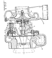
- Fig. 1 shows a turbocharger comprising a central cast bearing housing 12 having a pair of sleeve bearings 14 for supporting a shaft 16 that is attached to a radial inward flow turbine wheel 18.
- the turbine wheel 18 drives the shaft 16 which is in turn connected to a centrifugal compressor 20, contained within a compressor housing 22.
- Rotation of the compressor 20 accelerates air which is discharged into an annular diffuser 24 and then to a scroll-like outlet 26 for converting the velocity head into a static pressure head.
- Pressurized air is directed from the outlet 26, through an appropriate conduit 28, past an aftercooler 30 if desired, and then to an intake manifold 32 of a reciprocating internal combustion engine 34.
- the internal combustion engine utilizes the compressed air to form a combustible mixture which is ignited to drive the engine.
- the products of combustion are fed through an exhaust manifold 36 to an inlet 38 of an inlet volute 44 of a turbine housing 40 which is secured to the bearing housing 12 by a clamp band 42.
- the inlet volute 44 is of gradually decreasing area.
- the volute 44 feeds an annular inlet passage consisting of opposed, radially extending side walls 46 and 48 respectively.
- the wall 46 is integral with the turbine housing 40, but the wall 48 consists of a thin wall ring 52 having an integral, inwardly directed flange 50 and an integral outwardly extending flange 54.
- the flange 54 in annular recess 58 is sandwiched between the turbine housing 40 and a turbine back plate 56 by the clamp band 42.
- a series of vanes 60 are fixed to flange 50 by a suitable method, for example welding, or riveting.
- the vanes 60 are oriented so that they direct incoming gas flow in a tangential direction to provide the appropriate gas flow.
- a variable area control mechanism is incorporated in the turbocharger.
- the mechanism includes an area control element 62 comprising an annular thin wall ring section 64 having an integral, inwardly directed thin wall flange 66 and an integral, outwardly directed flange 68.
- the thickness of the flange 66 does not exceed about six per cent of the outer diameter of the ring shaped array of the vanes 60.
- the junction of the flange 66 with the ring section 64 is rounded at 69 to promote smooth gas flow. It should be noted that the inward diameter of ring 64 is selected so that it is loosely piloted over ring section 52.
- Flange 66 has a plurality of slots 70 which accept the vanes 60 to permit sliding movement of ring section 64 between the side walls 46 and 48.
- Flange 68 has a plurality of holes 72 each of which receives a shaft 74 extending through a hole 76 in theflange 58. As illustrated in figure 2, the hole 72 is a keyhole slot to receive and affix shaft 74 to flange 68.
- the shaft 74 also extends through hole 78, back plate 56, actuator mounting plate 86, and an actuator housing element 82. Housing element 82 is fixed to the actuator mounting plate 86 by screws 88. Plate 86 is in turn connected to back plate 56 by a plurality of fasteners, not shown.
- Shaft 74 connects with an actuator module 80 comprising an annular housing element 84 connected to element 82.
- Shaft 74 has an integral shoulder 90 which provides a stop for an insulating bushing 92.
- Bushing 92 has a boss 94 to pilot a flexible rolling diaphragm 100 sandwiched between a disc 96 and cup 98.
- Another insulating bushing 102 is received over the threaded end 104 of shaft 74, and a nut 106 clamps the diaphragm and associated elements between bushing 102 and flange 90.
- the outer periphery 108 of the rolling diaphragm 100 is clamped between flanges 110 and 112 of housing elements 82 and 84, respectively.
- a spring 116 acts against the interior of housing 84 to push diaphragm 100 and, in turn, shaft 74 towards the right as viewed in Fig. 2.
- the interior of housing element 82 receives an air pressure control signal through an inlet fitting 118.
- fitting 118 can be connected to the inlet manifold 32 of the engine 34 through a conduit 120.
- actuator modules 80 are positioned to the side of the bearing housing 12.
- there are two modules (only one is shown in Fig. 1) secured to pants located 180° from each other around flange 68 to provide the primary support of the area control element 62 and to locate it.
- the turbine wheel 18 is rotated by the passage of exhaust gases from engine exhaust manifold 36. Rotation of turbine wheel 18 causes compressor 20 to rotate and pressurize air for delivery to the intake manifold 32 of the engine 34.
- the spring 116 pushes the area control element 62 towards a position of minimum flow area.
- the ring section 64 is a barrier to flow and flange 66 acts as one wall of the inlet passage so that the gases must flow between it and the opposed wall 46 of the turbine housing. This causes the gas flow to accelerate and achieve a higher entry velocity around the turbine wheel 18.
- the increase in velocity causes an increase in turbine rpm to increase the air pressure in intake manifold 32.
- Conduit 120 senses the pressure in the intake manifold 32 and applies it across the right face of the flexible diaphragm 100 in opposition to the force of the spring 116.
- the air pressure inside housing 82 pushes the flexible diaphragm 100 thereby displacing the area control element 62 to a more open position. This in turn increases the flow area and reduces the velocity of the gases entering the turbine. It can be seen then that the variable area control mechanism varies the velocity entering the turbine to achieve a controlled pressure level at the intake manifold 32.
- control element 62 is relatively thin and can be of stainless steel and can be formed by stamping or pressing it has the following advantages over other control elements:
- the variable area control mechanism of Figs. 1 to 3 is set up to push the flow area control element 62 towards the minimum area position.
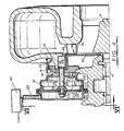
- the mechanism shown in Figs. 4 to 6 pushes the area control element 62 towards the maximum area position.
- a second housing 120 is secured to housing 121 by a clamp band 114.
- the periphery of diaphragm 123 is clamped between housings 120 and 121.
- the movable center portion is sandwiched between plates 125 and 127 which are fixed against a shoulder 131 of an actuating shaft 129 by the insulating bushings 92, 102 and the nut 106.
- Shaft 129 is arranged to abut flange 68 of the area control element 62.
- Housing 120 receives a pressure control signal through an inlet fitting 122 to push diaphragm 123 to the right.
- a plurality of shafts 124 connect to the flange 68 through a slotted connection.
- Shafts 124 extend through openings 126 in the back plate 56, openings 128 in actuator mounting plate 86, and bushings 130.
- On each shaft spring 132 acts against bushing 130 and against a keeper bushing 134, which is slotted at 136 to enable the keeper to be slipped over the groove 138 in shaft 124.
- variable turbine area assembly of Figs. 4 to 6 is biased to the open position illustrated in figure 5 by the springs 132.
- the pressure in housing 120 can be provided by a suitable means, such as a hydraulic, electronic or pneumatic control system 140, which has a predetermined relationship to the intake manifold pressure and housing speed.
- the intake manifold pressure may be used to control a pilot valve which directs pressurized fluid from a control source to the chamber 120.
- the stroke of actuating shaft 129 is sufficient to displace the area control element 62 against turbine housing wall 46 and block flow into the turbine wheel 18.
- the pressure in chamber 120 may be elevated to a high level, in co-operation with termination of fuel to engine 34 so that the area control element 62 blocks flow and acts as a compression brake for engine 34.
- the means for controlling the pressure in chambers 82 or 120 may be direct when intake manifold pressure is used as the pressure control signal or indirect when the control system 140 is used. It should also be apparent that an operating parameter other than intake manifold pressure can be used for the control signal.
Landscapes
- Engineering & Computer Science (AREA)
- Mechanical Engineering (AREA)
- General Engineering & Computer Science (AREA)
- Supercharger (AREA)
- Control Of Turbines (AREA)
Abstract
Description
- This invention relates to a variable inlet area turbine. The turbines concerned can be used in turbochargers.
- Turbochargers are used extensively in modern diesel engines to improve fuel economy and minimize noxious emissions. Such a turbocharger comprises a turbine wheel and housing, a compressor wheel and housing, and a central cast bearing housing between the wheels. The turbine wheel rotates when driven by exhaust gases from an internal combustion engine and causes the compressor wheel to which it is coupled to rotate and compress air, to be supplied to the engine, at a rate that is greater than the rate the engine can naturally aspirate. The turbocharger pressure output is a function of component efficiencies, mass flow through the turbine and compressor and the pressure drop across the turbine.
- One problem that occurs with turbochargers is that acceleration of an engine from a relatively low rpm is accompanied by a noticeable lag in the pressure increase from the turbocharger resulting in a noticeable lag in acceleration. The reason for this is that the inlet area of the turbine 'is designed for maximum rated conditions. As a result, the velocity of the gases passing across the turbine wheel at low engine rpm allow the turbocharger rpm to drop to such a low level that a substantial increase in gas velocity is required to increase the turbocharger rpm.
- In order to overcome this deficiency, a number of schemes have been proposed to provide the turbocharger with a variable inlet area so that at low engine rpm the area may be made small to increase the velocity of the exhaust gases and maintain the turbocharger at a sufficiently high rpm to minimize lag.
- British patent specification no. 1,138,941 describes an example of a variable inlet area arrangement where an annular ring is movable across the turbine inlet to vary the axial dimensions and thus increase or decrease the overall inlet area. The ring has a series of recesses which conform to fixed turbine inlet vanes to permit free movement of the ring. Although it is directed to waterflow, the variable area turbine inlet of British patent specification no. 1,992,733 displays a similar arrangement but includes actuating modules located outside the tubine housing.
- The problem with these prior approaches is that the deposit laden exhaust of an internal combustion engine very quickly fills up the sliding surface between the elements and eventually causes them to stick and impairs their function. For this reason, there have been no practical applications of variable area turbine control of this general type. Furthermore, the complex shapes, such as in British patent specification no. 1,138,941 require expensive manufacturing techniques and involve the use of expensive high temperature alloys which have attendant problems of thermal expansion.
- With a view to overcoming or at least mitigating the above problems there is provided according to the invention a turbine comprising a turbine housing, a radial inward flow turbine wheel mounted for rotation within the housing, said housing having an annular inlet passage defined by two generally radially extending opposed side walls adjacent the periphery of the turbine wheel through which passage a fluid flows for driving the wheel, characterised by means for controlling the flow area of said passage, said control means comprising an axially displaceable ring section and an integral inwardly directed thin wall flange, and means for displacing the ring so as to vary the flow area of the passage.
- The invention will now be further described by way of example, with reference to the accompanying drawings, in which : -
- Fig, 1 is a simplified perspective view of a turbocharger which incorporates a variable inlet area turbine formed according to the invention;
- Fig. 2 is a fragmentary,longitudinal section view on an enlarged scale of the turbocharger illustrated in Fig. 1;
- Fig. 3 is a diagrammatic cross-sectional view on line III-III in Fig. 2;
- Figs. 4 and 5 are fragmentary, longitudinal section views of a turbocharger utilizing another embodiment of turbine formed according to the invention; and
- Fig. 6 is a diagrammatic cross-sectional view on lines VI-VI of Fig. 4.
- Fig. 1 shows a turbocharger comprising a central
cast bearing housing 12 having a pair of sleeve bearings 14 for supporting ashaft 16 that is attached to a radial inwardflow turbine wheel 18. Theturbine wheel 18 drives theshaft 16 which is in turn connected to acentrifugal compressor 20, contained within acompressor housing 22. Rotation of thecompressor 20 accelerates air which is discharged into anannular diffuser 24 and then to a scroll-like outlet 26 for converting the velocity head into a static pressure head. Pressurized air is directed from theoutlet 26, through anappropriate conduit 28, past anaftercooler 30 if desired, and then to anintake manifold 32 of a reciprocatinginternal combustion engine 34. The internal combustion engine utilizes the compressed air to form a combustible mixture which is ignited to drive the engine. The products of combustion are fed through anexhaust manifold 36 to aninlet 38 of aninlet volute 44 of aturbine housing 40 which is secured to the bearinghousing 12 by aclamp band 42. Theinlet volute 44 is of gradually decreasing area. Thevolute 44 feeds an annular inlet passage consisting of opposed, radially extendingside walls wall 46 is integral with theturbine housing 40, but thewall 48 consists of athin wall ring 52 having an integral, inwardly directedflange 50 and an integral outwardly extendingflange 54. Theflange 54 inannular recess 58 is sandwiched between theturbine housing 40 and aturbine back plate 56 by theclamp band 42. A series ofvanes 60 are fixed toflange 50 by a suitable method, for example welding, or riveting. Thevanes 60 are oriented so that they direct incoming gas flow in a tangential direction to provide the appropriate gas flow. - As shown in Fig. 2, a variable area control mechanism is incorporated in the turbocharger. The mechanism includes an
area control element 62 comprising an annular thinwall ring section 64 having an integral, inwardly directedthin wall flange 66 and an integral, outwardly directedflange 68. Preferably the thickness of theflange 66 does not exceed about six per cent of the outer diameter of the ring shaped array of thevanes 60. Preferably, the junction of theflange 66 with thering section 64 is rounded at 69 to promote smooth gas flow. It should be noted that the inward diameter ofring 64 is selected so that it is loosely piloted overring section 52. -
Flange 66 has a plurality of slots 70 which accept thevanes 60 to permit sliding movement ofring section 64 between theside walls Flange 68 has a plurality of holes 72 each of which receives ashaft 74 extending through ahole 76 intheflange 58. As illustrated in figure 2, the hole 72 is a keyhole slot to receive and affixshaft 74 toflange 68. Theshaft 74 also extends throughhole 78,back plate 56,actuator mounting plate 86, and anactuator housing element 82.Housing element 82 is fixed to theactuator mounting plate 86 byscrews 88.Plate 86 is in turn connected toback plate 56 by a plurality of fasteners, not shown. Shaft 74 connects with anactuator module 80 comprising anannular housing element 84 connected toelement 82. Shaft 74 has an integral shoulder 90 which provides a stop for aninsulating bushing 92. Bushing 92 has a boss 94 to pilot aflexible rolling diaphragm 100 sandwiched between adisc 96 andcup 98. Anotherinsulating bushing 102 is received over the threaded end 104 ofshaft 74, and a nut 106 clamps the diaphragm and associated elements betweenbushing 102 and flange 90. Theouter periphery 108 of therolling diaphragm 100 is clamped betweenflanges housing elements spring 116 acts against the interior ofhousing 84 to pushdiaphragm 100 and, in turn,shaft 74 towards the right as viewed in Fig. 2. The interior ofhousing element 82 receives an air pressure control signal through an inlet fitting 118. As illustrated in Fig. 1, fitting 118 can be connected to theinlet manifold 32 of theengine 34 through aconduit 120. - As shown in Fig. 3,
actuator modules 80 are positioned to the side of the bearinghousing 12. Preferably, there are two modules (only one is shown in Fig. 1) secured to pants located 180° from each other aroundflange 68 to provide the primary support of thearea control element 62 and to locate it. - During operation the
turbine wheel 18 is rotated by the passage of exhaust gases fromengine exhaust manifold 36. Rotation ofturbine wheel 18 causescompressor 20 to rotate and pressurize air for delivery to theintake manifold 32 of theengine 34. Thespring 116 pushes thearea control element 62 towards a position of minimum flow area. When theelement 62 is in this position, thering section 64 is a barrier to flow andflange 66 acts as one wall of the inlet passage so that the gases must flow between it and theopposed wall 46 of the turbine housing. This causes the gas flow to accelerate and achieve a higher entry velocity around theturbine wheel 18. The increase in velocity causes an increase in turbine rpm to increase the air pressure inintake manifold 32. Conduit 120 senses the pressure in theintake manifold 32 and applies it across the right face of theflexible diaphragm 100 in opposition to the force of thespring 116. When the manifold pressure starts to exceed a given level selected by the strength of thespring 116, the air pressure insidehousing 82 pushes theflexible diaphragm 100 thereby displacing thearea control element 62 to a more open position. This in turn increases the flow area and reduces the velocity of the gases entering the turbine. It can be seen then that the variable area control mechanism varies the velocity entering the turbine to achieve a controlled pressure level at theintake manifold 32. - Because this
area control element 62 is relatively thin and can be of stainless steel and can be formed by stamping or pressing it has the following advantages over other control elements: - 1. Minimum side edge surface area on which exhaust gas deposits can accumulate so that the element does not tend to seize in any position.
- 2. Ease of manufacture.
- 3. Low cost of manufacture.
- 4. Reduced thermal stresses due not only to the thinness but also to the rounded junction 69 (the junction also improves gas flow around this area control element).
- 5. Low inertia due to its light weight which results in improved responsiveness to changes in intake manifold pressure.
- 6. Lack of restriction of turbine inlet area when this element is in the fully open position (see figure 1).
- 7. Little or no increase in the size of the turbine housing.
- The variable area control mechanism of Figs. 1 to 3 is set up to push the flow
area control element 62 towards the minimum area position. The mechanism shown in Figs. 4 to 6 pushes thearea control element 62 towards the maximum area position. In this latter embodiment, in which parts that are identical to those of Figs. 1 to 3 have identical reference numbers, asecond housing 120 is secured tohousing 121 by aclamp band 114. The periphery ofdiaphragm 123 is clamped betweenhousings plates 125 and 127 which are fixed against a shoulder 131 of an actuating shaft 129 by the insulatingbushings abut flange 68 of thearea control element 62.Housing 120 receives a pressure control signal through an inlet fitting 122 to pushdiaphragm 123 to the right. - As shown, in Figs. 5 and 6, a plurality of
shafts 124 connect to theflange 68 through a slotted connection.Shafts 124 extend throughopenings 126 in theback plate 56,openings 128 inactuator mounting plate 86, andbushings 130. On eachshaft spring 132 acts againstbushing 130 and against akeeper bushing 134, which is slotted at 136 to enable the keeper to be slipped over thegroove 138 inshaft 124. - In operation, the variable turbine area assembly of Figs. 4 to 6 is biased to the open position illustrated in figure 5 by the
springs 132. The pressure inhousing 120 can be provided by a suitable means, such as a hydraulic, electronic orpneumatic control system 140, which has a predetermined relationship to the intake manifold pressure and housing speed. For example, the intake manifold pressure may be used to control a pilot valve which directs pressurized fluid from a control source to thechamber 120. - The stroke of actuating shaft 129 is sufficient to displace the
area control element 62 againstturbine housing wall 46 and block flow into theturbine wheel 18. If desired, the pressure inchamber 120 may be elevated to a high level, in co-operation with termination of fuel toengine 34 so that thearea control element 62 blocks flow and acts as a compression brake forengine 34. - The means for controlling the pressure in
chambers control system 140 is used. It should also be apparent that an operating parameter other than intake manifold pressure can be used for the control signal.
Claims (17)
Applications Claiming Priority (2)
| Application Number | Priority Date | Filing Date | Title |
|---|---|---|---|
| GB8134368 | 1981-11-14 | ||
| GB8134368 | 1981-11-14 |
Publications (2)
| Publication Number | Publication Date |
|---|---|
| EP0080810A1 true EP0080810A1 (en) | 1983-06-08 |
| EP0080810B1 EP0080810B1 (en) | 1988-03-09 |
Family
ID=10525890
Family Applications (1)
| Application Number | Title | Priority Date | Filing Date |
|---|---|---|---|
| EP82305805A Expired EP0080810B1 (en) | 1981-11-14 | 1982-11-02 | A variable inlet area turbine |
Country Status (6)
| Country | Link |
|---|---|
| US (1) | US4499732A (en) |
| EP (1) | EP0080810B1 (en) |
| JP (1) | JPS5891330A (en) |
| BR (1) | BR8206487A (en) |
| DE (1) | DE3278214D1 (en) |
| ES (1) | ES8407336A1 (en) |
Cited By (8)
| Publication number | Priority date | Publication date | Assignee | Title |
|---|---|---|---|---|
| EP0136858A1 (en) * | 1983-09-20 | 1985-04-10 | Holset Engineering Company Limited | Variable area turbine and control system therefor |
| EP0131406A3 (en) * | 1983-07-08 | 1985-05-02 | Holset Engineering Company Limited | A variable inlet area turbine |
| US4679984A (en) * | 1985-12-11 | 1987-07-14 | The Garrett Corporation | Actuation system for variable nozzle turbine |
| DE102009004890A1 (en) * | 2009-01-16 | 2010-07-22 | Bosch Mahle Turbo Systems Gmbh & Co. Kg | Charging device, particularly exhaust gas turbocharger for motor vehicle, has adjusting element, which is adjusted parallel to turbine wheel axis that is operatively connected with rotatably supported guide vane |
| US7810327B2 (en) | 2005-10-20 | 2010-10-12 | Cummins Turbo Technologies Limited | Variable geometry turbine |
| US8601812B2 (en) | 2006-08-04 | 2013-12-10 | Cummins Turbo Technologies Limited | Variable geometry turbine |
| EP2378086A3 (en) * | 2010-04-19 | 2014-04-09 | Hamilton Sundstrand Corporation | Variable turbine nozzle and valve |
| WO2018099618A1 (en) * | 2016-12-01 | 2018-06-07 | Man Diesel & Turbo Se | Turbocharger having sealing surfaces between a nozzle ring and a turbine housing |
Families Citing this family (20)
| Publication number | Priority date | Publication date | Assignee | Title |
|---|---|---|---|---|
| GB8515502D0 (en) * | 1985-06-19 | 1985-07-24 | Holset Engineering Co | Turbine turbocharger |
| US5746058A (en) * | 1996-03-11 | 1998-05-05 | Gits Manufacturing Company | Adjustable actuator for a turbocharger |
| DE19651498C1 (en) * | 1996-12-11 | 1998-04-16 | Daimler Benz Ag | Exhaust turbocharger for IC engine |
| GB9711893D0 (en) * | 1997-06-10 | 1997-08-06 | Holset Engineering Co | Variable geometry turbine |
| DE19819699B4 (en) * | 1998-05-02 | 2005-05-19 | Daimlerchrysler Ag | turbocharger |
| US6109167A (en) * | 1998-06-04 | 2000-08-29 | Gits Manufacturing Company | Actuator with axially movable O-rings between piston and housing |
| US6158956A (en) * | 1998-10-05 | 2000-12-12 | Allied Signal Inc. | Actuating mechanism for sliding vane variable geometry turbine |
| SE9903403L (en) * | 1999-09-22 | 2001-03-23 | Electrolux Ab | Two stroke internal combustion engine |
| DE19956896C1 (en) * | 1999-11-26 | 2001-03-29 | Daimler Chrysler Ag | Exhaust gas turbo charger for IC motor has paddles at radial compressor which can be extended or retracted according to mass flow to improve performance graph and radial compressor operation |
| AU2001221812A1 (en) * | 2000-11-30 | 2002-06-11 | Honeywell Garrett Sa | Variable geometry turbocharger with sliding piston |
| US6652224B2 (en) * | 2002-04-08 | 2003-11-25 | Holset Engineering Company Ltd. | Variable geometry turbine |
| GB0223756D0 (en) * | 2002-10-14 | 2002-11-20 | Holset Engineering Co | Compressor |
| US6968702B2 (en) * | 2003-12-08 | 2005-11-29 | Ingersoll-Rand Energy Systems Corporation | Nozzle bolting arrangement for a turbine |
| US20060130479A1 (en) * | 2004-12-21 | 2006-06-22 | Holm Christopher E | Turbocharger with blow-by gas injection port |
| GB0811228D0 (en) * | 2008-06-19 | 2008-07-30 | Cummins Turbo Tech Ltd | Variable geometric turbine |
| GB2468871B (en) * | 2009-03-25 | 2015-03-18 | Cummins Turbo Tech Ltd | Turbocharger |
| JP5854514B2 (en) * | 2009-08-30 | 2016-02-09 | アーノルド, スティーヴン, ドン.ARNOLD, Steven, Don | Variable swirl turbine |
| DE102010051359A1 (en) * | 2010-11-13 | 2012-05-16 | Daimler Ag | Insert element for a turbine of an exhaust gas turbocharger, exhaust gas turbocharger and turbine for an exhaust gas turbocharger |
| US8979508B2 (en) * | 2012-11-12 | 2015-03-17 | Honeywell International Inc. | Turbocharger and variable-nozzle cartridge therefor |
| KR101568113B1 (en) | 2014-01-28 | 2015-11-20 | 주식회사 인팩 | The actuator of turbo charger |
Citations (9)
| Publication number | Priority date | Publication date | Assignee | Title |
|---|---|---|---|---|
| CH125547A (en) * | 1927-02-21 | 1928-04-16 | Oscar Simmen | Gyroscope. |
| FR667306A (en) * | 1928-02-02 | 1929-10-15 | Rateau Soc | Device for adjusting the operating conditions of centrifugal machines |
| GB874085A (en) * | 1956-11-23 | 1961-08-02 | Garrett Corp | Flow control systems for turbines |
| GB923658A (en) * | 1959-12-30 | 1963-04-18 | Garrett Corp | Improvements relating to variable area nozzle assemblies |
| GB1138941A (en) * | 1965-01-15 | 1969-01-01 | Stuart Swinford Wilson | Improvements in and relating to radial flow turbines |
| US3426964A (en) * | 1966-10-11 | 1969-02-11 | Dresser Ind | Compressor apparatus |
| GB2044860A (en) * | 1979-03-16 | 1980-10-22 | Bbc Brown Boveri & Cie | Turbo-supercharger comprising a device for regulating the absorption capacity of the turbine |
| US4265592A (en) * | 1979-05-09 | 1981-05-05 | Carlini Gerardo P V | Centrifugal fan |
| US4292807A (en) * | 1979-05-02 | 1981-10-06 | United Technologies Corporation | Variable geometry turbosupercharger system for internal combustion engine |
Family Cites Families (7)
| Publication number | Priority date | Publication date | Assignee | Title |
|---|---|---|---|---|
| US1322810A (en) * | 1919-11-25 | Rotary pump with adjustable gate | ||
| GB305214A (en) * | 1928-02-02 | 1929-10-31 | Rateau Soc | Improvements in or relating to means for controlling the running of centrifugal machines |
| US2861774A (en) * | 1950-02-16 | 1958-11-25 | Alfred J Buchi | Inlet control for radial flow turbines |
| US2846185A (en) * | 1955-02-22 | 1958-08-05 | Sfindex | Full admission impulse turbine |
| DE1074206B (en) * | 1958-01-20 | 1960-01-28 | Gebrüder Sulzer Aktiengesellschaft, Winterthur (Schweiz) | Idler wheel for turbo machines |
| DE1428192A1 (en) * | 1962-03-26 | 1969-03-06 | Mannesmann Meer Ag | Radial compressor with changeable flow cross-section |
| JPS5420213A (en) * | 1977-07-18 | 1979-02-15 | Hitachi Ltd | Exhaust gas turbine supercharger |
-
1982
- 1982-11-02 DE DE8282305805T patent/DE3278214D1/en not_active Expired
- 1982-11-02 EP EP82305805A patent/EP0080810B1/en not_active Expired
- 1982-11-09 BR BR8206487A patent/BR8206487A/en unknown
- 1982-11-12 JP JP57197886A patent/JPS5891330A/en active Pending
- 1982-11-12 ES ES517327A patent/ES8407336A1/en not_active Expired
- 1982-11-15 US US06/441,461 patent/US4499732A/en not_active Expired - Lifetime
Patent Citations (9)
| Publication number | Priority date | Publication date | Assignee | Title |
|---|---|---|---|---|
| CH125547A (en) * | 1927-02-21 | 1928-04-16 | Oscar Simmen | Gyroscope. |
| FR667306A (en) * | 1928-02-02 | 1929-10-15 | Rateau Soc | Device for adjusting the operating conditions of centrifugal machines |
| GB874085A (en) * | 1956-11-23 | 1961-08-02 | Garrett Corp | Flow control systems for turbines |
| GB923658A (en) * | 1959-12-30 | 1963-04-18 | Garrett Corp | Improvements relating to variable area nozzle assemblies |
| GB1138941A (en) * | 1965-01-15 | 1969-01-01 | Stuart Swinford Wilson | Improvements in and relating to radial flow turbines |
| US3426964A (en) * | 1966-10-11 | 1969-02-11 | Dresser Ind | Compressor apparatus |
| GB2044860A (en) * | 1979-03-16 | 1980-10-22 | Bbc Brown Boveri & Cie | Turbo-supercharger comprising a device for regulating the absorption capacity of the turbine |
| US4292807A (en) * | 1979-05-02 | 1981-10-06 | United Technologies Corporation | Variable geometry turbosupercharger system for internal combustion engine |
| US4265592A (en) * | 1979-05-09 | 1981-05-05 | Carlini Gerardo P V | Centrifugal fan |
Cited By (8)
| Publication number | Priority date | Publication date | Assignee | Title |
|---|---|---|---|---|
| EP0131406A3 (en) * | 1983-07-08 | 1985-05-02 | Holset Engineering Company Limited | A variable inlet area turbine |
| EP0136858A1 (en) * | 1983-09-20 | 1985-04-10 | Holset Engineering Company Limited | Variable area turbine and control system therefor |
| US4679984A (en) * | 1985-12-11 | 1987-07-14 | The Garrett Corporation | Actuation system for variable nozzle turbine |
| US7810327B2 (en) | 2005-10-20 | 2010-10-12 | Cummins Turbo Technologies Limited | Variable geometry turbine |
| US8601812B2 (en) | 2006-08-04 | 2013-12-10 | Cummins Turbo Technologies Limited | Variable geometry turbine |
| DE102009004890A1 (en) * | 2009-01-16 | 2010-07-22 | Bosch Mahle Turbo Systems Gmbh & Co. Kg | Charging device, particularly exhaust gas turbocharger for motor vehicle, has adjusting element, which is adjusted parallel to turbine wheel axis that is operatively connected with rotatably supported guide vane |
| EP2378086A3 (en) * | 2010-04-19 | 2014-04-09 | Hamilton Sundstrand Corporation | Variable turbine nozzle and valve |
| WO2018099618A1 (en) * | 2016-12-01 | 2018-06-07 | Man Diesel & Turbo Se | Turbocharger having sealing surfaces between a nozzle ring and a turbine housing |
Also Published As
| Publication number | Publication date |
|---|---|
| BR8206487A (en) | 1983-09-27 |
| US4499732A (en) | 1985-02-19 |
| DE3278214D1 (en) | 1988-04-14 |
| ES517327A0 (en) | 1983-12-16 |
| JPS5891330A (en) | 1983-05-31 |
| ES8407336A1 (en) | 1983-12-16 |
| EP0080810B1 (en) | 1988-03-09 |
Similar Documents
| Publication | Publication Date | Title |
|---|---|---|
| US4499732A (en) | Turbocharger having a variable inlet area turbine | |
| US4557665A (en) | Variable inlet area turbine | |
| EP0131406B1 (en) | A variable inlet area turbine | |
| KR100669487B1 (en) | Variable shape turbocharger | |
| US8328535B2 (en) | Diffuser restraint system and method | |
| EP0127398B1 (en) | Compressors and turbochargers | |
| EP2143909B1 (en) | Vane ring assembly with stepped spacer for a turbocharger with variable turbine geometry | |
| US4657476A (en) | Variable area turbine | |
| US4490622A (en) | Turbocharger and adaptations thereof | |
| US8590305B2 (en) | Simplified variable geometry turbocharger with variable nozzle | |
| EP0227638B1 (en) | Improvements in or relating to gas turbine power plant | |
| EP1120546A2 (en) | Variable-capacity turbine | |
| US5868553A (en) | Exhaust gas turbine of an exhaust gas turbocharger | |
| US3975911A (en) | Turbocharger | |
| EP0248624B1 (en) | Variable capacity turbine | |
| EP2431575B1 (en) | Variable geometry turbine | |
| GB2474344A (en) | Variable geometry turbine inlet | |
| KR20040044142A (en) | Variable geometry turbine | |
| US5498128A (en) | Radial-flow exhaust gas turbocharger turbine with adjustable guide vanes | |
| KR20160061442A (en) | Variable turbine geometry vane with single-axle, self-centering pivot feature | |
| EP0030230A1 (en) | TURBOCHARGER USED IN AN INTERNAL COMBUSTION ENGINE OR TURBOREACTOR. | |
| US6938404B2 (en) | Supercharged open cycle gas turbine engine | |
| WO2011042694A2 (en) | Variable geometry turbine | |
| GB2525240A (en) | Variable geometry turbine | |
| JPS6137791Y2 (en) |
Legal Events
| Date | Code | Title | Description |
|---|---|---|---|
| PUAI | Public reference made under article 153(3) epc to a published international application that has entered the european phase |
Free format text: ORIGINAL CODE: 0009012 |
|
| AK | Designated contracting states |
Designated state(s): DE FR GB IT SE |
|
| 17P | Request for examination filed |
Effective date: 19830708 |
|
| GRAA | (expected) grant |
Free format text: ORIGINAL CODE: 0009210 |
|
| AK | Designated contracting states |
Kind code of ref document: B1 Designated state(s): DE FR GB IT SE |
|
| ITF | It: translation for a ep patent filed | ||
| REF | Corresponds to: |
Ref document number: 3278214 Country of ref document: DE Date of ref document: 19880414 |
|
| ET | Fr: translation filed | ||
| PLBE | No opposition filed within time limit |
Free format text: ORIGINAL CODE: 0009261 |
|
| STAA | Information on the status of an ep patent application or granted ep patent |
Free format text: STATUS: NO OPPOSITION FILED WITHIN TIME LIMIT |
|
| 26N | No opposition filed | ||
| ITTA | It: last paid annual fee | ||
| EAL | Se: european patent in force in sweden |
Ref document number: 82305805.2 |
|
| PGFP | Annual fee paid to national office [announced via postgrant information from national office to epo] |
Ref country code: SE Payment date: 19981105 Year of fee payment: 17 |
|
| PG25 | Lapsed in a contracting state [announced via postgrant information from national office to epo] |
Ref country code: SE Free format text: LAPSE BECAUSE OF NON-PAYMENT OF DUE FEES Effective date: 19991103 |
|
| EUG | Se: european patent has lapsed |
Ref document number: 82305805.2 |
|
| PGFP | Annual fee paid to national office [announced via postgrant information from national office to epo] |
Ref country code: GB Payment date: 20011031 Year of fee payment: 20 |
|
| PGFP | Annual fee paid to national office [announced via postgrant information from national office to epo] |
Ref country code: FR Payment date: 20011113 Year of fee payment: 20 |
|
| PGFP | Annual fee paid to national office [announced via postgrant information from national office to epo] |
Ref country code: DE Payment date: 20011119 Year of fee payment: 20 |
|
| REG | Reference to a national code |
Ref country code: GB Ref legal event code: IF02 |
|
| PG25 | Lapsed in a contracting state [announced via postgrant information from national office to epo] |
Ref country code: GB Free format text: LAPSE BECAUSE OF EXPIRATION OF PROTECTION Effective date: 20021101 |
|
| REG | Reference to a national code |
Ref country code: GB Ref legal event code: PE20 Effective date: 20021101 |