EP0080444B1 - Refractory lining for a furnace - Google Patents
Refractory lining for a furnace Download PDFInfo
- Publication number
- EP0080444B1 EP0080444B1 EP82850219A EP82850219A EP0080444B1 EP 0080444 B1 EP0080444 B1 EP 0080444B1 EP 82850219 A EP82850219 A EP 82850219A EP 82850219 A EP82850219 A EP 82850219A EP 0080444 B1 EP0080444 B1 EP 0080444B1
- Authority
- EP
- European Patent Office
- Prior art keywords
- lining
- anchoring
- elements
- anchoring elements
- furnace
- Prior art date
- Legal status (The legal status is an assumption and is not a legal conclusion. Google has not performed a legal analysis and makes no representation as to the accuracy of the status listed.)
- Expired
Links
Images

Classifications
-
- F—MECHANICAL ENGINEERING; LIGHTING; HEATING; WEAPONS; BLASTING
- F27—FURNACES; KILNS; OVENS; RETORTS
- F27D—DETAILS OR ACCESSORIES OF FURNACES, KILNS, OVENS, OR RETORTS, IN SO FAR AS THEY ARE OF KINDS OCCURRING IN MORE THAN ONE KIND OF FURNACE
- F27D1/00—Casings; Linings; Walls; Roofs
- F27D1/14—Supports for linings
- F27D1/141—Anchors therefor
-
- F—MECHANICAL ENGINEERING; LIGHTING; HEATING; WEAPONS; BLASTING
- F27—FURNACES; KILNS; OVENS; RETORTS
- F27B—FURNACES, KILNS, OVENS, OR RETORTS IN GENERAL; OPEN SINTERING OR LIKE APPARATUS
- F27B7/00—Rotary-drum furnaces, i.e. horizontal or slightly inclined
- F27B7/14—Rotary-drum furnaces, i.e. horizontal or slightly inclined with means for agitating or moving the charge
- F27B7/16—Rotary-drum furnaces, i.e. horizontal or slightly inclined with means for agitating or moving the charge the means being fixed relatively to the drum, e.g. composite means
- F27B7/161—Rotary-drum furnaces, i.e. horizontal or slightly inclined with means for agitating or moving the charge the means being fixed relatively to the drum, e.g. composite means the means comprising projections jutting out from the wall
- F27B7/162—Rotary-drum furnaces, i.e. horizontal or slightly inclined with means for agitating or moving the charge the means being fixed relatively to the drum, e.g. composite means the means comprising projections jutting out from the wall the projections consisting of separate lifting elements, e.g. lifting shovels
-
- F—MECHANICAL ENGINEERING; LIGHTING; HEATING; WEAPONS; BLASTING
- F27—FURNACES; KILNS; OVENS; RETORTS
- F27B—FURNACES, KILNS, OVENS, OR RETORTS IN GENERAL; OPEN SINTERING OR LIKE APPARATUS
- F27B7/00—Rotary-drum furnaces, i.e. horizontal or slightly inclined
- F27B7/20—Details, accessories, or equipment peculiar to rotary-drum furnaces
- F27B7/28—Arrangements of linings
Definitions
- the invention relates to a lining of a furnace, for example a cement rotary furnace with coolers and by-pass channels or walls in a walking beam furnace.
- Refractory linings in furnaces are often made by casting with a refractory casting mass.
- the walls of the furnace consist of steel sheet which is a natural outer casting mould.
- Anchoring irons of heat-resistant flat steel bars are welded into the steel sheet and the purpose of said bars is to keep the refractory lining in its position.
- the lining according to the invention is designed in such a manner that future removal in connection with relining will be facilitated. It is characterized thereby that the anchoring irons are cast into pre-fabricated conical, pyramid or wedge-shaped ceramical elements, preferably having a cross-section increasing in direction from the furnace wall.
- the anchoring elements are attached to the wall of the furnace by a through-going bolt and a nut or are keyed onto sheet forks welded into the walls of the furnace.
- a refractory ceramic casting mass is cast between the anchoring elements to a thickness in level with the tops of the anchoring elements to form a coherent monolithic lining.
- the anchoring elements as well as the intermediate casting are made from a refractory casting mass, for example according to US Patent No. 3,982,953, the disclosure of which is incorporated herein by reference.
- the inner mould wait is suitably made out of thermoplastic boards which in mounting are heated and glued to the top sides of the prefabricated anchoring elements.
- the anchoring elements may have different heights if the lining shall have varying thickness.
- the refractory lining In the cooling section of a cement rotary furnace the refractory lining often has protruding axial walls or cams functioning as lifter bars for the hot cement clinker for improving heat transfer.
- a lining of this type is called lifter bar lining.
- the anchoring elements are designed in a particular manner so as to function also as lifter bar elements.
- the lifter bars are subjected to high stresses. Therefore, they are made of high-refractory wear resistant ceramic material, e.g. according to US Patent No. 4,244,745, the disclosure of which is incorporated herein by reference, and they are provided with two or several strong bolts for anchoring to the mantle wall.
- the elements have a width corresponding to the desired width of the cam and a length which is 1 to 3 times the width.
- the cam elements have preferably essentially the shape of a parallelepiped, the lower part of the surfaces constituting parts of the longitudinal sides of the cam, however, inclining inwardly.
- the lower part of the cam elements thereby obtain wedge shape contributing to keeping in position the ceramic casting mass applied between the cams.
- the elements are instead attached to sheet forks welded to the wall.
- the clearing is started by chipping a ditch in the lining adjacent to the sheet wall. Then the lining is chipped away in the adjacent area of the lining in a direction towards the ditch and in direction to the open side of the sheet forks holding the element.
- a tubular cement rotary furnace 1 is connected to eight satellite coolers 4 through openings 2 and angular elements or so- ' called cones 3.
- coolers 4 consist of a cylindric sheet mantle 5 with an interior ceramic lining.
- the lining consists of two types of anchoring elements, namely wholly surroundingly cast anchoring elements 6 and cam elements 7 and an intermediary refractory ceramic casting mass 8. Elements 6 are at the same level as the intermediary cast 8.
- Cam elements 7 extend over the surface of elements 6 and 8.
- a plurality of elements 7 are arranged adjacent to each other in a row and form a cam extending along the length of cooler 4.
- the juxtaposed side surfaces are thus plane and parallel to each other.
- the two other juxtaposed side surfaces of the cam elements have upper planar surfaces which are parallel to each other and lower planar surfaces inclining downwardly inwardly.
- the conical anchoring element 6 is provided with an attachment device consisting of a flat steel bar 9 which is welded to a bolt 10.
- the bolt 10 thus extends through a hole 11 drilled in the mantle sheet 5 of the cooler and is attached with a nut.
- Cam element 7 is provided with two or several similar fastening devices of flat steel 12 welded to bolts 13. Also said bolts are inserted into holes drilled in the mantle sheet and are drawn with nuts.
- a conical anchoring element 14 is provided with another type of fastening device.
- a flat steel bar 15 is cast into anchoring element 14 and is exposed in a cavity 16 and designed therein as a clamp 17.
- the clamp In mounting the clamp is inserted into a steel fork 19 welded to mantle sheet 18. By hitting a mandrel engaging clamp 17 the anchoring element 14 is wedged up into the fork.
- anchoring elements 6, 7 and 14 with accompanying fastening devices are first made by casting a refractory ceramic casting mass.
- the blocks are allowed to dry and are then attached to a sheet mantle in the desired number of anchoring elements, whereafter a refractory ceramic casting mass 8 is applied between the anchoring elements.
- Casting mass 8 is then allowed to dry. Burning of the casting mass 8 and the anchoring elements 6, 7 and 14 takes place when heating up the furnace. In this manner a coherent monolithic lining is formed, the removal of which is greatly facilitated by the arrangement of the invention.
Landscapes
- Engineering & Computer Science (AREA)
- Mechanical Engineering (AREA)
- General Engineering & Computer Science (AREA)
- Furnace Housings, Linings, Walls, And Ceilings (AREA)
- Glass Compositions (AREA)
- Laminated Bodies (AREA)
- Lining Or Joining Of Plastics Or The Like (AREA)
- Details Of Garments (AREA)
Abstract
Description
- The invention relates to a lining of a furnace, for example a cement rotary furnace with coolers and by-pass channels or walls in a walking beam furnace.
- Refractory linings in furnaces are often made by casting with a refractory casting mass. The walls of the furnace consist of steel sheet which is a natural outer casting mould. Anchoring irons of heat-resistant flat steel bars are welded into the steel sheet and the purpose of said bars is to keep the refractory lining in its position.
- The quality of casting masses and anchoring irons have been progressively improved so as to increase their working life. At the same time, however, the difficulty in removing the old lining for relining purposes has increased.
- The lining according to the invention is designed in such a manner that future removal in connection with relining will be facilitated. It is characterized thereby that the anchoring irons are cast into pre-fabricated conical, pyramid or wedge-shaped ceramical elements, preferably having a cross-section increasing in direction from the furnace wall. The anchoring elements are attached to the wall of the furnace by a through-going bolt and a nut or are keyed onto sheet forks welded into the walls of the furnace.
- A refractory ceramic casting mass is cast between the anchoring elements to a thickness in level with the tops of the anchoring elements to form a coherent monolithic lining. The anchoring elements as well as the intermediate casting are made from a refractory casting mass, for example according to US Patent No. 3,982,953, the disclosure of which is incorporated herein by reference.
- In rotary furnaces having a cylindrical mantle no inner mould wall is usually required. The casting can take place against the surface which temporarily constitutes bottom of the furnace and can progressively proceed through step-wise rotation. For casting against vertical or strongly inclined surfaces an inner mould wall will, however, be required.
- If the surfaces have a pronounced curvature the inner mould wait is suitably made out of thermoplastic boards which in mounting are heated and glued to the top sides of the prefabricated anchoring elements. The anchoring elements may have different heights if the lining shall have varying thickness.
- In the cooling section of a cement rotary furnace the refractory lining often has protruding axial walls or cams functioning as lifter bars for the hot cement clinker for improving heat transfer. A lining of this type is called lifter bar lining. In these sections the anchoring elements are designed in a particular manner so as to function also as lifter bar elements. The lifter bars are subjected to high stresses. Therefore, they are made of high-refractory wear resistant ceramic material, e.g. according to US Patent No. 4,244,745, the disclosure of which is incorporated herein by reference, and they are provided with two or several strong bolts for anchoring to the mantle wall. The elements have a width corresponding to the desired width of the cam and a length which is 1 to 3 times the width. The cam elements have preferably essentially the shape of a parallelepiped, the lower part of the surfaces constituting parts of the longitudinal sides of the cam, however, inclining inwardly. The lower part of the cam elements thereby obtain wedge shape contributing to keeping in position the ceramic casting mass applied between the cams.
- When removing the lining the nuts on the bolts extending through the walls of the furnace are loosened. By powerful impacts on the bolts from the exterior side of the furnace the lining is ruptured at the interarea between the pre- fabricated anchoring elements and the part of the lining cast in situ. Thereby the anchoring irons fall out and also a greater part of the remaining part of the lining no longer anchored follows along. Only a relatively minor postcleaning work with a chipper will be required.
- In certain parts of the furnace where the back of the wall of the furnace is not accessible or where for other reasons through-bolts cannot be used the elements are instead attached to sheet forks welded to the wall. In this case the clearing is started by chipping a ditch in the lining adjacent to the sheet wall. Then the lining is chipped away in the adjacent area of the lining in a direction towards the ditch and in direction to the open side of the sheet forks holding the element.
-
- Fig. 1 shows, partly in section, the discharge end of a cement rotary furnace;
- Fig. 2 shows on a larger scale a part of section 11-11 of the cooler of Fig. 1;
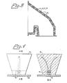
- Fig. 3 shows on a larger scale a detail of Fig. 1;
- Fig. 4 shows in two side views an embodiment with fork attachment.
- According to Fig. 1 a tubular cement rotary furnace 1 is connected to eight
satellite coolers 4 throughopenings 2 and angular elements or so- ' called cones 3. - As is clear from Fig. 2
coolers 4 consist of acylindric sheet mantle 5 with an interior ceramic lining. The lining consists of two types of anchoring elements, namely wholly surroundingly castanchoring elements 6 and cam elements 7 and an intermediary refractoryceramic casting mass 8.Elements 6 are at the same level as theintermediary cast 8. Cam elements 7 extend over the surface ofelements cooler 4. The juxtaposed side surfaces are thus plane and parallel to each other. The two other juxtaposed side surfaces of the cam elements have upper planar surfaces which are parallel to each other and lower planar surfaces inclining downwardly inwardly. - The
conical anchoring element 6 is provided with an attachment device consisting of aflat steel bar 9 which is welded to abolt 10. Thebolt 10 thus extends through ahole 11 drilled in themantle sheet 5 of the cooler and is attached with a nut. - Cam element 7 is provided with two or several similar fastening devices of
flat steel 12 welded tobolts 13. Also said bolts are inserted into holes drilled in the mantle sheet and are drawn with nuts. - A
conical anchoring element 14 is provided with another type of fastening device. Aflat steel bar 15 is cast into anchoringelement 14 and is exposed in acavity 16 and designed therein as aclamp 17. In mounting the clamp is inserted into asteel fork 19 welded tomantle sheet 18. By hitting amandrel engaging clamp 17 theanchoring element 14 is wedged up into the fork. - When manufacturing a lining according to the
drawing anchoring elements ceramic casting mass 8 is applied between the anchoring elements. Castingmass 8 is then allowed to dry. Burning of thecasting mass 8 and theanchoring elements
Claims (5)
Priority Applications (1)
| Application Number | Priority Date | Filing Date | Title |
|---|---|---|---|
| AT82850219T ATE16728T1 (en) | 1981-11-19 | 1982-11-02 | REFRACTORY LINING OF A FURNACE. |
Applications Claiming Priority (2)
| Application Number | Priority Date | Filing Date | Title |
|---|---|---|---|
| SE8106899A SE8106899L (en) | 1981-11-19 | 1981-11-19 | ELDFAST FOOD FOR OVEN |
| SE8106899 | 1981-11-19 |
Publications (4)
| Publication Number | Publication Date |
|---|---|
| EP0080444A2 EP0080444A2 (en) | 1983-06-01 |
| EP0080444A3 EP0080444A3 (en) | 1983-08-03 |
| EP0080444B1 true EP0080444B1 (en) | 1985-11-27 |
| EP0080444B2 EP0080444B2 (en) | 1990-04-18 |
Family
ID=20345076
Family Applications (1)
| Application Number | Title | Priority Date | Filing Date |
|---|---|---|---|
| EP82850219A Expired - Lifetime EP0080444B2 (en) | 1981-11-19 | 1982-11-02 | Refractory lining for a furnace |
Country Status (8)
| Country | Link |
|---|---|
| US (1) | US4569659A (en) |
| EP (1) | EP0080444B2 (en) |
| AT (1) | ATE16728T1 (en) |
| DE (1) | DE3267713D1 (en) |
| DK (1) | DK152310C (en) |
| ES (1) | ES8308995A1 (en) |
| MX (1) | MX158939A (en) |
| SE (1) | SE8106899L (en) |
Families Citing this family (20)
| Publication number | Priority date | Publication date | Assignee | Title |
|---|---|---|---|---|
| US4763584A (en) * | 1987-03-02 | 1988-08-16 | Combustion Engineering, Inc. | Means of attaching refractory to a furnace wall |
| DE8711747U1 (en) * | 1987-08-29 | 1987-10-22 | Juenger & Graeter Gmbh & Co Feuerfestbau, 6830 Schwetzingen, De | |
| WO1989012789A1 (en) * | 1988-06-13 | 1989-12-28 | Siemens Aktiengesellschaft | Heat shield arrangement with low coolant fluid requirement |
| US4975049A (en) * | 1989-06-14 | 1990-12-04 | General Refractories Company | Refractory block for rotary kiln |
| US4960058A (en) * | 1989-10-26 | 1990-10-02 | Merkle Engineers, Inc. | Self-positioning refractory structure |
| US5033863A (en) * | 1990-02-06 | 1991-07-23 | Cedarapids, Inc. | Method and arrangement of a flight attachment |
| US5040973A (en) * | 1990-05-04 | 1991-08-20 | Rollins Environmental Services (Tx) Inc. | Rotary reactor and lifter assembly |
| US5299933A (en) * | 1991-12-24 | 1994-04-05 | Quigley Company, Inc. | Rotary kiln with a polygonal lining |
| US5277580A (en) * | 1993-02-16 | 1994-01-11 | Lea-Con, Inc. | Wall construction system for refractory furnaces |
| DE4343319A1 (en) * | 1993-12-18 | 1995-06-22 | Abb Patent Gmbh | Combustion chamber with a ceramic lining |
| FR2725505B1 (en) * | 1994-10-11 | 1996-11-08 | Pa Technologies | ROTARY OVEN HAVING LIFTERS AND METHOD FOR REPAIRING SUCH OVENS |
| US5862641A (en) * | 1996-01-06 | 1999-01-26 | Lea-Con, Inc. | Kiln anchor |
| US5695329A (en) * | 1996-09-24 | 1997-12-09 | Orcutt; Jeffrey W. | Rotary kiln construction with improved insulation means |
| JP2942254B2 (en) * | 1997-10-27 | 1999-08-30 | タキ産業株式会社 | Ceramic fiber block for high temperature furnace lining |
| DE59810637D1 (en) | 1998-11-30 | 2004-02-26 | Alstom Switzerland Ltd | Ceramic lining for a combustion chamber |
| US6569327B2 (en) * | 2001-01-23 | 2003-05-27 | Rg Delaware, Inc. | Apparatus for directing fluids through a filter system |
| US6705859B2 (en) * | 2002-03-01 | 2004-03-16 | Andritz Inc. | Tapered grizzly bars for lime kiln |
| US6688884B2 (en) | 2002-06-06 | 2004-02-10 | Harbison-Walker Refractories Company | Rotary kiln heat exchanger and method of assembling same |
| DE102004036109B4 (en) * | 2004-07-08 | 2006-08-03 | BLüCHER GMBH | Rotary tube for activated carbon production and its use |
| US9279245B2 (en) * | 2013-07-09 | 2016-03-08 | Silicon Refractory Anchoring Systems B.V. | Anchoring assembly, anchoring nut for use in an anchoring assembly and the use of an anchoring assembly for anchoring a liner of a cured lining material |
Family Cites Families (19)
| Publication number | Priority date | Publication date | Assignee | Title |
|---|---|---|---|---|
| GB422025A (en) * | 1933-03-24 | 1935-01-03 | Gaston Francisque Saintenoy | Wall with plastic refractory lining cooled by air circulation and method of construction for the same |
| US2021610A (en) * | 1934-06-14 | 1935-11-19 | Quint George | Refractory anchor |
| DE914831C (en) * | 1952-02-15 | 1954-12-13 | Didier Werke Ag | Lining of rotary tube furnaces |
| US3211387A (en) * | 1962-09-17 | 1965-10-12 | Koppers Co Inc | Grinding mill lining and control of the wear thereof |
| DE1254803B (en) * | 1964-10-02 | 1967-11-23 | Detrick M H Co | Firebox wall with anchor stones |
| BR6573585D0 (en) * | 1965-09-29 | 1973-03-08 | Magnesita Sa | NEW AND ORIGINAL CLOSING SYSTEM IN MOLDED REFRACTORY MATERIAL FOR RINGS AND SIMILAR ARCHES |
| US3563521A (en) * | 1969-02-26 | 1971-02-16 | California Portland Cement Co | Materials lifter construction and installation in kilns |
| DE1922679C3 (en) * | 1969-05-03 | 1979-05-10 | Plibrico Co Gmbh, 4000 Duesseldorf | Fireproof ceiling or wall construction for lining industrial furnaces or the like. and method of installation |
| US3592454A (en) * | 1969-08-07 | 1971-07-13 | California Portland Cement Co | Formless installation of materials lifters and kiln lining |
| AT320701B (en) * | 1970-05-22 | 1975-02-25 | Dl Plibrico Company G M B H | Fireproof ceiling or wall construction for lining industrial furnaces or the like. and assembly process for this |
| US3836612A (en) * | 1971-02-18 | 1974-09-17 | Kaiser Aluminium Chem Corp | Method for lining rotary kilns |
| SE380251B (en) * | 1973-11-26 | 1975-11-03 | Hoeganaes Ab | Refractory mass usable for casting, framing or stamping of furnace linings and for the manufacture of bottling or casting tubes for molten metals |
| DK21475A (en) * | 1975-01-23 | 1976-07-24 | Dansk Leca As | ROTARY OVEN FOR THE MANUFACTURE OF A DISPLAYED CLAY PRODUCT AND PROCEDURE FOR THE MANUFACTURE OF THE ROTARY OVEN |
| JPS525605A (en) * | 1975-07-03 | 1977-01-17 | Shinagawa Refract Co Ltd | Inner lining construction of rotary furnaces |
| DE2541447A1 (en) * | 1975-09-17 | 1977-03-31 | Fleischmann Adolf A Fa | Preformed refractory tiles for furnace roofs and walls - secured to furnace casing by anchors |
| DE2557846A1 (en) * | 1975-12-22 | 1977-06-30 | Hilti Ag | FASTENING ELEMENT FOR FIRE-RESISTANT LINING |
| US4136965A (en) * | 1978-03-31 | 1979-01-30 | Bethlehem Steel Corporation | Mixer block for use in rotary drums |
| SE417950B (en) * | 1978-06-22 | 1981-04-27 | Hoeganaes Ab | ELDFAST MOLDING MASS FOR PREPARING MONOLITIC FEEDS AND WAY TO PREPARE |
| SU903675A1 (en) * | 1980-06-06 | 1982-02-07 | Государственный Всесоюзный Научно-Исследовательский Институт Цементной Промышленности | Rotary furnace heat exchange apparatus |
-
1981
- 1981-11-19 SE SE8106899A patent/SE8106899L/en not_active Application Discontinuation
-
1982
- 1982-11-02 AT AT82850219T patent/ATE16728T1/en not_active IP Right Cessation
- 1982-11-02 EP EP82850219A patent/EP0080444B2/en not_active Expired - Lifetime
- 1982-11-02 DE DE8282850219T patent/DE3267713D1/en not_active Expired
- 1982-11-04 US US06/439,122 patent/US4569659A/en not_active Expired - Lifetime
- 1982-11-18 MX MX195248A patent/MX158939A/en unknown
- 1982-11-18 ES ES517456A patent/ES8308995A1/en not_active Expired
- 1982-11-18 DK DK514782A patent/DK152310C/en not_active IP Right Cessation
Also Published As
| Publication number | Publication date |
|---|---|
| EP0080444A3 (en) | 1983-08-03 |
| ES517456A0 (en) | 1983-10-01 |
| DK514782A (en) | 1983-05-20 |
| DE3267713D1 (en) | 1986-01-09 |
| DK152310B (en) | 1988-02-15 |
| DK152310C (en) | 1988-07-11 |
| EP0080444A2 (en) | 1983-06-01 |
| EP0080444B2 (en) | 1990-04-18 |
| ATE16728T1 (en) | 1985-12-15 |
| MX158939A (en) | 1989-03-31 |
| ES8308995A1 (en) | 1983-10-01 |
| US4569659A (en) | 1986-02-11 |
| SE8106899L (en) | 1983-05-20 |
Similar Documents
| Publication | Publication Date | Title |
|---|---|---|
| EP0080444B1 (en) | Refractory lining for a furnace | |
| AU2007218923B2 (en) | A rotary kiln | |
| US4911681A (en) | Ceramic conveyor belt connector rod end fixation | |
| EP3048369B1 (en) | Metal-ceramic compound grate bar for a waste-incinerator grate | |
| US4131265A (en) | Slag pots | |
| US5423294A (en) | Furnace tile and expansion joint | |
| US4846677A (en) | Castable buttress for rotary kiln heat exchanger and method of fabricating | |
| CA2308420C (en) | Pipe refractory insulation for furnaces | |
| US4275258A (en) | Water-cooled box designed as wall element for a melting furnace | |
| JP2000179825A (en) | Fire grate rod exhibiting high temperature stability | |
| CN104813128B (en) | Arch brick, cylindrical internal lining of a rotary kiln and rotary kiln | |
| CA1223725A (en) | Multiple hearth furnace chamber | |
| EP0061263A1 (en) | Anchoring refractory materials to a refractory lining | |
| EP0028523A1 (en) | Insulated skidrail | |
| DE4430265B4 (en) | Distribution chute for installation in an oven | |
| US2573195A (en) | Prefabricated flue construction | |
| US4545763A (en) | Inlet for a cooler in a rotary furnace | |
| GB2233079A (en) | Refractory lining of furnaces | |
| US2475102A (en) | Refractory lining for furnace doors | |
| US5078595A (en) | Carbon flue wall and method of making | |
| CN220288203U (en) | Rotary kiln lining prefabricated block | |
| KR200250013Y1 (en) | Precast block for immersion pipe in vacuum degassing facility | |
| US20220018600A1 (en) | Structural matrix for stave | |
| RU2251648C1 (en) | Furnace arch | |
| CA2135667C (en) | Shaft furnace |
Legal Events
| Date | Code | Title | Description |
|---|---|---|---|
| PUAI | Public reference made under article 153(3) epc to a published international application that has entered the european phase |
Free format text: ORIGINAL CODE: 0009012 |
|
| PUAL | Search report despatched |
Free format text: ORIGINAL CODE: 0009013 |
|
| AK | Designated contracting states |
Designated state(s): AT CH DE FR GB IT LI NL SE |
|
| AK | Designated contracting states |
Designated state(s): AT CH DE FR GB IT LI NL SE |
|
| 17P | Request for examination filed |
Effective date: 19831118 |
|
| ITF | It: translation for a ep patent filed |
Owner name: BARZANO' E ZANARDO MILANO S.P.A. |
|
| GRAA | (expected) grant |
Free format text: ORIGINAL CODE: 0009210 |
|
| AK | Designated contracting states |
Designated state(s): AT CH DE FR GB IT LI NL SE |
|
| REF | Corresponds to: |
Ref document number: 16728 Country of ref document: AT Date of ref document: 19851215 Kind code of ref document: T |
|
| ET | Fr: translation filed | ||
| REF | Corresponds to: |
Ref document number: 3267713 Country of ref document: DE Date of ref document: 19860109 |
|
| PLBI | Opposition filed |
Free format text: ORIGINAL CODE: 0009260 |
|
| 26 | Opposition filed |
Opponent name: A. FLEISCHMANN GMBH Effective date: 19860217 |
|
| NLR1 | Nl: opposition has been filed with the epo |
Opponent name: A. FLEISCHMANN GMBH |
|
| PLAB | Opposition data, opponent's data or that of the opponent's representative modified |
Free format text: ORIGINAL CODE: 0009299OPPO |
|
| R26 | Opposition filed (corrected) |
Opponent name: A. FLEISCHMANN GMBH Effective date: 19860217 |
|
| ITF | It: translation for a ep patent filed |
Owner name: BARZANO' E ZANARDO MILANO S.P.A. |
|
| PUAH | Patent maintained in amended form |
Free format text: ORIGINAL CODE: 0009272 |
|
| STAA | Information on the status of an ep patent application or granted ep patent |
Free format text: STATUS: PATENT MAINTAINED AS AMENDED |
|
| 27A | Patent maintained in amended form |
Effective date: 19900418 |
|
| AK | Designated contracting states |
Kind code of ref document: B2 Designated state(s): AT CH DE FR GB IT LI NL SE |
|
| ET3 | Fr: translation filed ** decision concerning opposition | ||
| NLR2 | Nl: decision of opposition | ||
| NLR3 | Nl: receipt of modified translations in the netherlands language after an opposition procedure | ||
| ITTA | It: last paid annual fee | ||
| PGFP | Annual fee paid to national office [announced via postgrant information from national office to epo] |
Ref country code: SE Payment date: 19921117 Year of fee payment: 11 Ref country code: FR Payment date: 19921117 Year of fee payment: 11 |
|
| PGFP | Annual fee paid to national office [announced via postgrant information from national office to epo] |
Ref country code: NL Payment date: 19921130 Year of fee payment: 11 |
|
| PG25 | Lapsed in a contracting state [announced via postgrant information from national office to epo] |
Ref country code: SE Effective date: 19931103 |
|
| PG25 | Lapsed in a contracting state [announced via postgrant information from national office to epo] |
Ref country code: NL Effective date: 19940601 |
|
| NLV4 | Nl: lapsed or anulled due to non-payment of the annual fee | ||
| PG25 | Lapsed in a contracting state [announced via postgrant information from national office to epo] |
Ref country code: FR Effective date: 19940729 |
|
| REG | Reference to a national code |
Ref country code: FR Ref legal event code: ST |
|
| EUG | Se: european patent has lapsed |
Ref document number: 82850219.5 Effective date: 19940610 |
|
| PGFP | Annual fee paid to national office [announced via postgrant information from national office to epo] |
Ref country code: GB Payment date: 19961011 Year of fee payment: 15 |
|
| PGFP | Annual fee paid to national office [announced via postgrant information from national office to epo] |
Ref country code: DE Payment date: 19961107 Year of fee payment: 15 |
|
| PGFP | Annual fee paid to national office [announced via postgrant information from national office to epo] |
Ref country code: AT Payment date: 19961108 Year of fee payment: 15 |
|
| PGFP | Annual fee paid to national office [announced via postgrant information from national office to epo] |
Ref country code: CH Payment date: 19961111 Year of fee payment: 15 |
|
| REG | Reference to a national code |
Ref country code: CH Ref legal event code: PUE Owner name: HOEGANAES AB TRANSFER- SVENSKA HOEGANAES AB |
|
| REG | Reference to a national code |
Ref country code: GB Ref legal event code: 732E |
|
| PG25 | Lapsed in a contracting state [announced via postgrant information from national office to epo] |
Ref country code: GB Free format text: LAPSE BECAUSE OF NON-PAYMENT OF DUE FEES Effective date: 19971102 Ref country code: AT Free format text: LAPSE BECAUSE OF NON-PAYMENT OF DUE FEES Effective date: 19971102 |
|
| PG25 | Lapsed in a contracting state [announced via postgrant information from national office to epo] |
Ref country code: LI Free format text: LAPSE BECAUSE OF NON-PAYMENT OF DUE FEES Effective date: 19971130 Ref country code: CH Free format text: LAPSE BECAUSE OF NON-PAYMENT OF DUE FEES Effective date: 19971130 |
|
| GBPC | Gb: european patent ceased through non-payment of renewal fee |
Effective date: 19971102 |
|
| REG | Reference to a national code |
Ref country code: CH Ref legal event code: PL |
|
| PG25 | Lapsed in a contracting state [announced via postgrant information from national office to epo] |
Ref country code: DE Free format text: LAPSE BECAUSE OF NON-PAYMENT OF DUE FEES Effective date: 19980801 |