EP0080390B1 - Structure nouvelle de caisses-enregistreuses multiples, notamment pour supermarchés - Google Patents
Structure nouvelle de caisses-enregistreuses multiples, notamment pour supermarchés Download PDFInfo
- Publication number
- EP0080390B1 EP0080390B1 EP19820401935 EP82401935A EP0080390B1 EP 0080390 B1 EP0080390 B1 EP 0080390B1 EP 19820401935 EP19820401935 EP 19820401935 EP 82401935 A EP82401935 A EP 82401935A EP 0080390 B1 EP0080390 B1 EP 0080390B1
- Authority
- EP
- European Patent Office
- Prior art keywords
- posts
- checkout
- structure according
- checkout counters
- secured
- Prior art date
- Legal status (The legal status is an assumption and is not a legal conclusion. Google has not performed a legal analysis and makes no representation as to the accuracy of the status listed.)
- Expired
Links
- 238000010438 heat treatment Methods 0.000 claims description 5
- 230000005611 electricity Effects 0.000 claims 2
- 230000003019 stabilising effect Effects 0.000 claims 2
- 238000004873 anchoring Methods 0.000 claims 1
- 230000000712 assembly Effects 0.000 claims 1
- 238000000429 assembly Methods 0.000 claims 1
- 238000009434 installation Methods 0.000 description 6
- 230000006641 stabilisation Effects 0.000 description 5
- 238000011105 stabilization Methods 0.000 description 5
- 229910000746 Structural steel Inorganic materials 0.000 description 2
- 229910052751 metal Inorganic materials 0.000 description 2
- 238000009423 ventilation Methods 0.000 description 2
- 241000282341 Mustela putorius furo Species 0.000 description 1
- 238000004378 air conditioning Methods 0.000 description 1
- 230000000295 complement effect Effects 0.000 description 1
- 238000002513 implantation Methods 0.000 description 1
- 239000002184 metal Substances 0.000 description 1
- 229910052754 neon Inorganic materials 0.000 description 1
- GKAOGPIIYCISHV-UHFFFAOYSA-N neon atom Chemical compound [Ne] GKAOGPIIYCISHV-UHFFFAOYSA-N 0.000 description 1
- 230000000717 retained effect Effects 0.000 description 1
- 230000011664 signaling Effects 0.000 description 1
- 238000003466 welding Methods 0.000 description 1
Images

Classifications
-
- A—HUMAN NECESSITIES
- A47—FURNITURE; DOMESTIC ARTICLES OR APPLIANCES; COFFEE MILLS; SPICE MILLS; SUCTION CLEANERS IN GENERAL
- A47F—SPECIAL FURNITURE, FITTINGS, OR ACCESSORIES FOR SHOPS, STOREHOUSES, BARS, RESTAURANTS OR THE LIKE; PAYING COUNTERS
- A47F9/00—Shop, bar, bank or like counters
- A47F9/02—Paying counters
- A47F9/04—Check-out counters, e.g. for self-service stores
Definitions
- the present invention relates to a new structure of multiple cash registers, in particular for supermarkets.
- the invention aims to provide a structure which avoids these multiple and complex interventions.
- a structure of multiple cash registers of the type used at the outlet of large-scale stores, and consisting of an integral assembly essentially composed of a tray for receiving products, a corridor of circulation of said products and of fixing brackets for the cash register, characterized in that it comprises on the one hand stabilization plates embedded in the ground, at least two in number per cash register, and on the other hand posts, in the same number, which can fit onto said plates 2, joined at their upper part by a beam per box having practically the same length as this, while the posts of two neighboring boxes are also joined at their upper part by a cross member whose length corresponds to the spacing of two boxes, said sets for cash registers each being fixed in overhang on the two associated posts.
- the floor can be executed without any other subsequent intervention, providing only the embedding of the stabilization plates.
- the assembly team successively sets up, and in this order, the posts, the side members, the sleepers and finally the boxes. In this way, perfect stabilization of the entire structure is obtained as soon as the necessary has been done for two neighboring boxes. It is then possible to mount, from this first structure, the other neighboring boxes, and this in a successive and modular manner.
- the framework constituted by the posts, the side members and the cross-members carries, fixed to it in the direction of the length and between two neighboring boxes, a lighting box.
- this frame can carry, fixed on it in the transverse direction between two neighboring boxes, a section of ventilation-heating duct whose length corresponds to the spacing of two boxes and whose ends have means of connection to d 'other sections.
- the frame can also carry, fixed on it, in the transverse direction, between two neighboring boxes, a section of electric power cable support whose length corresponds to the spacing of two boxes, while one can simultaneously provide preferably that each support section carries sections of power supply cables of the same length and provided with bridging means with other sections, while each post also carries a section of cable provided with bridging means and descending up to at the associated cash register.
- the frame can also carry, fixed on it between two neighboring boxes, a section of false ceiling and / or vertical closing strips.
- the location of the structure is provided in a rectangular mesh network, extending over the width of a store, so as to allow the establishment of a series of cash registers, the number of which can vary from two to around twenty , the vertices of this rectangular network bearing the reference 1.
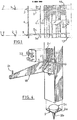
- the floor is of a perfectly uniform conventional embodiment, with the exception of the installation, in each of the vertices 1 of the network, of stabilization plates 2, preferably metallic, which include a horizontal stabilization plate 2a, a lower anchor rod 2b fixed under the plate and a section of tube 2c fixed above this plate.
- stabilization plates 2 preferably metallic, which include a horizontal stabilization plate 2a, a lower anchor rod 2b fixed under the plate and a section of tube 2c fixed above this plate.
- the assembly structure proper comprises a framework essentially constituted by posts 3, beams 4 and crosspieces 5.
- the posts 3 are of square section which can fit exactly at their base on the tube sections 2c of the plates.
- the distance between these posts, that is to say between the vertices 1 of the mesh of FIG. 1 is significantly smaller than the overall longitudinal dimension of a conventional cash register 6.
- the latter has been shown schematically in a very simplified manner, but it is quite clear that it includes all the desired arrangements such as the tray for receiving the products, the circulation corridor for the latter, the consoles for fixing the body. itself and all the accessories you want.
- the posts 3 each carry, fixed by factory welding, a section of metal profile in C7 extending vertically beyond the post.
- Fig. 1 schematically represents the successive positioning of the elements of the structure, and these will be described in ferret as the assembly order.
- a spar 4 is then fixed which is itself constituted by a hollow tube whose length corresponds approximately to that of the body 6, and which has end plates 8.
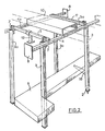
- the framework is completed by two crosspieces 5 which are also constituted by hollow sections, the length of which corresponds very exactly to the spacing between the posts 3 and 3a, that is to say to the dimension of the mesh in the transverse direction.
- These crosspieces are fixed on the profile sections 7, for example above the side members 4 and 4a.
- the profiles 7 consist of metal elements having perforations and the side members 4 and 4a and the crosspieces 5 are fixed using hooks which penetrate into these perforations.
- the rear crossmember 5a located on the side of the body outlet, carries, welded and retained on its upper face, a support for an electric power cable 9, of U-section, the length of which also corresponds to the spacing between posts.
- This support 9 receives sections of electric cable having the same length, and having at their ends means of connection or bridging.
- the side members 4 and 4a carry, fixed on their upper face during assembly, a section of room duct 10, that is to say used for heating and / or ventilation, the length of this sheath section still corresponding to the transverse distance between posts (the latter corresponds to the pitch between the cash registers 6 themselves).
- the sheath sections are, as shown in FIG. 1 on the right, fixed after the installation of the successive beams. These sheath sections have particularly sealed connection means at their ends, ensuring the continuity of the sheath over the entire width of the magazine. On their lower face, these sheath sections have air vents, not shown, from which extend sleeves which open at the level of the false ceilings which will be described later.
- the structure thus far described therefore comprises the framework formed of posts, beams and crosspieces, and additional elements 9 and 10 which are situated above the upper plane which constitute the beams and crosspieces.
- a lighting box 11 of parallelepiped shape and whose length corresponds practically to that of the box 6 and which is oriented parallel to the side rails 4a and disposed at equal distance therebetween, being suspended on the crosspieces 5 and 5a by two bent bars 12 which are fixed on its upper face and hang on said crosspieces.
- the box 11 contains in particular lighting elements such as neon tubes 13, while on the rear side of this box, on the side of the outlet of the box, and outside the size of this same box, is fixed a block 14 of signaling presenting information on the number of the box and its closing possible.
- Such a light box is mounted, as shown in FIG. 1, after the sections of ambient sheath 10 have been fixed to the side members.
- each box 11 has, on its lower longitudinal edges, angles 15. Between the angles 15 facing two neighboring boxes 11, there is mounted a false ceiling 16 which can be either of the perforated type, in the form of braces or parallel slats, either full to improve soundproofing. Due to the small span existing between two boxes, such a false ceiling is self-supporting. There are further provided vertical strips 17 which are fixed between two neighboring boxes 11, at the front and rear faces of the latter, so as to ensure continuity of the facade of this structure shown in FIG. 3. The false ceilings and the strips are, of course, mounted as the assembly progresses along the successive boxes, their fixing being possible as soon as two boxes 11 have been put in place.
- each cash register 6 is mounted on two posts 3, using brackets 18, directed transversely with respect to the posts.
- Each console is for example constituted by an L-shaped angle iron, a wing of which is fixed to the post by screwing on a counter-plate 19 which is placed inside the hollow post, the fixing being done by screws through a vertical light 20 formed in the post, while the other wing of the angle iron, which extends perpendicular to the post, receives on its upper edge the cash register 6, with immobilization by means of pins 21.
- each post 3 are housed several cable sections 22 which extend to its upper end, having bridging means which allow them to be connected with the cable sections contained in the cable support 9, while at their lower end, these cables 22 pass through a plate 23 which is attached to the post so as to mask a rectangular opening 24 into which the slot 20 opens, this opening 24 more easily allowing the positioning of the inner counterplate 19 for fixing the console.
- These cables for example three in number, are respectively connected to the various electrical devices, for example to the cash register, the intercom and the computer unit.
- consoles 18 can have various shapes, depending on the particular structure of the cash register 6, and for example have two or three wings for supporting the lateral elements of the cash register. It should be noted that the mounting of the angles by screws and lights allows the height adjustment at will of the level of the body.
- the framework produced allows the attachment of other ancillary elements, for example a surveillance mirror which can be disposed between the two posts 3 and 3a located on the outlet side.
- ancillary elements for example a surveillance mirror which can be disposed between the two posts 3 and 3a located on the outlet side.
- the height of the posts, and therefore the level at which the side members 4 and the cross members 5 are fixed, is provided so that, once the light boxes and false ceilings are fixed below this level, the circulation customers can easily be done between the boxes.
- the assembly considered is very advantageous since once two boxes have been mounted, a rigid frame is obtained which serves as a basis for extending the entire structure to any number of boxes. It suffices, moreover, as shown in FIG. 1, to set up new posts, then crosspieces which come to be placed exactly in alignment with the previous crosspieces, as well as new sections of ambient duct also coming to be connected to the previous sections. More particularly, the alignment of the rear crosspieces 5a allows easy connection by bridging of the various sections of cable contained in the cable supports 9, as well as bridging also with the sections of cable contained in the posts 3, which ensures the realization an electrical distribution in an extremely simple way, without requiring the presence of specialized electricians. It is clear that all the elements of the structure are prepared in the workshop and that only the plates 2 had to be embedded in the floor before assembly.
Landscapes
- Floor Finish (AREA)
- Freezers Or Refrigerated Showcases (AREA)
Applications Claiming Priority (2)
| Application Number | Priority Date | Filing Date | Title |
|---|---|---|---|
| FR8119889 | 1981-10-22 | ||
| FR8119889A FR2515397A1 (fr) | 1981-10-22 | 1981-10-22 | Structure nouvelle de caisses-enregistreuses multiples, notamment pour supermarches |
Publications (2)
| Publication Number | Publication Date |
|---|---|
| EP0080390A1 EP0080390A1 (fr) | 1983-06-01 |
| EP0080390B1 true EP0080390B1 (fr) | 1986-03-05 |
Family
ID=9263303
Family Applications (1)
| Application Number | Title | Priority Date | Filing Date |
|---|---|---|---|
| EP19820401935 Expired EP0080390B1 (fr) | 1981-10-22 | 1982-10-21 | Structure nouvelle de caisses-enregistreuses multiples, notamment pour supermarchés |
Country Status (4)
| Country | Link |
|---|---|
| EP (1) | EP0080390B1 (enExample) |
| DE (1) | DE3269676D1 (enExample) |
| ES (1) | ES8307399A1 (enExample) |
| FR (1) | FR2515397A1 (enExample) |
Families Citing this family (1)
| Publication number | Priority date | Publication date | Assignee | Title |
|---|---|---|---|---|
| GB0520735D0 (en) * | 2005-10-13 | 2005-11-23 | Specialist Joinery Fittings Lt | A modular furniture system |
Family Cites Families (3)
| Publication number | Priority date | Publication date | Assignee | Title |
|---|---|---|---|---|
| US3534933A (en) * | 1968-07-02 | 1970-10-20 | Mervin J Zimmerman | Change dispenser stand |
| US3829187A (en) * | 1972-03-23 | 1974-08-13 | H Stewart | Counter fixture |
| FR2419237A1 (fr) * | 1978-03-10 | 1979-10-05 | Alser Sa | Dispositif transporteur pour l'encaissement de produits a la sortie du magasin |
-
1981
- 1981-10-22 FR FR8119889A patent/FR2515397A1/fr active Granted
-
1982
- 1982-10-21 ES ES516713A patent/ES8307399A1/es not_active Expired
- 1982-10-21 DE DE8282401935T patent/DE3269676D1/de not_active Expired
- 1982-10-21 EP EP19820401935 patent/EP0080390B1/fr not_active Expired
Also Published As
| Publication number | Publication date |
|---|---|
| ES516713A0 (es) | 1983-07-01 |
| ES8307399A1 (es) | 1983-07-01 |
| EP0080390A1 (fr) | 1983-06-01 |
| FR2515397A1 (fr) | 1983-04-29 |
| FR2515397B1 (enExample) | 1984-01-06 |
| DE3269676D1 (en) | 1986-04-10 |
Similar Documents
| Publication | Publication Date | Title |
|---|---|---|
| CA2181938C (fr) | Element porteur pour structures en treillis | |
| EP0642754A1 (fr) | Paroi de fond de présentoir et présentoir intégrant ladite paroi | |
| EP0338872B1 (fr) | Dispositif de présentation de marchandises et produits divers, notamment dans des magasins de vente | |
| EP2779334A1 (fr) | Enveloppe électrique à agencement mécanique amélioré | |
| EP0080390B1 (fr) | Structure nouvelle de caisses-enregistreuses multiples, notamment pour supermarchés | |
| EP0351279B1 (fr) | Procédé pour l'installation, sur un support, d'au moins un appareillage électrique. | |
| EP0940515B1 (fr) | Elément modulaire pour la constitution d'un plafond et plafond constitué par un assemblage de tels éléments modulaires | |
| FR2595878A1 (fr) | Coffret de logement d'appareillages electriques | |
| EP0589115B1 (fr) | Plafond | |
| EP0926282A1 (fr) | Mécanique d'armure du type Jacquard et métier à tisser équipé d'une telle mécanique | |
| FR2522050A1 (fr) | Ossature de stand d'exposition | |
| EP0798953B1 (fr) | Armoire électrique extensible, et à socle intégré | |
| WO2011055037A2 (fr) | Appareil et systeme d'exposition de produits | |
| EP2453540B1 (fr) | Rail de support universel | |
| FR2638345A1 (fr) | Dispositif de rangement et de presentation, notamment pour magasins de detail | |
| FR2757360A1 (fr) | Dispositif modulaire d'agencement, notamment du type gondole | |
| FR2683240A1 (fr) | Cabine d'insonorisation. | |
| FR2483989A1 (fr) | Plancher technique et dispositif de fixation d'une baie electrique a un tel plancher | |
| FR2664633A1 (fr) | Plafond suspendu. | |
| EP1629744B1 (fr) | Panneau de fond pour mobilier métallique de rayonnages | |
| EP3319188A1 (fr) | Système d'assemblage d'armoires électriques d'un tableau électrique | |
| FR2637642A1 (fr) | Dispositif pour le positionnement de cloisons et, notamment, de cloisons de stands pour exposition temporaire | |
| FR2776004A1 (fr) | Panneau de coffrage pour la realisation des ouvrages en beton et son dispositif de liaison rapide pour la fixation d'accessoires | |
| BE895938A (fr) | Meubles constitues d'elements separes, juxtaposables | |
| FR2586441A1 (fr) | Procede pour realiser un faux plafond, et panneaux pour sa mise en oeuvre |
Legal Events
| Date | Code | Title | Description |
|---|---|---|---|
| PUAI | Public reference made under article 153(3) epc to a published international application that has entered the european phase |
Free format text: ORIGINAL CODE: 0009012 |
|
| AK | Designated contracting states |
Designated state(s): BE DE GB IT |
|
| 17P | Request for examination filed |
Effective date: 19830711 |
|
| ITF | It: translation for a ep patent filed | ||
| GRAA | (expected) grant |
Free format text: ORIGINAL CODE: 0009210 |
|
| AK | Designated contracting states |
Kind code of ref document: B1 Designated state(s): BE DE GB IT |
|
| REF | Corresponds to: |
Ref document number: 3269676 Country of ref document: DE Date of ref document: 19860410 |
|
| PLBE | No opposition filed within time limit |
Free format text: ORIGINAL CODE: 0009261 |
|
| STAA | Information on the status of an ep patent application or granted ep patent |
Free format text: STATUS: NO OPPOSITION FILED WITHIN TIME LIMIT |
|
| 26N | No opposition filed | ||
| PGFP | Annual fee paid to national office [announced via postgrant information from national office to epo] |
Ref country code: BE Payment date: 19890929 Year of fee payment: 8 |
|
| PGFP | Annual fee paid to national office [announced via postgrant information from national office to epo] |
Ref country code: GB Payment date: 19890930 Year of fee payment: 8 |
|
| ITTA | It: last paid annual fee | ||
| PG25 | Lapsed in a contracting state [announced via postgrant information from national office to epo] |
Ref country code: GB Effective date: 19901021 |
|
| PG25 | Lapsed in a contracting state [announced via postgrant information from national office to epo] |
Ref country code: BE Effective date: 19901031 |
|
| PGFP | Annual fee paid to national office [announced via postgrant information from national office to epo] |
Ref country code: DE Payment date: 19901221 Year of fee payment: 9 |
|
| BERE | Be: lapsed |
Owner name: S.A. ALSER Effective date: 19901031 |
|
| GBPC | Gb: european patent ceased through non-payment of renewal fee | ||
| PG25 | Lapsed in a contracting state [announced via postgrant information from national office to epo] |
Ref country code: DE Effective date: 19920701 |