EP0080376B1 - Method and apparatus for diagnosing a servomotor control circuit - Google Patents
Method and apparatus for diagnosing a servomotor control circuit Download PDFInfo
- Publication number
- EP0080376B1 EP0080376B1 EP82306251A EP82306251A EP0080376B1 EP 0080376 B1 EP0080376 B1 EP 0080376B1 EP 82306251 A EP82306251 A EP 82306251A EP 82306251 A EP82306251 A EP 82306251A EP 0080376 B1 EP0080376 B1 EP 0080376B1
- Authority
- EP
- European Patent Office
- Prior art keywords
- servomotor
- control unit
- pulse
- pulse distributor
- circuit
- Prior art date
- Legal status (The legal status is an assumption and is not a legal conclusion. Google has not performed a legal analysis and makes no representation as to the accuracy of the status listed.)
- Expired
Links
- 238000000034 method Methods 0.000 title claims description 30
- 230000000694 effects Effects 0.000 claims description 8
- 230000004044 response Effects 0.000 claims description 4
- 230000002401 inhibitory effect Effects 0.000 claims 2
- 230000007257 malfunction Effects 0.000 description 11
- 230000008901 benefit Effects 0.000 description 3
- 238000003754 machining Methods 0.000 description 3
- 230000008569 process Effects 0.000 description 3
- 238000002405 diagnostic procedure Methods 0.000 description 2
- 238000010586 diagram Methods 0.000 description 2
- 230000010354 integration Effects 0.000 description 2
- 230000007246 mechanism Effects 0.000 description 2
- 230000002411 adverse Effects 0.000 description 1
- 230000000994 depressogenic effect Effects 0.000 description 1
- 238000005516 engineering process Methods 0.000 description 1
- 230000006870 function Effects 0.000 description 1
- 230000004048 modification Effects 0.000 description 1
- 238000012986 modification Methods 0.000 description 1
- 230000002441 reversible effect Effects 0.000 description 1
Images
Classifications
-
- G—PHYSICS
- G05—CONTROLLING; REGULATING
- G05B—CONTROL OR REGULATING SYSTEMS IN GENERAL; FUNCTIONAL ELEMENTS OF SUCH SYSTEMS; MONITORING OR TESTING ARRANGEMENTS FOR SUCH SYSTEMS OR ELEMENTS
- G05B19/00—Programme-control systems
- G05B19/02—Programme-control systems electric
- G05B19/18—Numerical control [NC], i.e. automatically operating machines, in particular machine tools, e.g. in a manufacturing environment, so as to execute positioning, movement or co-ordinated operations by means of programme data in numerical form
- G05B19/19—Numerical control [NC], i.e. automatically operating machines, in particular machine tools, e.g. in a manufacturing environment, so as to execute positioning, movement or co-ordinated operations by means of programme data in numerical form characterised by positioning or contouring control systems, e.g. to control position from one programmed point to another or to control movement along a programmed continuous path
- G05B19/21—Numerical control [NC], i.e. automatically operating machines, in particular machine tools, e.g. in a manufacturing environment, so as to execute positioning, movement or co-ordinated operations by means of programme data in numerical form characterised by positioning or contouring control systems, e.g. to control position from one programmed point to another or to control movement along a programmed continuous path using an incremental digital measuring device
- G05B19/23—Numerical control [NC], i.e. automatically operating machines, in particular machine tools, e.g. in a manufacturing environment, so as to execute positioning, movement or co-ordinated operations by means of programme data in numerical form characterised by positioning or contouring control systems, e.g. to control position from one programmed point to another or to control movement along a programmed continuous path using an incremental digital measuring device for point-to-point control
- G05B19/231—Numerical control [NC], i.e. automatically operating machines, in particular machine tools, e.g. in a manufacturing environment, so as to execute positioning, movement or co-ordinated operations by means of programme data in numerical form characterised by positioning or contouring control systems, e.g. to control position from one programmed point to another or to control movement along a programmed continuous path using an incremental digital measuring device for point-to-point control the positional error is used to control continuously the servomotor according to its magnitude
-
- G—PHYSICS
- G05—CONTROLLING; REGULATING
- G05B—CONTROL OR REGULATING SYSTEMS IN GENERAL; FUNCTIONAL ELEMENTS OF SUCH SYSTEMS; MONITORING OR TESTING ARRANGEMENTS FOR SUCH SYSTEMS OR ELEMENTS
- G05B19/00—Programme-control systems
- G05B19/02—Programme-control systems electric
- G05B19/18—Numerical control [NC], i.e. automatically operating machines, in particular machine tools, e.g. in a manufacturing environment, so as to execute positioning, movement or co-ordinated operations by means of programme data in numerical form
- G05B19/406—Numerical control [NC], i.e. automatically operating machines, in particular machine tools, e.g. in a manufacturing environment, so as to execute positioning, movement or co-ordinated operations by means of programme data in numerical form characterised by monitoring or safety
- G05B19/4062—Monitoring servoloop, e.g. overload of servomotor, loss of feedback or reference
-
- G—PHYSICS
- G05—CONTROLLING; REGULATING
- G05B—CONTROL OR REGULATING SYSTEMS IN GENERAL; FUNCTIONAL ELEMENTS OF SUCH SYSTEMS; MONITORING OR TESTING ARRANGEMENTS FOR SUCH SYSTEMS OR ELEMENTS
- G05B2219/00—Program-control systems
- G05B2219/30—Nc systems
- G05B2219/34—Director, elements to supervisory
- G05B2219/34448—Integrated servo control circuit fixed to housing, remote from cpu
-
- G—PHYSICS
- G05—CONTROLLING; REGULATING
- G05B—CONTROL OR REGULATING SYSTEMS IN GENERAL; FUNCTIONAL ELEMENTS OF SUCH SYSTEMS; MONITORING OR TESTING ARRANGEMENTS FOR SUCH SYSTEMS OR ELEMENTS
- G05B2219/00—Program-control systems
- G05B2219/30—Nc systems
- G05B2219/34—Director, elements to supervisory
- G05B2219/34466—Bad circuits, watchdog, alarm, indication
-
- G—PHYSICS
- G05—CONTROLLING; REGULATING
- G05B—CONTROL OR REGULATING SYSTEMS IN GENERAL; FUNCTIONAL ELEMENTS OF SUCH SYSTEMS; MONITORING OR TESTING ARRANGEMENTS FOR SUCH SYSTEMS OR ELEMENTS
- G05B2219/00—Program-control systems
- G05B2219/30—Nc systems
- G05B2219/36—Nc in input of data, input key till input tape
- G05B2219/36551—Inhibiting control after detecting data error
-
- G—PHYSICS
- G05—CONTROLLING; REGULATING
- G05B—CONTROL OR REGULATING SYSTEMS IN GENERAL; FUNCTIONAL ELEMENTS OF SUCH SYSTEMS; MONITORING OR TESTING ARRANGEMENTS FOR SUCH SYSTEMS OR ELEMENTS
- G05B2219/00—Program-control systems
- G05B2219/30—Nc systems
- G05B2219/37—Measurements
- G05B2219/37541—Switch off measuring, control system during test of encoder, resolver
Definitions
- the present invention relates to a method and apparatus for diagnosing a circuit for controlling a servomotor to check the circuit for malfunctions, and more particularly but not exclusively to a method of and apparatus for diagnosing a servomotor control circuit for malfunctioning of an LSI (Large-Scale Integration) circuit which constitutes a digital circuit in the servomotor control circuit.
- LSI Large-Scale Integration
- the numerical control system has, in addition to a numerical control unit, a positional control circuit which mainly comprises a pulse distributor for carrying out arithmetic operations for pulse distribution based on positional or path data, a position detector such as a pulse coder for generating a positional pulse each time the servomotor rotates through a predetermined anglu- lar interval, an error register for computing and storing the difference (hereinafter referred to as an "error") between the number of distributed pulses produced by the pulse distributor and the number of positional pulses, a digital-to-analog converter (hereinafter referred to as a "D/A converter”) for converting the error into an analog quantity, and a speed control circuit for driving the servomotor in response to an output from the D/A converter.
- a positional control circuit which mainly comprises a pulse distributor for carrying out arithmetic operations for pulse distribution based on positional or path data, a position detector such as a pulse coder for generating a positional pulse each time the
- the positional control circuit thus serves to drive the servomotor in response to the output from the D/A converter to position a tool or table in a commanded location or move the tool or table along.a commanded path for performing desired machining on a workpiece mounted on the table.
- a numerical control system is disclosed in DE-A-2 649 115.
- the recent rapid progress of the technology of integrating logic circuits has reached the point where a great number of circuits can be incorporated on a single LSI chip.
- This advantage has allowed the pulse distribuor, the error register, a portion of the D/A converter, and the digital control unit to be assembled as one LSI circuit, such that the posiitonal control circuit can be composed of a reduced number of circuit parts, smaller in size, and less costly to construct.
- the LSI circuit is also advantageous in that the circuit components assembled thereon are more reliable in operation.
- LSI circuits sometimes suffer from various failures such as a power supply fault, no clock pulse supplied, and continues application of a clear signal.
- the LSI circuit tends to be adversely affected to a large extent as it has a complex circuit arrangement due to an increased rate of integration.
- the LSI circuit causes a workpiece to be machined in error, with the results that the workpiece which is expensive will be spoiled, the rate of machining the workpiece will be reduced, and mechanical parts of the machine tool will be damaged.
- a method of diagnosing a servomotor control circuit including a pulse distributor for carrying out arithmetic operations for pulse distribution based on motion data commanded by a control unit, a position detector for generating a positional pulse each time a servomotor rotates through a predetermined angular interval, an error storage unit for computing and storing the difference between the number of positional pulses generated by the position detector and the number of distributed pulses generated by the pulse distibutor, and a D/A converter for converting the difference into an analog output, whereby the servomotor can be controlled by the analog output from the D/A converter, said method being characterised by:
- an apparatus for diagnosing a servomotor control circuit including a pulse distributor for carrying out arithmetic operations for pulse distribution based on motion data commanded by a control unit, a position detector for generating a positional pulse each time a servomotor rotates through a predetermined angular interval, an error storage unit for computing and storing the difference between the number of positional pulses generated by the position detector and the number of distributed pulses generated by the pulse distributor, and a D/A converter for converting the difference into an analog output, whereby the servomotor can be controlled by the analog output from the D/A converter, the apparatus being adapted and arranged to execute, when in use, a diagnosing method characterised by:
- Examples of the present invention may provide a method and apparatus for diagnosing a servomotor control circuit for malfunctions thereof.
- Examples of the present invention may provide a method and apparatus for diagnosing a servomotor control circuit for malfunctions thereof with a control unit for supplying commands to the servomotor control circuit.
- Examples of the present invention may provide a method and apparatus for diagnosing a servomotor control circuit assembled as an LSI circuit for malfunctions thereof.
- Examples of the present invention may provide a method and apparatus for diagnosing a servomotor control circuit for malfunctions thereof without any special diagnostic unit.
- Examples of the present invnetion may provide a method and apparatus for diagnosing a servomotor control circuit for malfunctions of a digital circuit section thereof.
- a method and apparatus for diagnosing a servomotor position control circuit including a pulse distributor for carrying out arithmetic operations for pulse distribution based on command data given by a control unit, a position detector for generating a positional pulse each time a servomotor rotates through a predetermined angular interval, an error storage unit for computing and storing the difference between the number of positional pulses generated by the position detector and the number of distributed pulses generated by the pulse distributor and a D/A converter for converting the difference into an analog output, whereby the servomotor can be controlled by the analog output from the D/A converter.
- the method comprises the steps of supplying a numerical value from the control unit to the pulse distributor to enable the latter to effect the arithmetic operations while the servomotor is de-energized, reading a stored content of the error storage unit supplied with the distributed pulses from the pulse distributor into the control unit, and checking the servomotor control circuit for normal and malfunctioning conditions by comparing the stored content as read by the control unit with the numerical value.
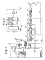
- a numerical control unit 11 is composed of a microcomputer comprising a read only memory (ROM) 11 a for storing a control program, a random access memory (RAM) 11b for storing processed data and various parameters, and a processor 11c for processing numerical control data based on the control program stored in the ROM 11a a and an NC program punched in a paper tape (described later), the ROM 11a, the RAM 11b, and the processor 11c being interconnected by a bus line BUS.
- the NC program punched in the paper tape 12 is read by a tape reader 13.
- Digital input and output data transmitted between a machine tool and the numerical control unit 11 is controlled by a power sequence circuit 14.
- An LSI circuit 15 incorporates an integrated digital circuit section of a positional control circuit.
- the LSI circuit 15 comprises a pulse distributor 15a for effecting arithmetic operations for pulse disbribution based on motion data given by the numerical control unit 11 to produce distributed pulses Pc, an error register 15b in the form of a reversible counter for computing and storing the difference (error) Er between the number of positional pulses FP generated each time a servomotor rotates through a predetermined angular interval, a register 15c for storing a gain setting supplied from the processor 11 c, a multiplier 15d for multiplying the content of the error register 15b with the gain setting stored in the register 15c, an analog switch 15e, and other digital circuits (not shown).
- the pulse distributor 15a and the register 15c are connected to the bus line BUS through input/output ports (not shown).
- An analog adder 16 produces a voltage proportional to the error Er.
- the analog switch 15e and the analog adder 16 jointly constitute a digital-to-analog (D/A) converter.
- the analog adder 16 includes a plurality of resistors R1, R2, R4, ... having resistances 2° . r, 2 1 - r, 2 2 .
- an operational amplifier DAP for the analog switch 15e includes a decoder DEC for decoding an output from the multiplier 15d and a plurality of transistor switches S1 through Si which can be turned on and off by an output from the decoder DEC.
- the analog adder 16 produces a voltage proportional to the output from the multiplier 15.
- Designated by the reference numeral 17 is a known speed control circuit comprising of differential amplifier for producing an output proportional to the difference between a speed of rotation of the servomotor as detected by a non-illustrated detector and an output from the analog adder 16, and an amplifier for amplifying an output from the differential amplifier.
- the servomotor which is denoted by the reference numeral 18, is operatively coupled to a pulse coder 19 for generating a positional pulse each time the servomotor rotates through a predetermined angular interval.
- the positional control system shown in Fig. 1 serves to control the position of a movable part of the machine tool only along a single axis such as an X axis.
- the processor 11c When NC data read out of the tape 12 is positional or path data, the processor 11c computes incremental values AX, AY, AZ along the three-dimensional axes, respectively, according to a numerical control program in the control program stored in the memory 11a, and delivers the computed values to the pulse distributor 15a. Since only the X-axis positional control system is illustrated in Fig. 1, the incremental values AX are supplied to the pulse distributor 15a.
- the pulse distributor 15a is responsive to the supplied incremental values for performing arithmetic operations for pulse distribution to issue distributed pulses Pc.
- the distributed pulses Pc are accummulated in the error register 15b to the point where the error Er is no longer zero.
- the analog adder 16 generates an analog voltage proportional to the error Er and applies the same to the speed control circuit 17, whereupon the servomotor 18 starts rotating.
- the pulse coder 19 produces a single positional pulse FP each time the servomotor 18 rotates through a predetermined angular interval.
- the positional pulses FP are successively supplied to the error register 15b to reduce its content. The foregoing cycle of operation is repeated to enable the error register 15b to produce as the error Er a constant normal deviational value for rotating the servomotor 18 at a commanded speed and moving a tool along a commanded path.
- the numerical control unit 11 stores the incremental values as a remaining amount of movement in a remaining amount storage area (not shown) in the memory 11 b.
- the processor 11c is supplied over a line 1 2 and the bus line BUS with the distributed pulses Pc from the pulse distributor 15a. Each time a distributed pulse Pc is issued, the content of the processor 11c is counted down, and when the content thereof falls to zero, the processor 11c generates a pulse distribution ending signal DEN to cause the pulse distributor 15a to stop its arithmetic operations for pulse distribution and at the same time to cause the tape reader 13 to read next NC data for repeating the above sequence of operations.
- the foregoing numerical control processing operation is preceded by the step of confirming operations of main parts of the positional control circuit to ascertain whether the LSI circuit functions properly prior to energization of the servomotor 18, that is, turning on of the power supply switch for the machine tool.
- the processor 11c in the numerical control unit 11 supplies a certain numerical value A to the pulse distributor 15a under the control of a diagnostic program in the control program stored in the memory 11a.
- the numerical value A is simultaneously stored in a storage region 101 in the memory 11 b.
- the pulse distributor 15a effects arithmetic operations on the numerical value A for distributing pulses Pc, which are then accumulated in the error register 15b.
- the processor 11c produces a pulse distribution ending signal DEN to stop the pulse distribution operation.
- the error Er is equal to the numerical value A, and when the LSI circuit is not normal, the error Er is less than the numerical value A. More specifically, when there is no power supplied to the LSI circuit 15, the pulse distributor 15a and the error register 15b do not operate, and hence the error Er produced from the error register 15b is indicative of a numerical value other than the numerical value A.
- the processor 11c Upon generation of the pulse distribution ending signal DEN, the processor 11c reads the error Er stored in the error register 15b over a line I, and the bus line BUS and stores the error Er in a storage region 102 in the memory 11b under the control of the diagnostic program. Thereafter, the processor 11c compares the contents A of the storage regions 101, 102 with the error Er to ascertain whether the stored value A is equal to the error Er or not, and displays the result of comparison on the control board (not shown).
- the stored value A is equal to the error Er
- the LSI circuit is determined as being normal; the LSI circuit is supplied with power and clock pulses, and not with a continued clear signal. Then, the numerical control processing is permitted and started. However, when the stored value A is not equal to the error Er, the LSI circuit is judged as malfunctioning or being damaged and the following numerical control processing is inhibited. The LSI circuit is then repaired or replaced with another LSI circuit.
- the pulse distributor 15a may generate a pulse distribution ending signal DEN when it issues a number of pulses corresponding to the incremental value AX.
- the numerical control unit 11 receives the pulse distribution ending signal DEN from the pulse distributor 15a to read the error Er from the error register 15b and effect the foregoing comparison.
- the numerical value A has been described as being given under the control of the diagnostic program stored in the memory ROM 11a. However, the numerical value A may be stored as a parameter in the memory RAM 11b. According to this modification, there is no need to store the numerical value A issued to the pulse distributor 15a in the storage region 101 in the memory 11b, and the numerical value A may be read directly from the memory 11b for comparison with the error Er.
- the numerical control processing is preceded by the process of checking the LSI circuit constituting the digital circuit section in the positional control circuit for its normal or malfunctioning operation.
- the foregoing checking process is carried out automatically by the numerical control unit for simplified malfunction checking operation, and no special diagnostic unit needs to be added.
- the malfunction checking procedure is also simplified by the numerical control unit which effects an LSI checking process similar to the ordinary numerical control processing.
Description
- The present invention relates to a method and apparatus for diagnosing a circuit for controlling a servomotor to check the circuit for malfunctions, and more particularly but not exclusively to a method of and apparatus for diagnosing a servomotor control circuit for malfunctioning of an LSI (Large-Scale Integration) circuit which constitutes a digital circuit in the servomotor control circuit.
- It has been a general practice to employ a numerical control system for controlling a servomotor of a movable mechanism of a machine tool and the like in actuating the movable mechanism. The numerical control system has, in addition to a numerical control unit, a positional control circuit which mainly comprises a pulse distributor for carrying out arithmetic operations for pulse distribution based on positional or path data, a position detector such as a pulse coder for generating a positional pulse each time the servomotor rotates through a predetermined anglu- lar interval, an error register for computing and storing the difference (hereinafter referred to as an "error") between the number of distributed pulses produced by the pulse distributor and the number of positional pulses, a digital-to-analog converter (hereinafter referred to as a "D/A converter") for converting the error into an analog quantity, and a speed control circuit for driving the servomotor in response to an output from the D/A converter. The positional control circuit thus serves to drive the servomotor in response to the output from the D/A converter to position a tool or table in a commanded location or move the tool or table along.a commanded path for performing desired machining on a workpiece mounted on the table. Such a numerical control system is disclosed in DE-A-2 649 115.
- The recent rapid progress of the technology of integrating logic circuits has reached the point where a great number of circuits can be incorporated on a single LSI chip. This advantage has allowed the pulse distribuor, the error register, a portion of the D/A converter, and the digital control unit to be assembled as one LSI circuit, such that the posiitonal control circuit can be composed of a reduced number of circuit parts, smaller in size, and less costly to construct. The LSI circuit is also advantageous in that the circuit components assembled thereon are more reliable in operation. However, LSI circuits sometimes suffer from various failures such as a power supply fault, no clock pulse supplied, and continues application of a clear signal. When such difficulties arise, the LSI circuit tends to be adversely affected to a large extent as it has a complex circuit arrangement due to an increased rate of integration. The LSI circuit, as it malfunctions, causes a workpiece to be machined in error, with the results that the workpiece which is expensive will be spoiled, the rate of machining the workpiece will be reduced, and mechanical parts of the machine tool will be damaged.
- According to one aspect of the invention there is provided a method of diagnosing a servomotor control circuit including a pulse distributor for carrying out arithmetic operations for pulse distribution based on motion data commanded by a control unit, a position detector for generating a positional pulse each time a servomotor rotates through a predetermined angular interval, an error storage unit for computing and storing the difference between the number of positional pulses generated by the position detector and the number of distributed pulses generated by the pulse distibutor, and a D/A converter for converting the difference into an analog output, whereby the servomotor can be controlled by the analog output from the D/A converter, said method being characterised by:
- supplying a numerical value from the control unit to the pulse distributor to enable the latter to effect the arithmetic operations while the servomotor is de-energized;
- reading a stored content of the error storage unit supplied with the distributed pulses from the pulse distributor into the control unit; and
- checking the servomotor control circuit for normal and malfunctioning conditions by comparing said stored content as read by the control unit with said numercial value, a malfunctioning condition being indicated when the comparison shows that said numerical value supplied from the control unit has not been correctly stored in the error storage unit by the pulse distributor; wherein the pulse distributor, the error storage unit and at least part of the D/A converter are assembled on one LSI circuit, said comparison providing a test for at least one of power supply fault, lack of clock pulse supply, and continued application of a clear signal, all within the LSI circuit.
- According to another aspect of the invention there is provided an apparatus for diagnosing a servomotor control circuit including a pulse distributor for carrying out arithmetic operations for pulse distribution based on motion data commanded by a control unit, a position detector for generating a positional pulse each time a servomotor rotates through a predetermined angular interval, an error storage unit for computing and storing the difference between the number of positional pulses generated by the position detector and the number of distributed pulses generated by the pulse distributor, and a D/A converter for converting the difference into an analog output, whereby the servomotor can be controlled by the analog output from the D/A converter, the apparatus being adapted and arranged to execute, when in use, a diagnosing method characterised by:
- supplying a numerical value from the control unit to the pulse distributor to enable the latter to effect the arithmetic operations while the servomotor is de-energized;
- reading a stored content of the error storage unit supplied with the distributed pulses from the pulse distributor into the control unit; and
- checking the servomotor control circuit for normal and malfunctioning conditions by comparing said stored content as read by the control unit with said numerical value, a malfunctioning condition being indicated when the comparison shows that said numerical value suppied from the control unit has not been correctly stored in the error storage unit by the pulse distributor; wherein the pulse distributor, the error storage unit and at least part of the D/A converter are assembled on one LSI circuit, said comparison providing a test for at least one of power supply fault, lack of clock pulse supply, and continued application of a clear signal, all within the LSI circuit.
- Examples of the present invention may provide a method and apparatus for diagnosing a servomotor control circuit for malfunctions thereof.
- Examples of the present invention may provide a method and apparatus for diagnosing a servomotor control circuit for malfunctions thereof with a control unit for supplying commands to the servomotor control circuit.
- Examples of the present invention may provide a method and apparatus for diagnosing a servomotor control circuit assembled as an LSI circuit for malfunctions thereof.
- Examples of the present invention may provide a method and apparatus for diagnosing a servomotor control circuit for malfunctions thereof without any special diagnostic unit.
- Examples of the present invnetion may provide a method and apparatus for diagnosing a servomotor control circuit for malfunctions of a digital circuit section thereof.
- According to particular examples of the present invention, there is provided a method and apparatus for diagnosing a servomotor position control circuit including a pulse distributor for carrying out arithmetic operations for pulse distribution based on command data given by a control unit, a position detector for generating a positional pulse each time a servomotor rotates through a predetermined angular interval, an error storage unit for computing and storing the difference between the number of positional pulses generated by the position detector and the number of distributed pulses generated by the pulse distributor and a D/A converter for converting the difference into an analog output, whereby the servomotor can be controlled by the analog output from the D/A converter. The method, which is also employed by the apparatus, comprises the steps of supplying a numerical value from the control unit to the pulse distributor to enable the latter to effect the arithmetic operations while the servomotor is de-energized, reading a stored content of the error storage unit supplied with the distributed pulses from the pulse distributor into the control unit, and checking the servomotor control circuit for normal and malfunctioning conditions by comparing the stored content as read by the control unit with the numerical value.
- The above and other objects, features and advantages of examples of the present invention become more appararent from following description when taken in conjuction with the accompanying drawings in which a preferred embodiment of the present invention is shown by way of illustrative example.
- Fig. 1 is a block diagram of an arrangement for carrying out a diagnostic method according to the present invention; and
- Fig. 2 is a circuit diagram, partly in block form, of a D/A converter in the arrangement shown in Fig. 1.
- As shown in Fig. 1, a
numerical control unit 11 is composed of a microcomputer comprising a read only memory (ROM) 11 a for storing a control program, a random access memory (RAM) 11b for storing processed data and various parameters, and a processor 11c for processing numerical control data based on the control program stored in the ROM 11a a and an NC program punched in a paper tape (described later), the ROM 11a, theRAM 11b, and the processor 11c being interconnected by a bus line BUS. The NC program punched in thepaper tape 12 is read by atape reader 13. Digital input and output data transmitted between a machine tool and thenumerical control unit 11 is controlled by apower sequence circuit 14. - An
LSI circuit 15 incorporates an integrated digital circuit section of a positional control circuit. TheLSI circuit 15 comprises apulse distributor 15a for effecting arithmetic operations for pulse disbribution based on motion data given by thenumerical control unit 11 to produce distributed pulses Pc, anerror register 15b in the form of a reversible counter for computing and storing the difference (error) Er between the number of positional pulses FP generated each time a servomotor rotates through a predetermined angular interval, aregister 15c for storing a gain setting supplied from the processor 11 c, amultiplier 15d for multiplying the content of theerror register 15b with the gain setting stored in theregister 15c, ananalog switch 15e, and other digital circuits (not shown). thepulse distributor 15a and theregister 15c are connected to the bus line BUS through input/output ports (not shown). Ananalog adder 16 produces a voltage proportional to the error Er. Theanalog switch 15e and theanalog adder 16 jointly constitute a digital-to-analog (D/A) converter. As shown in Fig. 2, theanalog adder 16 includes a plurality of resistors R1, R2, R4,... having resistances 2° . r, 21 - r, 22 . r, ..., respectively, and an operational amplifier DAP, for theanalog switch 15e includes a decoder DEC for decoding an output from themultiplier 15d and a plurality of transistor switches S1 through Si which can be turned on and off by an output from the decoder DEC. When selected ones of the switches S1 through Si are turned on by the output from themultiplier 15d, theanalog adder 16 produces a voltage proportional to the output from themultiplier 15. Designated by thereference numeral 17 is a known speed control circuit comprising of differential amplifier for producing an output proportional to the difference between a speed of rotation of the servomotor as detected by a non-illustrated detector and an output from theanalog adder 16, and an amplifier for amplifying an output from the differential amplifier. The servomotor, which is denoted by thereference numeral 18, is operatively coupled to apulse coder 19 for generating a positional pulse each time the servomotor rotates through a predetermined angular interval. The positional control system shown in Fig. 1 serves to control the position of a movable part of the machine tool only along a single axis such as an X axis. - Operation of the arrangement of Fig. 1 is as follows:
- When NC data read out of the
tape 12 is positional or path data, the processor 11c computes incremental values AX, AY, AZ along the three-dimensional axes, respectively, according to a numerical control program in the control program stored in the memory 11a, and delivers the computed values to thepulse distributor 15a. Since only the X-axis positional control system is illustrated in Fig. 1, the incremental values AX are supplied to thepulse distributor 15a. Thepulse distributor 15a is responsive to the supplied incremental values for performing arithmetic operations for pulse distribution to issue distributed pulses Pc. The distributed pulses Pc are accummulated in theerror register 15b to the point where the error Er is no longer zero. As a result, theanalog adder 16 generates an analog voltage proportional to the error Er and applies the same to thespeed control circuit 17, whereupon theservomotor 18 starts rotating. When theservomotor 18 is rotated, thepulse coder 19 produces a single positional pulse FP each time theservomotor 18 rotates through a predetermined angular interval. The positional pulses FP are successively supplied to theerror register 15b to reduce its content. The foregoing cycle of operation is repeated to enable theerror register 15b to produce as the error Er a constant normal deviational value for rotating theservomotor 18 at a commanded speed and moving a tool along a commanded path. Thenumerical control unit 11 stores the incremental values as a remaining amount of movement in a remaining amount storage area (not shown) in thememory 11 b. The processor 11c is supplied over a line 12 and the bus line BUS with the distributed pulses Pc from thepulse distributor 15a. Each time a distributed pulse Pc is issued, the content of the processor 11c is counted down, and when the content thereof falls to zero, the processor 11c generates a pulse distribution ending signal DEN to cause thepulse distributor 15a to stop its arithmetic operations for pulse distribution and at the same time to cause thetape reader 13 to read next NC data for repeating the above sequence of operations. - In operation, there are certain unwanted situations in which the
LSI circuit 15 is supplied with no power, no clock pulses, or the registers are continuously fed with a clear signal. When such problems occur, theLSI circuit 15 tends to malfunction, resulting in a variety of damages. According to the present embodiment of the invention, the foregoing numerical control processing operation is preceded by the step of confirming operations of main parts of the positional control circuit to ascertain whether the LSI circuit functions properly prior to energization of theservomotor 18, that is, turning on of the power supply switch for the machine tool. - The above diagnostic process will now be described in more detail. When the numerical control system is powered, or an LSI diagnostic pushbutton on a control board (not shown) is depressed, the processor 11c in the
numerical control unit 11 supplies a certain numerical value A to thepulse distributor 15a under the control of a diagnostic program in the control program stored in the memory 11a. The numerical value A is simultaneously stored in astorage region 101 in thememory 11 b. - The
pulse distributor 15a effects arithmetic operations on the numerical value A for distributing pulses Pc, which are then accumulated in theerror register 15b. When pulses Pc equal in number to the numerical value A are produced, the processor 11c produces a pulse distribution ending signal DEN to stop the pulse distribution operation. When the LSI circuit is normal at this time, the error Er is equal to the numerical value A, and when the LSI circuit is not normal, the error Er is less than the numerical value A. More specifically, when there is no power supplied to theLSI circuit 15, thepulse distributor 15a and theerror register 15b do not operate, and hence the error Er produced from theerror register 15b is indicative of a numerical value other than the numerical value A. When no clock pulses are supplied, no distributed pulses are generated by thepulse distributor 15a, and hence the error Er from theerror register 15b is nil. When a clear signal keeps on being supplied, the error Er from theerror register 15b is also zero. This holds true when the other circuits malfunction, with the result that the error Er from theerror register 15b deviates from the numerical value A. - Upon generation of the pulse distribution ending signal DEN, the processor 11c reads the error Er stored in the
error register 15b over a line I, and the bus line BUS and stores the error Er in a storage region 102 in thememory 11b under the control of the diagnostic program. Thereafter, the processor 11c compares the contents A of thestorage regions 101, 102 with the error Er to ascertain whether the stored value A is equal to the error Er or not, and displays the result of comparison on the control board (not shown). When the stored value A is equal to the error Er, the LSI circuit is determined as being normal; the LSI circuit is supplied with power and clock pulses, and not with a continued clear signal. Then, the numerical control processing is permitted and started. However, when the stored value A is not equal to the error Er, the LSI circuit is judged as malfunctioning or being damaged and the following numerical control processing is inhibited. The LSI circuit is then repaired or replaced with another LSI circuit. - While in the foregoing embodiment the
numerical control unit 11 produces the pulse distribution ending signal DEN, thepulse distributor 15a may generate a pulse distribution ending signal DEN when it issues a number of pulses corresponding to the incremental value AX. With this alternative, thenumerical control unit 11 receives the pulse distribution ending signal DEN from thepulse distributor 15a to read the error Er from theerror register 15b and effect the foregoing comparison. - The numerical value A has been described as being given under the control of the diagnostic program stored in the memory ROM 11a. However, the numerical value A may be stored as a parameter in the
memory RAM 11b. According to this modification, there is no need to store the numerical value A issued to thepulse distributor 15a in thestorage region 101 in thememory 11b, and the numerical value A may be read directly from thememory 11b for comparison with the error Er. - With the particular arrangement of the present invention as described above, the numerical control processing is preceded by the process of checking the LSI circuit constituting the digital circuit section in the positional control circuit for its normal or malfunctioning operation. There is no danger for the servomotor to operate in error due to any malfunctioning of the LSI circuit, an advantage which prevents the workpiece from being spoiled or the machine tool from being damaged due to erroneous machining operation.
- The foregoing checking process is carried out automatically by the numerical control unit for simplified malfunction checking operation, and no special diagnostic unit needs to be added. The malfunction checking procedure is also simplified by the numerical control unit which effects an LSI checking process similar to the ordinary numerical control processing.
Claims (12)
Applications Claiming Priority (2)
| Application Number | Priority Date | Filing Date | Title |
|---|---|---|---|
| JP188597/81 | 1981-11-25 | ||
| JP56188597A JPS5890207A (en) | 1981-11-25 | 1981-11-25 | Numerical control system |
Publications (3)
| Publication Number | Publication Date |
|---|---|
| EP0080376A2 EP0080376A2 (en) | 1983-06-01 |
| EP0080376A3 EP0080376A3 (en) | 1985-05-15 |
| EP0080376B1 true EP0080376B1 (en) | 1989-09-06 |
Family
ID=16226435
Family Applications (1)
| Application Number | Title | Priority Date | Filing Date |
|---|---|---|---|
| EP82306251A Expired EP0080376B1 (en) | 1981-11-25 | 1982-11-24 | Method and apparatus for diagnosing a servomotor control circuit |
Country Status (4)
| Country | Link |
|---|---|
| US (1) | US4496889A (en) |
| EP (1) | EP0080376B1 (en) |
| JP (1) | JPS5890207A (en) |
| DE (1) | DE3279926D1 (en) |
Cited By (1)
| Publication number | Priority date | Publication date | Assignee | Title |
|---|---|---|---|---|
| DE4037762A1 (en) * | 1989-12-20 | 1991-07-04 | Messerschmitt Boelkow Blohm | Correcting phase frequency characteristic of controlled actuator - using digital filter modelling position control loop to provide demand values in inverted time sequence |
Families Citing this family (8)
| Publication number | Priority date | Publication date | Assignee | Title |
|---|---|---|---|---|
| US4638227A (en) * | 1984-01-18 | 1987-01-20 | Hitachi, Ltd. | Method and apparatus for recovering normality in moving sequence of machinery |
| US4714005A (en) * | 1986-07-28 | 1987-12-22 | Vickers, Incorporated | Power transmission |
| JPH0679250B2 (en) * | 1987-03-19 | 1994-10-05 | フアナツク株式会社 | Axis speed output method |
| JP2673543B2 (en) * | 1988-06-01 | 1997-11-05 | ファナック株式会社 | Excessive Error Detection Method in Servo Motor Control |
| JPH10143222A (en) * | 1996-11-08 | 1998-05-29 | Mitsubishi Electric Corp | Numerical controller |
| JP3765460B2 (en) | 1999-03-31 | 2006-04-12 | 富士写真フイルム株式会社 | Thermal development device |
| US20040001801A1 (en) * | 2002-05-23 | 2004-01-01 | Corvas International, Inc. | Conjugates activated by cell surface proteases and therapeutic uses thereof |
| RU2728514C1 (en) * | 2019-02-11 | 2020-07-30 | Федеральное государственное казенное военное образовательное учреждение высшего образования "Михайловская военная артиллерийская академия" Министерства обороны Российской Федерации | Method of justifying reliability level of software of weapons, military and special equipment |
Family Cites Families (11)
| Publication number | Priority date | Publication date | Assignee | Title |
|---|---|---|---|---|
| US3056909A (en) * | 1959-12-07 | 1962-10-02 | Inductosyn Corp | Analog control systems |
| US3576979A (en) * | 1968-09-24 | 1971-05-04 | Allen Bradley Co | Motion monitor system |
| FR2081889A1 (en) * | 1970-03-12 | 1971-12-10 | Plessey Handel Investment Ag | |
| US3633087A (en) * | 1970-03-16 | 1972-01-04 | Rohr Corp | Electronic tracer method and apparatus for monitoring the path of a numerically controlled machine |
| US3934185A (en) * | 1973-01-10 | 1976-01-20 | Landis Tool Company | Machine tool control system |
| DE2649115C3 (en) * | 1976-10-28 | 1986-06-19 | Siemens AG, 1000 Berlin und 8000 München | Arrangement for monitoring a numerically controlled machine tool |
| US4130787A (en) * | 1977-03-10 | 1978-12-19 | Mcdonnell Douglas Corporation | Reliability monitoring system |
| JPS54142473A (en) * | 1978-04-28 | 1979-11-06 | Fanuc Ltd | Errored action detecting system |
| JPS5523551A (en) * | 1978-08-04 | 1980-02-20 | Yaskawa Electric Mfg Co Ltd | Control unit diagnostic equipment |
| US4268783A (en) * | 1978-08-31 | 1981-05-19 | The Valeron Corporation | Controller for tool compensation system |
| GB2067307A (en) * | 1979-12-21 | 1981-07-22 | Pcl Reprographic Eng Services | Improvements in Apparatus for a Method of Diagnostic Testing of Electrically Controlled Machinery |
-
1981
- 1981-11-25 JP JP56188597A patent/JPS5890207A/en active Pending
-
1982
- 1982-11-17 US US06/442,425 patent/US4496889A/en not_active Expired - Lifetime
- 1982-11-24 DE DE8282306251T patent/DE3279926D1/en not_active Expired
- 1982-11-24 EP EP82306251A patent/EP0080376B1/en not_active Expired
Cited By (1)
| Publication number | Priority date | Publication date | Assignee | Title |
|---|---|---|---|---|
| DE4037762A1 (en) * | 1989-12-20 | 1991-07-04 | Messerschmitt Boelkow Blohm | Correcting phase frequency characteristic of controlled actuator - using digital filter modelling position control loop to provide demand values in inverted time sequence |
Also Published As
| Publication number | Publication date |
|---|---|
| EP0080376A2 (en) | 1983-06-01 |
| EP0080376A3 (en) | 1985-05-15 |
| DE3279926D1 (en) | 1989-10-12 |
| JPS5890207A (en) | 1983-05-28 |
| US4496889A (en) | 1985-01-29 |
Similar Documents
| Publication | Publication Date | Title |
|---|---|---|
| US6885909B2 (en) | Numerical controller | |
| US4550378A (en) | Method of numerical control and device therefor | |
| EP0093955A2 (en) | Control apparatus for a grinding machine | |
| EP0080376B1 (en) | Method and apparatus for diagnosing a servomotor control circuit | |
| EP0397887B1 (en) | Method of correcting machining program | |
| US4908555A (en) | Axis feedrate output system | |
| US3852719A (en) | Pitch error compensation system | |
| US5055754A (en) | Apparatus for detecting an excessive position error in a servo system | |
| EP0146633B1 (en) | Numerical control system | |
| US5510996A (en) | Method for determining auxiliary position-control parameters | |
| EP0107794B1 (en) | Numerical control system | |
| EP0412164A4 (en) | ||
| US4495561A (en) | Numerical control method | |
| US3356994A (en) | Positioning numerical control device for machine tools and similar equipments | |
| KR890000578B1 (en) | Spindle rotational frequency checking machine | |
| US5265027A (en) | System for controlling three-dimensional coordinate transformation | |
| EP0372082B1 (en) | Method for returning to origin | |
| EP0200788A1 (en) | Method of returning rotary shaft to reference point | |
| US5331540A (en) | Symbol definition system and method a programmable machine controller | |
| US5150025A (en) | Reloading system for pitch error correction data | |
| KR100257611B1 (en) | Turning system & its tool path generation method | |
| GB1235555A (en) | Improvements in or relating to numerical control systems | |
| EP0536412B1 (en) | Method of changing tools in punch press machine | |
| EP0383947A1 (en) | Numerical controller | |
| JP2646353B2 (en) | Highly reliable numerical control method |
Legal Events
| Date | Code | Title | Description |
|---|---|---|---|
| PUAI | Public reference made under article 153(3) epc to a published international application that has entered the european phase |
Free format text: ORIGINAL CODE: 0009012 |
|
| AK | Designated contracting states |
Designated state(s): DE FR GB |
|
| PUAL | Search report despatched |
Free format text: ORIGINAL CODE: 0009013 |
|
| AK | Designated contracting states |
Designated state(s): DE FR GB |
|
| 17P | Request for examination filed |
Effective date: 19851015 |
|
| 17Q | First examination report despatched |
Effective date: 19870505 |
|
| GRAA | (expected) grant |
Free format text: ORIGINAL CODE: 0009210 |
|
| AK | Designated contracting states |
Kind code of ref document: B1 Designated state(s): DE FR GB |
|
| REF | Corresponds to: |
Ref document number: 3279926 Country of ref document: DE Date of ref document: 19891012 |
|
| ET | Fr: translation filed | ||
| PLBE | No opposition filed within time limit |
Free format text: ORIGINAL CODE: 0009261 |
|
| STAA | Information on the status of an ep patent application or granted ep patent |
Free format text: STATUS: NO OPPOSITION FILED WITHIN TIME LIMIT |
|
| 26N | No opposition filed | ||
| PGFP | Annual fee paid to national office [announced via postgrant information from national office to epo] |
Ref country code: FR Payment date: 19901109 Year of fee payment: 9 |
|
| PGFP | Annual fee paid to national office [announced via postgrant information from national office to epo] |
Ref country code: GB Payment date: 19901113 Year of fee payment: 9 |
|
| PG25 | Lapsed in a contracting state [announced via postgrant information from national office to epo] |
Ref country code: GB Effective date: 19911124 |
|
| GBPC | Gb: european patent ceased through non-payment of renewal fee | ||
| PG25 | Lapsed in a contracting state [announced via postgrant information from national office to epo] |
Ref country code: FR Effective date: 19920731 |
|
| REG | Reference to a national code |
Ref country code: FR Ref legal event code: ST |
|
| PGFP | Annual fee paid to national office [announced via postgrant information from national office to epo] |
Ref country code: DE Payment date: 19931123 Year of fee payment: 12 |
|
| PG25 | Lapsed in a contracting state [announced via postgrant information from national office to epo] |
Ref country code: DE Effective date: 19950801 |