EP0080036A2 - Noncircular rejects outlet for cyclone separator - Google Patents
Noncircular rejects outlet for cyclone separator Download PDFInfo
- Publication number
- EP0080036A2 EP0080036A2 EP82108633A EP82108633A EP0080036A2 EP 0080036 A2 EP0080036 A2 EP 0080036A2 EP 82108633 A EP82108633 A EP 82108633A EP 82108633 A EP82108633 A EP 82108633A EP 0080036 A2 EP0080036 A2 EP 0080036A2
- Authority
- EP
- European Patent Office
- Prior art keywords
- outlet
- section
- cross
- tip
- rejects
- Prior art date
- Legal status (The legal status is an assumption and is not a legal conclusion. Google has not performed a legal analysis and makes no representation as to the accuracy of the status listed.)
- Withdrawn
Links
Images

Classifications
-
- B—PERFORMING OPERATIONS; TRANSPORTING
- B04—CENTRIFUGAL APPARATUS OR MACHINES FOR CARRYING-OUT PHYSICAL OR CHEMICAL PROCESSES
- B04C—APPARATUS USING FREE VORTEX FLOW, e.g. CYCLONES
- B04C5/00—Apparatus in which the axial direction of the vortex is reversed
- B04C5/14—Construction of the underflow ducting; Apex constructions; Discharge arrangements ; discharge through sidewall provided with a few slits or perforations
-
- D—TEXTILES; PAPER
- D21—PAPER-MAKING; PRODUCTION OF CELLULOSE
- D21D—TREATMENT OF THE MATERIALS BEFORE PASSING TO THE PAPER-MAKING MACHINE
- D21D5/00—Purification of the pulp suspension by mechanical means; Apparatus therefor
- D21D5/18—Purification of the pulp suspension by mechanical means; Apparatus therefor with the aid of centrifugal force
- D21D5/24—Purification of the pulp suspension by mechanical means; Apparatus therefor with the aid of centrifugal force in cyclones
Definitions
- the present invention relates to apparatus for separating suspensions of solid particles in fluids, including both gases and liquids, into light and heavy fractions, and in particular to the separation of undesired particles from paper pulp slurries.
- Vortex or cyclone cleaners for separating sand, grit, bark particles, and shives from cellulose fibers in a paper pulp slurry.
- such cleaners include an elongated chamber of circular cross-section, either cylindrically shaped or somewhat tapered.
- the pulp slurry to be cleaned is introduced under pressure into one end of the chamber through a restricted tangential inlet so that a high velocity vortex is developed along the length of the chamber.
- the vortex is typically of a velocity high enough to form a centrally-located axial gas core.in the chamber.
- the end of the chamber opposite the inlet is tapered and forms a relatively small diameter apex discharge outlet for the denser and larger particle rejects portion of the pulp slurry.
- Acceptable fibers which are of a relatively lower density and are located near the inner portion of the vortex, reverse their direction of flow adjacent the tapered end of the chamber and flow upwardly to be withdrawn through an axial outlet at the larger diameter end of the chamber.
- a cyclone separator system includes several stages coupled in series, with each stage including several separators connected in parallel, having common inlet and outlet chambers.
- the second stage treats the rejects of the first
- the third stage treats the rejects of the second, and so on, in an effort to minimize the amount of discarded good fibers while concentrating the impurities.
- Such a system is utilized to separate the original highly diluted pulp suspension into a usable paper making fiber portion (a lower density accepts portion) and a thickened large and denser impurities portion (rejects).
- An increase in the rejects flow from a cyclone separator system can result in the more complete removal of contaminants and impurities from the pulp suspension.
- increased rejects flows result in greater power requirements for the system to handle and transport greater volumes of material.
- increased rejects flows increase the amount of good fiber which is discarded from the system.
- a cyclone separator having a separation chamber, a first end thereof having a generally circular cross-section with a tangential inlet and a central outlet and the opposite end thereof tapering toward an outlet of smaller flow area then the chamber in which the internal wall defining the outlet is of a noncircular cross-section.
- the internal wall of the device gradually transforms from a circular cross-section into a rejects discharge outlet which is noncircular in cross-section. It has been discovered that by varying the shape of the rejects outlet of a cyclone separator, the rejects rate, the thickening factor, and the feed pressure to the device can also be varied while maintaining substantially the same cleaning efficiency without plugging problems.
- the modified rejects outlet of the present invention may be incorporated or formed as an integral part of a conventional cyclone separation device or may be fabricated as a replaceable tip. Additionally, the present invention may be utilized in both single separator devices as well as in clusters of such devices.
- the modified rejects outlet of the present invention may also be used in conjunction with reverse centrifugal cleaning devices such as the device taught in Seifert et al, U.S. Patent No. 4,155,839.
- the present invention may also be utilized in the separation of solids from gases.
- the cleaning efficiency of cyclone separators using the present invention is substantially unaffected by the noncircular rejects outlets. This provides flexibility in the design of such cyclone separator systems to achieve one or more of the above operational advantages at no sacrifice in cleaning efficiency.
- the apparatus includes a hollow cyclone member 10 forming a separation chamber having a cylindrical portion 12, a tapering portion 14, and a hollow apex cone or tip portion 16 which has an outlet port 17.
- the cylindrical and tapering portions of the cyclone body may be formed of a polymeric resin material such as polypropylene, polystyrene, nylon, or the like.
- the apex tip portion 16 is preferably formed of a ceramic material which resists abrasion, although it may also be formed as a unitary structure with the cyclone body out of the same material as the body is formed.
- the cylindrical portion 12 of the cyclone has a tangentially extending slot-like inlet 18 through which a fluid suspension of material, such as paper stock, will enter the apparatus.
- the end of cylindrical portion 12 of the cyclone body is provided with a closure cover 20 which may be fabricated of the same polymeric resin material as other portions of cyclone member 10. Closure cover 20 and the end of cylindrical portion 12 may be threaded for sealing engagement. Closure cover 20 is also provided with a centrally located vortex finder or overflow nozzle tube 22 through which the accepts portion of the suspension flows and which extends inwardly into the center of cylindrical portion 12.
- Cyclone member 10 includes an apex tip portion 16 which is preferably formed of an abrasion resistant cast ceramic material.
- the tapering tip portion 16 forms an extension of tapering portion 14, and can be formed with an outwardly projecting threaded portion 26 as an original part thereof for receiving an annular internally threaded coupling nut 28 to seal tip portion 16 to tapering portion 14.
- the threaded portion may be cemented in place on the tip portion 16 in a known manner.
- Figs. 2, 2a and 2b illustrate an embodiment of the invention in which apex tip portion l16 has an outlet port 117 having a square cross-section.
- apex tip l16 is designed to be a replaceable element which can be joined to a cyclone separator body using threads 126.
- the inner wall 101 of the hollow tapering body portion of apex tip 116 gradually transforms from circular to square cross-section a portion of the distance along the length of the tip.
- Tapering wall portions 102, 104, 106, and 108 which together form a tapered passageway having a square cross-section, may be integrally molded into apex tip 116 during its fabrication (as illustrated) or may be secured in position after formation of the apex tip by suitable means.
- inner wall 101 will have differing angles of taper. That is, as the cross-section of the separator is gradually transformed from circular to noncircular, certain wall portions will form lesser angles with the longitudinal axis of separator than other wall portions. For example, as illustrated in Figs. 2, 2a, and 2b, tapering wall portions 102, 104, 106, 108 will form lesser angles with the longitudinal axis of the separator than the wall portions 103, 105, 107 and 109 which are located between the tapering wall portions.
- apex tip portion 216 has an outlet portion 217 having a triangular cross-section.
- Tip 216 is designed to be joined to a cyclone body using threads 226.
- Inner wall 201 of tip 216 changes from a circular to a triangular cross-section a portion of the distance along the length of the tip.
- Tapering wall portions 202, 204, and 206 are provided which together form a tapering passageway having a triangular cross-section.
- FIG. 4 and 4a illustrates the use.of an oblong or elliptical outlet port 317 in apex tip 316.
- the elliptically-shaped outlet results from the formation of the end of tip 316 at an angle a from the axis normal to the long axis of the tip.
- the angle a may be varied from 1 0 to 89 0 to vary the extent that outlet portion 317 deviates from a circular cross-section.
- the tip 316 may be formed with an elliptically-shaped outlet having an end normal to the long axis of the tip.
- tip 316 may include threads 326 to secure it to a cyclone body.
- FIG. 5 and 5a illustrates the use of a polygonal or saw-toothed shaped outlet portion 417 in an apex tip 416 designed to be joined to a cyclone body using threads 426.
- Inner wall 401 of tip 416 changes from a circular to a polygonal cross-section a portion of the distance along the length of the tip.
- Tapering wall portions 402, 403, 404, 405, 406, 407, 408, 409, 410, 411, 412, 413, 414, 415, 419 and 420 together form a tapering passageway having a polygonal cross-section and giving a saw-toothed effect to the outlet 417.
- Runs 1-4 reject flow was controlled by a reject valve present in the cyclone separator device. Runs 5-8 were performed with the reject valve wide open to eliminate any possibility of plugging of the valve. An arrangement to provide free discharge was set up so that the rejects from the device discharged into an open pipe located approximately 8 feet (2.44 cm) above the device. This arrangement provided approximately 3.5 psi (0.235 bar) back pressure on the reject stock. The pressure drop measured through the device was 20 psi (1.34 bar) for all runs.
- Runs 3 and 7 performed with square tip B resulted in significantly lower reject rates and thickening factors than the standard circular tip (Runs 1 and 5) or tip A (Runs 2 and 6).
- Example 2 The same arrangement as in Example 1 was used to test the tips except that the feedstock utilized was a mixture of Kraft corrugated furnish, clippings, and pieces. The results are reported in Table II below. Again, the pressure drop through the device was measured to be 20 psi (1.34 bar) for all runs.
- Example 1 Further test runs were made using the feedstock of Example 1 at a higher consistency (i.e., approximately 1.0%). The results are reported in Table III below. The pressure drop measured through the device was 20 psi (1.34 bar), for all runs.
- the rejects rate, thickening factor, and feed pressure to the device can also be varied to yield improved performance of the device while maintaining substantially the same cleaning efficiency and without plugging problems.
- a lower rejects rate can be obtained using the same open area for a square tip versus prior art circular tips. If plugging is a problem, larger open area square tips can be used at substantially the same reject rates as prior art circular tips.
- Other modifications of tip geometry will be readily apparent to the skilled practitioner to achieve optimum performance under varying conditions of feed, pressure, consistency, and the like.
Landscapes
- Engineering & Computer Science (AREA)
- Mechanical Engineering (AREA)
- Cyclones (AREA)
- Paper (AREA)
Abstract
The use of rejects outlets (16, 17) in vortex separators having internal walls which gradually transform a circular cross-section into openings which are noncircular in cross-section has been found to be effective in controlling the rejects rate and the thickening factor of the separators while maintaining effective cleaning efficiencies without plugging problems. The rejects outlets (16, 17) may be fabricated as replaceable tips or may be integrally formed with the cyclone bodies.
Description
- The present invention relates to apparatus for separating suspensions of solid particles in fluids, including both gases and liquids, into light and heavy fractions, and in particular to the separation of undesired particles from paper pulp slurries.
- The use of vortex or cyclone cleaners for separating sand, grit, bark particles, and shives from cellulose fibers in a paper pulp slurry is now well known. In general, such cleaners include an elongated chamber of circular cross-section, either cylindrically shaped or somewhat tapered. The pulp slurry to be cleaned is introduced under pressure into one end of the chamber through a restricted tangential inlet so that a high velocity vortex is developed along the length of the chamber. The vortex is typically of a velocity high enough to form a centrally-located axial gas core.in the chamber. The end of the chamber opposite the inlet is tapered and forms a relatively small diameter apex discharge outlet for the denser and larger particle rejects portion of the pulp slurry. Acceptable fibers, which are of a relatively lower density and are located near the inner portion of the vortex, reverse their direction of flow adjacent the tapered end of the chamber and flow upwardly to be withdrawn through an axial outlet at the larger diameter end of the chamber.
- Generally, a cyclone separator system includes several stages coupled in series, with each stage including several separators connected in parallel, having common inlet and outlet chambers. The second stage treats the rejects of the first, the third stage treats the rejects of the second, and so on, in an effort to minimize the amount of discarded good fibers while concentrating the impurities. Such a system is utilized to separate the original highly diluted pulp suspension into a usable paper making fiber portion (a lower density accepts portion) and a thickened large and denser impurities portion (rejects). An increase in the rejects flow from a cyclone separator system can result in the more complete removal of contaminants and impurities from the pulp suspension. However, increased rejects flows result in greater power requirements for the system to handle and transport greater volumes of material. Additionally, increased rejects flows increase the amount of good fiber which is discarded from the system.
- However, the smaller the diameter of the rejects outlet of a separator, the more susceptible it becomes to plugging and clogging with impurities. Many attempts have been made to solve the problems of controlling fiber loss and plugging of rejects discharge outlets. Some have supplied water under pressure to dilute the heavy rejects fraction and wash out good paper making fibers. Others have utilized special valving arrangements to control the flow of rejects through the discharge outlet. Examples of this type of attempted solution include Jakobsson et al, U.S. Patent No. 3,696,927 and Skardal, U.S. Patent No. 3,277,926. Still others have utilized grooves, ledges, and guide bars positioned in the tapered portion of cyclone chambers to control the flow of rejects. Examples of this type of attempted solution include Reid, U.S. Patent No. 3,971,718, Frykhult, U.S. Patent No. 4,153,558, Skardal, U.S. Patent No. 4,156,485, and Skardal, U.S. Patent No. 4,224,145.
- These attempts have at best been only partially successful in solving plugging problems and reducing fiber losses. Accordingly, the need still exists in the art for a cyclone separation device which is efficient, not subject to plugging problems, and which minimizes good paper-making fiber losses through the rejects discharge outlet.
- According to one aspect of the present invention, a cyclone separator is provided having a separation chamber, a first end thereof having a generally circular cross-section with a tangential inlet and a central outlet and the opposite end thereof tapering toward an outlet of smaller flow area then the chamber in which the internal wall defining the outlet is of a noncircular cross-section.
- In a preferred embodiment, the internal wall of the device gradually transforms from a circular cross-section into a rejects discharge outlet which is noncircular in cross-section. It has been discovered that by varying the shape of the rejects outlet of a cyclone separator, the rejects rate, the thickening factor, and the feed pressure to the device can also be varied while maintaining substantially the same cleaning efficiency without plugging problems. The modified rejects outlet of the present invention may be incorporated or formed as an integral part of a conventional cyclone separation device or may be fabricated as a replaceable tip. Additionally, the present invention may be utilized in both single separator devices as well as in clusters of such devices. The modified rejects outlet of the present invention may also be used in conjunction with reverse centrifugal cleaning devices such as the device taught in Seifert et al, U.S. Patent No. 4,155,839. Finally, the present invention may also be utilized in the separation of solids from gases.
- By modifying the rejects outlet into a noncircular configuration, a number of operational advantages may be achieved. These include:
- 1. Significantly reduced rejects rates, i.e., the percentage of fiber in the rejects compared with the feed stock, without plugging, minimizing the loss of good fibers from the cleaner;
- 2. A greater accepts consistency as compared with a standard circular outlet, when a square configuration is used;
- 3. Greater thickening factor, i.e., the ratio rejects consistency to feed consistency, when an oval or oblong outlet configuration is used;
- 4. Satisfactory operation at lower feed pressures than with standard circular outlets;
- 5. Ability to handle more volumetric feedstock flow; and
- 6. Ability to utilize substantially larger outlet openings, which are less likely to plug, and still maintain substantially the same rejects rate as conventional circular rejects outlets.
- Surprisingly, the cleaning efficiency of cyclone separators using the present invention is substantially unaffected by the noncircular rejects outlets. This provides flexibility in the design of such cyclone separator systems to achieve one or more of the above operational advantages at no sacrifice in cleaning efficiency.
- Accordingly, it is an object of the present invention to provide a cyclone separator device having a modified rejects outlet which is efficient, not subject to plugging problems, and which minimizes the losses of good paper making fibers from the rejects discharge outlet. This, and other objects and advantages of the invention will be apparent from the following description, the accompanying drawings, and the appended claims.
- In order that the invention may be more readily understood, reference will now be made to the accompanying drawings, in which:
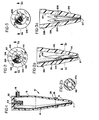
- Fig. 1 is a sectional view of a typical cyclone separator having a rejects outlet;
- Figs. 2, 3, 4 and 5 are top elevational views looking down into cyclone separator rejects outlets;
- Figs. 2a, 3a, 4a, and 5a are sectional side views of the respective rejects outlets; and
- Fig. 2b is a sectional view taken along
line 2b--2b in Fig. 2a. - Referring to Fig. 1, a typical cyclone separation device is illustrated. Of course, the invention is not limited to single devices including reverse centrifugal cleaning devices but is equally applicable to cluster arrangements. The apparatus includes a hollow cyclone member 10 forming a separation chamber having a
cylindrical portion 12, a tapering portion 14, and a hollow apex cone ortip portion 16 which has anoutlet port 17. The cylindrical and tapering portions of the cyclone body may be formed of a polymeric resin material such as polypropylene, polystyrene, nylon, or the like. Theapex tip portion 16 is preferably formed of a ceramic material which resists abrasion, although it may also be formed as a unitary structure with the cyclone body out of the same material as the body is formed. - The
cylindrical portion 12 of the cyclone has a tangentially extending slot-like inlet 18 through which a fluid suspension of material, such as paper stock, will enter the apparatus. The end ofcylindrical portion 12 of the cyclone body is provided with aclosure cover 20 which may be fabricated of the same polymeric resin material as other portions of cyclone member 10.Closure cover 20 and the end ofcylindrical portion 12 may be threaded for sealing engagement.Closure cover 20 is also provided with a centrally located vortex finder oroverflow nozzle tube 22 through which the accepts portion of the suspension flows and which extends inwardly into the center ofcylindrical portion 12. - Cyclone member 10 includes an
apex tip portion 16 which is preferably formed of an abrasion resistant cast ceramic material. The taperingtip portion 16 forms an extension of tapering portion 14, and can be formed with an outwardly projecting threadedportion 26 as an original part thereof for receiving an annular internally threadedcoupling nut 28 to sealtip portion 16 to tapering portion 14. Alternatively, the threaded portion may be cemented in place on thetip portion 16 in a known manner. - Figs. 2, 2a and 2b illustrate an embodiment of the invention in which apex tip portion l16 has an
outlet port 117 having a square cross-section. As shown, apex tip l16 is designed to be a replaceable element which can be joined to a cyclone separatorbody using threads 126. - As shown in Figs. 2, 2a, and 2b, the
inner wall 101 of the hollow tapering body portion ofapex tip 116 gradually transforms from circular to square cross-section a portion of the distance along the length of the tip. Taperingwall portions apex tip 116 during its fabrication (as illustrated) or may be secured in position after formation of the apex tip by suitable means. It has been found that the performance of the tip, which is improved by the use of an outlet of noncircular cross-section, is even further enhanced when at least a portion of the inner wall of the tip leading to the outlet gradually assumes the same cross-sectional configuration as the outlet, as best shown in Fig. 2b, whereopening 117b has started to assume a square cross-section. The exact amount and angle of taper will depend on many factors including the initial size and diameter of the cyclone separator and the desired cross-sectional area of the outlet opening. - It will of course be recognized that different portions of
inner wall 101 will have differing angles of taper. That is, as the cross-section of the separator is gradually transformed from circular to noncircular, certain wall portions will form lesser angles with the longitudinal axis of separator than other wall portions. For example, as illustrated in Figs. 2, 2a, and 2b, taperingwall portions wall portions - On the other hand, if a different manufacturing process is utilized and certain portions of.the inner wall of the separator are removed, for example, to produce a nominal 5/16" (0.8 cm) square outlet from the same diameter circular outlet, then the inner wall portions located along lines ending at each of the four corners of the finished outlet will form greater angles with the longitudinal axis of the separator than other wall portions since portions of the inner wall will be removed. When it is stated in this specification that the internal wall of the separator gradually transforms from a circular to a noncircular configuration, that expression is meant to cover both of the situations described above.
- In another embodiment of the invention illustrated in Figs. 3 and 3a,
apex tip portion 216 has anoutlet portion 217 having a triangular cross-section.Tip 216, as shown, is designed to be joined to a cyclonebody using threads 226.Inner wall 201 oftip 216 changes from a circular to a triangular cross-section a portion of the distance along the length of the tip. Taperingwall portions - The embodiment of the invention shown in Figs. 4 and 4a illustrates the use.of an oblong or
elliptical outlet port 317 inapex tip 316. The elliptically-shaped outlet results from the formation of the end oftip 316 at an angle a from the axis normal to the long axis of the tip. The angle a may be varied from 10 to 890 to vary the extent thatoutlet portion 317 deviates from a circular cross-section. Alternatively, thetip 316 may be formed with an elliptically-shaped outlet having an end normal to the long axis of the tip. As before,tip 316 may includethreads 326 to secure it to a cyclone body. - The embodiment of the invention shown in Figs. 5 and 5a illustrates the use of a polygonal or saw-toothed
shaped outlet portion 417 in anapex tip 416 designed to be joined to a cyclonebody using threads 426.Inner wall 401 oftip 416 changes from a circular to a polygonal cross-section a portion of the distance along the length of the tip. Taperingwall portions outlet 417. - In order that the invention may be better understood, reference is made to the following nonlimiting examples.
- Several tests were run using as the feedstock a deink stock from the third stage rejects of a cyclone separator system. A 3" (7.62 cm) diameter Cellu-Clone cyclone cleaner, available from The Black Clawson Company, Middletown, Ohio, was used for the tests. Four different rejects tips were tested as follows:
- 1. Standard tip-circular cross-section, 0.36" (0.9 cm) diameter (0.103 sq. in. [0.66 cm21 open area)
- 2. Tip A - circular cross-section, 0.25" (0.63 cm) diameter (0.049 sq. in. [0.32 cm2| open area)
- 3. Tip B - square cross-section, 0.25" (0.63 cm) sides, tapered (0.063 sq. in. [0.41 cm21 open area)
- 4. Tip C - oblong cross-section, 0.173" (0.44 cm) x 0.365" (0.93 cm) (0.063 sq. in. [0.41 cm21 open area).
- The results are reported in Table I below. In Runs 1-4, reject flow was controlled by a reject valve present in the cyclone separator device. Runs 5-8 were performed with the reject valve wide open to eliminate any possibility of plugging of the valve. An arrangement to provide free discharge was set up so that the rejects from the device discharged into an open pipe located approximately 8 feet (2.44 cm) above the device. This arrangement provided approximately 3.5 psi (0.235 bar) back pressure on the reject stock. The pressure drop measured through the device was 20 psi (1.34 bar) for all runs.

- As can be seen, Runs 3 and 7 performed with square tip B resulted in significantly lower reject rates and thickening factors than the standard circular tip (Runs 1 and 5) or tip A (Runs 2 and 6). Visual observation indicated that cleaning efficiency was substantially the same for all tips. No plugging of any tips occurred. Oblong tip C (Runs 4 and 8) exhibited a significantly greater thickening factor indicating its utility in situations where a higher consistency rejects stream is desired.
- The same arrangement as in Example 1 was used to test the tips except that the feedstock utilized was a mixture of Kraft corrugated furnish, clippings, and pieces. The results are reported in Table II below. Again, the pressure drop through the device was measured to be 20 psi (1.34 bar) for all runs.

- Again, square tip B (Run 10) operated at significantly lower reject rate than the standard circular tip (Run 9). No plugging occurred, and cleaning efficiencies for all tips appeared to be substantially the same. As before, oblong tip C (Run 11) exhibited a significantly higher thickening factor than the standard circular tip.
- Further test runs were made using the feedstock of Example 1 at a higher consistency (i.e., approximately 1.0%). The results are reported in Table III below. The pressure drop measured through the device was 20 psi (1.34 bar), for all runs.

- Again, even at higher feed consistencies, the square tip B (Run 12) exhibited a significantly lower reject rate as well as a lower thickening factor. Again, no plugging was observed.
- Further test runs were made using the feedstock of Example 1. A new tip was also tested as follows:
- Tip D - square cross-section, 0.25" (0.64 cm) sides, no taper (0.063 sq. in. [0.41 cm21 open area)
- The tests show the improved operating performance when using tapered sides in a square tip (Runs 17, 18, 19, 20 and 22) versus no taper (Run 16). However, the no taper tip D (Run 16) still operated at a lower reject rate than the standard circular tip (Run 21). Thickening factors were again lower for square versus circular tips. No plugging occurred.
- Thus, by utilizing a rejects outlet of noncircular cross-section in a cyclone separator as taught by the present invention, the rejects rate, thickening factor, and feed pressure to the device can also be varied to yield improved performance of the device while maintaining substantially the same cleaning efficiency and without plugging problems. For example, a lower rejects rate can be obtained using the same open area for a square tip versus prior art circular tips. If plugging is a problem, larger open area square tips can be used at substantially the same reject rates as prior art circular tips. Other modifications of tip geometry will be readily apparent to the skilled practitioner to achieve optimum performance under varying conditions of feed, pressure, consistency, and the like.
- While the apparatus herein described constitutes preferred embodiments of the invention, it is to be understood that the invention is not limited to this precise apparatus, and that changes may be made without departing from the scope of the invention, which is defined in the appended claims.

Claims (11)
1. In a cyclone separator (10) comprising means forming a separation chamber, a first end thereof (12) having a generally circular cross-section and including a tangential inlet (18) and central outlet (22), the opposite end thereof (14) tapering toward an outlet (17) of smaller flow area than said chamber, characterized by wall means (102, 104, 106, 108) defining an outlet having a non-circular cross-section.
2. A cyclone separator as claimed in claim 1 wherein said outlet has a square cross-section.
3. A cyclone separator as claimed in claim 1 wherein said outlet has a triangular cross-section.
4. A cyclone separator as claimed in claim 1 wherein said outlet has a polygonal cross-section.
5. A cyclone separator as claimed in claim 1 wherein said outlet has an oblong cross-section.
6. A cyclone separator as claimed in claims 1, 2, 3, 4, or 5 wherein at least a portion of the internal wall (101) of said opposite end of said separation chamber (14) gradually transforms to the same cross-section as said outlet.
7. The apex tip (16) of a cyclone separator characterized by a hollow tapering body portion having an internal wall (101) which gradually transforms from a circular cross-section near the inlet end thereof into a noncircular cross-section at the outlet (17) end thereof.
8. An apex tip as claimed in claim 7 wherein said outlet has a square cross-section.
9. An apex tip as claimed in claim 7 wherein said outlet has a triangular cross-section.
10. An apex tip as claimed in claim 7 wherein said outlet has a polygonal cross-section.
11. An apex tip as claimed in claim 7 wherein said outlet has an oblong cross-section.
Applications Claiming Priority (2)
| Application Number | Priority Date | Filing Date | Title |
|---|---|---|---|
| US32283181A | 1981-11-19 | 1981-11-19 | |
| US322831 | 1994-10-18 |
Publications (2)
| Publication Number | Publication Date |
|---|---|
| EP0080036A2 true EP0080036A2 (en) | 1983-06-01 |
| EP0080036A3 EP0080036A3 (en) | 1985-05-22 |
Family
ID=23256626
Family Applications (1)
| Application Number | Title | Priority Date | Filing Date |
|---|---|---|---|
| EP82108633A Withdrawn EP0080036A3 (en) | 1981-11-19 | 1982-09-18 | Noncircular rejects outlet for cyclone separator |
Country Status (6)
| Country | Link |
|---|---|
| EP (1) | EP0080036A3 (en) |
| JP (1) | JPS5889958A (en) |
| BR (1) | BR8206317A (en) |
| CA (1) | CA1203779A (en) |
| ES (1) | ES8400256A1 (en) |
| FI (1) | FI69410C (en) |
Cited By (1)
| Publication number | Priority date | Publication date | Assignee | Title |
|---|---|---|---|---|
| CN114985127A (en) * | 2022-07-15 | 2022-09-02 | 中国空气动力研究与发展中心低速空气动力研究所 | Method for changing jet flow shape |
Families Citing this family (2)
| Publication number | Priority date | Publication date | Assignee | Title |
|---|---|---|---|---|
| CA1231320A (en) * | 1984-06-04 | 1988-01-12 | Elp Products Ltd. | Self-sealing unplugging-probe admitting grommet for hydrocyclone reject outlets |
| DE202006003421U1 (en) * | 2006-03-04 | 2006-05-04 | Voith Paper Patent Gmbh | Device for discharging heavy parts from an apparatus for treating a pulp suspension, in particular from a hydrocyclone operable to clean a pulp suspension |
Citations (9)
| Publication number | Priority date | Publication date | Assignee | Title |
|---|---|---|---|---|
| US441140A (en) * | 1890-11-25 | culver | ||
| US479231A (en) * | 1892-07-19 | Pieter van gelder | ||
| FR341369A (en) * | 1904-03-01 | 1904-08-06 | Thomas Edward Wilson Clyma | Improvements to devices of the so-called "cyclone" type, intended to separate dust, waste, chips, etc., from the air |
| US3971718A (en) * | 1973-07-20 | 1976-07-27 | Elast-O-Cor Products & Engineering Limited | Hydrocyclone separator or classifier |
| US4163726A (en) * | 1977-04-29 | 1979-08-07 | Hughart Robert P | Valve assembly for cyclones or other abrasive applications |
| SU709181A1 (en) * | 1977-12-19 | 1980-01-15 | Киргизский сельскохозяйственный институт им.К.И.Скрябина | Hydrocycline |
| US4203834A (en) * | 1978-01-23 | 1980-05-20 | Krebs Engineers | Hydrocyclone underflow density control |
| GB2056325A (en) * | 1979-08-20 | 1981-03-18 | Enso Gutzeit Oy | Hydrocyclone |
| DE2942099A1 (en) * | 1979-10-18 | 1981-04-30 | Schauenburg Maschinen- und Anlagen-Bau GmbH, 4330 Mülheim | Cut-off point in cyclone classifier - controlled by intermediate laterally deformable nozzle |
Family Cites Families (2)
| Publication number | Priority date | Publication date | Assignee | Title |
|---|---|---|---|---|
| JPS5242442U (en) * | 1975-09-19 | 1977-03-25 | ||
| SE412529B (en) * | 1977-03-07 | 1980-03-10 | Celleco Ab | DEVICE OF A HYDROCYCLYCLONE Separator TO REDUCE THE RISK OF LOSS OF EASY FRACTION AND SETTLEMENT OF THE HEAVY FRACTION OUTPUT |
-
1982
- 1982-08-24 CA CA000409983A patent/CA1203779A/en not_active Expired
- 1982-09-18 EP EP82108633A patent/EP0080036A3/en not_active Withdrawn
- 1982-10-18 JP JP18266982A patent/JPS5889958A/en active Granted
- 1982-10-29 BR BR8206317A patent/BR8206317A/en unknown
- 1982-11-18 ES ES517475A patent/ES8400256A1/en not_active Expired
- 1982-11-18 FI FI823961A patent/FI69410C/en not_active IP Right Cessation
Patent Citations (9)
| Publication number | Priority date | Publication date | Assignee | Title |
|---|---|---|---|---|
| US441140A (en) * | 1890-11-25 | culver | ||
| US479231A (en) * | 1892-07-19 | Pieter van gelder | ||
| FR341369A (en) * | 1904-03-01 | 1904-08-06 | Thomas Edward Wilson Clyma | Improvements to devices of the so-called "cyclone" type, intended to separate dust, waste, chips, etc., from the air |
| US3971718A (en) * | 1973-07-20 | 1976-07-27 | Elast-O-Cor Products & Engineering Limited | Hydrocyclone separator or classifier |
| US4163726A (en) * | 1977-04-29 | 1979-08-07 | Hughart Robert P | Valve assembly for cyclones or other abrasive applications |
| SU709181A1 (en) * | 1977-12-19 | 1980-01-15 | Киргизский сельскохозяйственный институт им.К.И.Скрябина | Hydrocycline |
| US4203834A (en) * | 1978-01-23 | 1980-05-20 | Krebs Engineers | Hydrocyclone underflow density control |
| GB2056325A (en) * | 1979-08-20 | 1981-03-18 | Enso Gutzeit Oy | Hydrocyclone |
| DE2942099A1 (en) * | 1979-10-18 | 1981-04-30 | Schauenburg Maschinen- und Anlagen-Bau GmbH, 4330 Mülheim | Cut-off point in cyclone classifier - controlled by intermediate laterally deformable nozzle |
Cited By (2)
| Publication number | Priority date | Publication date | Assignee | Title |
|---|---|---|---|---|
| CN114985127A (en) * | 2022-07-15 | 2022-09-02 | 中国空气动力研究与发展中心低速空气动力研究所 | Method for changing jet flow shape |
| CN114985127B (en) * | 2022-07-15 | 2022-11-01 | 中国空气动力研究与发展中心低速空气动力研究所 | Method for changing jet flow shape |
Also Published As
| Publication number | Publication date |
|---|---|
| FI823961L (en) | 1983-05-20 |
| FI69410C (en) | 1986-02-10 |
| CA1203779A (en) | 1986-04-29 |
| JPH0322220B2 (en) | 1991-03-26 |
| EP0080036A3 (en) | 1985-05-22 |
| FI69410B (en) | 1985-10-31 |
| ES517475A0 (en) | 1983-11-01 |
| JPS5889958A (en) | 1983-05-28 |
| ES8400256A1 (en) | 1983-11-01 |
| BR8206317A (en) | 1983-09-20 |
| FI823961A0 (en) | 1982-11-18 |
Similar Documents
| Publication | Publication Date | Title |
|---|---|---|
| US7404492B2 (en) | Separation of fibre pulp suspensions containing relatively heavy contaminants | |
| EP0493950A2 (en) | Centrifugal cleaner | |
| EP0017481B1 (en) | Self-sealing valve assembly to facilitate unplugging of a centrifugal cleaner | |
| GB2056325A (en) | Hydrocyclone | |
| CA2148939C (en) | Adjustable hydrocyclone | |
| EP2448680B1 (en) | Hydrocyclone, system and method for cleaning cellulose suspensions | |
| JPH0330420B2 (en) | ||
| US3433362A (en) | Cyclone purifier | |
| JPS6318447Y2 (en) | ||
| US4510056A (en) | Hydrocyclone separator | |
| WO2000029123A1 (en) | Through-flow hydrocyclone and three-way cleaner | |
| US4451358A (en) | Noncircular rejects outlet for cyclone separator | |
| US3612276A (en) | Vortex-type separator apparatus | |
| GB2263652A (en) | Hydrocyclone | |
| EP0928223B1 (en) | Through-flow cleaner with improved inlet section | |
| CA2120436A1 (en) | Flotation system | |
| EP0080036A2 (en) | Noncircular rejects outlet for cyclone separator | |
| US3543932A (en) | Vortex chamber reject control | |
| US4564443A (en) | Reverse centrifugal cleaning of paper making stock | |
| US2878934A (en) | Method and apparatus separating dirt from aqueous suspensions of pulp fibres | |
| CA1159404A (en) | Vortex separator with central tengential heavies outlet and upper-most lights outlets | |
| CZ285066B6 (en) | Apparatus for separating at least one substance from liquid or gaseous medium | |
| US5938926A (en) | Extended dwell reverse hydrocyclone cleaner | |
| US4392950A (en) | Centrifugal type cleaner | |
| EP0132141B1 (en) | Centrifugal cleaning of paper making stock |
Legal Events
| Date | Code | Title | Description |
|---|---|---|---|
| PUAI | Public reference made under article 153(3) epc to a published international application that has entered the european phase |
Free format text: ORIGINAL CODE: 0009012 |
|
| AK | Designated contracting states |
Designated state(s): DE FR GB SE |
|
| 17P | Request for examination filed |
Effective date: 19830823 |
|
| PUAL | Search report despatched |
Free format text: ORIGINAL CODE: 0009013 |
|
| AK | Designated contracting states |
Designated state(s): DE FR GB SE |
|
| 17Q | First examination report despatched |
Effective date: 19860505 |
|
| STAA | Information on the status of an ep patent application or granted ep patent |
Free format text: STATUS: THE APPLICATION IS DEEMED TO BE WITHDRAWN |
|
| 18D | Application deemed to be withdrawn |
Effective date: 19861115 |
|
| RIN1 | Information on inventor provided before grant (corrected) |
Inventor name: CHUPKA, DAVID E. |