US4451358A - Noncircular rejects outlet for cyclone separator - Google Patents
Noncircular rejects outlet for cyclone separator Download PDFInfo
- Publication number
- US4451358A US4451358A US06/531,191 US53119183A US4451358A US 4451358 A US4451358 A US 4451358A US 53119183 A US53119183 A US 53119183A US 4451358 A US4451358 A US 4451358A
- Authority
- US
- United States
- Prior art keywords
- outlet
- section
- cyclone separator
- separator
- rejects
- Prior art date
- Legal status (The legal status is an assumption and is not a legal conclusion. Google has not performed a legal analysis and makes no representation as to the accuracy of the status listed.)
- Expired - Lifetime
Links
- 238000000926 separation method Methods 0.000 claims description 14
- 239000000725 suspension Substances 0.000 claims description 8
- 239000000463 material Substances 0.000 claims description 6
- 239000012530 fluid Substances 0.000 claims description 5
- 230000008719 thickening Effects 0.000 abstract description 13
- 238000004140 cleaning Methods 0.000 abstract description 9
- 239000000835 fiber Substances 0.000 description 11
- 239000012535 impurity Substances 0.000 description 4
- 239000000123 paper Substances 0.000 description 4
- 239000002245 particle Substances 0.000 description 4
- 239000007789 gas Substances 0.000 description 3
- 239000013055 pulp slurry Substances 0.000 description 3
- 229920001131 Pulp (paper) Polymers 0.000 description 2
- 238000005299 abrasion Methods 0.000 description 2
- 230000015572 biosynthetic process Effects 0.000 description 2
- 229910010293 ceramic material Inorganic materials 0.000 description 2
- 238000004519 manufacturing process Methods 0.000 description 2
- 239000002952 polymeric resin Substances 0.000 description 2
- 239000007787 solid Substances 0.000 description 2
- 229920003002 synthetic resin Polymers 0.000 description 2
- 229920003043 Cellulose fiber Polymers 0.000 description 1
- 108010076282 Factor IX Proteins 0.000 description 1
- 108010080865 Factor XII Proteins 0.000 description 1
- 102000000429 Factor XII Human genes 0.000 description 1
- 239000004677 Nylon Substances 0.000 description 1
- 239000004743 Polypropylene Substances 0.000 description 1
- 239000004793 Polystyrene Substances 0.000 description 1
- 239000000356 contaminant Substances 0.000 description 1
- 230000008878 coupling Effects 0.000 description 1
- 238000010168 coupling process Methods 0.000 description 1
- 238000005859 coupling reaction Methods 0.000 description 1
- 230000000694 effects Effects 0.000 description 1
- 239000002655 kraft paper Substances 0.000 description 1
- 239000007788 liquid Substances 0.000 description 1
- 239000000203 mixture Substances 0.000 description 1
- 238000012986 modification Methods 0.000 description 1
- 230000004048 modification Effects 0.000 description 1
- 229920001778 nylon Polymers 0.000 description 1
- -1 polypropylene Polymers 0.000 description 1
- 229920001155 polypropylene Polymers 0.000 description 1
- 229920002223 polystyrene Polymers 0.000 description 1
- 239000004576 sand Substances 0.000 description 1
- 238000007789 sealing Methods 0.000 description 1
- 239000002002 slurry Substances 0.000 description 1
- 230000000007 visual effect Effects 0.000 description 1
- XLYOFNOQVPJJNP-UHFFFAOYSA-N water Substances O XLYOFNOQVPJJNP-UHFFFAOYSA-N 0.000 description 1
Images

Classifications
-
- B—PERFORMING OPERATIONS; TRANSPORTING
- B04—CENTRIFUGAL APPARATUS OR MACHINES FOR CARRYING-OUT PHYSICAL OR CHEMICAL PROCESSES
- B04C—APPARATUS USING FREE VORTEX FLOW, e.g. CYCLONES
- B04C5/00—Apparatus in which the axial direction of the vortex is reversed
- B04C5/14—Construction of the underflow ducting; Apex constructions; Discharge arrangements ; discharge through sidewall provided with a few slits or perforations
-
- D—TEXTILES; PAPER
- D21—PAPER-MAKING; PRODUCTION OF CELLULOSE
- D21D—TREATMENT OF THE MATERIALS BEFORE PASSING TO THE PAPER-MAKING MACHINE
- D21D5/00—Purification of the pulp suspension by mechanical means; Apparatus therefor
- D21D5/18—Purification of the pulp suspension by mechanical means; Apparatus therefor with the aid of centrifugal force
- D21D5/24—Purification of the pulp suspension by mechanical means; Apparatus therefor with the aid of centrifugal force in cyclones
Definitions
- the present invention relates to apparatus for separating suspensions of solid particles in fluids, including both gases and liquids, into light and heavy fractions, and in particular to the separation of undesired particles from paper pulp slurries.
- Vortex or cyclone cleaners for separating sand, grit, bark particles, and shives from cellulose fibers in a paper pulp slurry.
- such cleaners include an elongated chamber of circular cross-section, either cylindrically shaped or somewhat tapered.
- the pulp slurry to be cleaned is introduced under pressure into one end of the chamber through a restricted tangential inlet so that a high velocity vortex is developed along the length of the chamber.
- the vortex is typically of a velocity high enough to form a centrally-located axial gas core in the chamber.
- the end of the chamber opposite the inlet is tapered and forms a relatively small diameter apex discharge outlet for the denser and larger particle rejects portion of the pulp slurry.
- Acceptable fibers which are of a relatively lower density and are located near the inner portion of the vortex, reverse their direction of flow adjacent the tapered end of the chamber and flow upwardly to be withdrawn through an axial outlet at the larger diameter end of the chamber.
- a cyclone separator system includes several stages coupled in series, with each stage including several separators connected in parallel, having common inlet and outlet chambers.
- the second stage treats the rejects of the first
- the third stage treats the rejects of the second, and so on, in an effort to minimize the amount of discarded good fibers while concentrating the impurities.
- Such a system is utilized to separate the original highly diluted pulp suspension into a usable paper making fiber portion (a lower density accepts portion) and a thickened large and denser impurities portion (rejects).
- An increase in the rejects flow from a cyclone separator system can result in the more complete removal of contaminants and impurities from the pulp suspension.
- increased rejects flows result in greater power requirements for the system to handle and transport greater volumes of material.
- increased rejects flows increase the amount of good fiber which is discarded from the system.
- the present invention meets that need by providing a cyclone separation device in which the internal wall of the device gradually transforms from a circular cross-section into a rejects discharge outlet which is noncircular in cross-section. It has been discovered that by varying the shape of the rejects outlet of a cyclone separator, the rejects rate, the thickening factor, and the feed pressure to the device can also be varied while maintaining substantially the same cleaning efficiency without plugging problems.
- the modified rejects outlet of the present invention may be incorporated or formed as an integral part of a conventional cyclone separation device or may be fabricated as a replaceable tip. Additionally, the present invention may be utilized in both single separator devices as well as in clusters of such devices.
- the modified rejects outlet of the present invention may also be used in conjunction with reverse centrifugal cleaning devices such as the device taught in Seifert et al, U.S. Pat. No. 4,155,839.
- the present invention may also be utilized in the separation of solids from gases.
- rejects rates i.e., the percentage of fiber in the rejects compared with the feed stock, without plugging, minimizing the loss of good fibers from the cleaner;
- the cleaning efficiency of cyclone separators using the present invention is substantially unaffected by the noncircular rejects outlets. This provides flexibility in the design of such cyclone separator systems to achieve one or more of the above operational advantages at no sacrifice in cleaning efficiency.
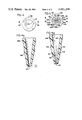
- FIG. 1 is a sectional view of a typical cyclone separator having a rejects outlet
- FIGS. 2, 3, 4 and 5 are top elevational views looking down into cyclone separator rejects outlets
- FIGS. 2a, 3a, 4a, and 5a are sectional side views of the respective rejects outlets.
- FIG. 2b is a sectional view taken along line 2b--2b in FIG. 2a.
- the apparatus includes a hollow cyclone member 10 forming a separation chamber having a cylindrical portion 12, a tapering portion 14, and a hollow apex cone or tip portion 16 which has an outlet port 17.
- the cylindrical and tapering portions of the cyclone body may be formed of a polymeric resin material such as polypropylene, polystyrene, nylon, or the like.
- the apex tip portion 16 is preferably formed of a ceramic material which resists abrasion, although it may also be formed as a unitary structure with the cyclone body out of the same material as the body is formed.
- the cylindrical portion 12 of the cyclone has a tangentially extending slot-like inlet 18 through which a fluid suspension of material, such as paper stock, will enter the apparatus.
- the end of cylindrical portion 12 of the cyclone body is provided with a closure cover 20 which may be fabricated of the same polymeric resin material as other portions of cyclone member 10. Closure cover 20 and the end of cylindrical portion 12 may be threaded for sealing engagement. Closure cover 20 is also provided with a centrally located vortex finder or overflow nozzle tube 22 through which the accepts portion of the suspension flows and which extends inwardly into the center of cylindrical portion 12.
- Cyclone member 10 includes an apex tip portion 16 which is preferably formed of an abrasion resistant cast ceramic material.
- the tapering tip portion 16 forms an extension of tapering portion 14, and can be formed with an outwardly projecting threaded portion 26 as an original part thereof for receiving an annular internally threaded coupling nut 28 to seal tip portion 16 to tapering portion 14.
- the threaded portion may be cemented in place on the tip portion 16 in a known manner.
- FIGS. 2, 2a and 2b illustrate an embodiment of the invention in which apex tip portion 116 has an outlet port 117 having a square cross-section. As shown, apex tip 116 is designed to be a replaceable element which can be joined to a cyclone separator body using threads 126.
- the inner wall 101 of the hollow tapering body portion of apex tip 116 gradually transforms from circular to square cross-section a portion of the distance along the length of the tip.
- Tapering wall portions 102, 104, 106, and 108 which together form a tapered passageway having a square cross-section, may be integrally molded into apex tip 116 during its fabrication (as illustrated) or may be secured in position after formation of the apex tip by suitable means.
- inner wall 101 will have differing angles of taper. That is, as the cross-section of the separator is gradually transformed from circular to noncircular, certain wall portions will form lesser angles with the longitudinal axis of separator than other wall portions. For example, as illustrated in FIGS. 2, 2a, and 2b, tapering wall portions 102, 104, 106, 108 will form lesser angles with the longitudinal axis of the separator than the wall portions 103, 105, 107 and 109 which are located between the tapering wall portions.
- apex tip portion 216 has an outlet portion 217 having a triangular cross-section.
- Tip 216 is designed to be joined to a cyclone body using threads 226.
- Inner wall 201 of tip 216 changes from a circular to a triangular cross-section a portion of the distance along the length of the tip.
- Tapering wall portions 202, 204, and 206 are provided which together form a tapering passageway having a triangular cross-section.
- FIGS. 4 and 4a illustrates the use of an oblong or elliptical outlet port 317 in apex tip 316.
- the elliptically-shaped outlet results from the formation of the end of tip 316 at an angle from the axis normal to the long axis of the tip. The angle may be varied from 1° to 89° to vary the extent that outlet portion 317 deviates from a circular cross-section.
- the tip 316 may be formed with an elliptically-shaped outlet having an end normal to the long axis of the tip.
- tip 316 may include threads 326 to secure it to a cyclone body.
- FIGS. 5 and 5a illustrates the use of a polygonal or saw-toothed shaped outlet portion 417 in an apex tip 416 designed to be joined to a cyclone body using threads 426.
- Inner wall 401 of tip 416 changes from a circular to a polygonal cross-section a portion of the distance along the length of the tip.
- Tapering wall portions 402, 403, 404, 405, 406, 407, 408, 409, 410, 411, 412, 413, 414, 415, 419 and 420 together form a tapering passageway having a polygonal cross-section and giving a saw-toothed effect to the outlet 417.
- Runs 1-4 reject flow was controlled by a reject valve present in the cyclone separator device. Runs 5-8 were performed with the reject valve wide open to eliminate any possibility of plugging of the valve. An arrangement to provide free discharge was set up so that the rejects from the device discharged into an open pipe located approximately 8 feet above the device. This arrangement provided approximately 3.5 psi back pressure on the reject stock. The pressure drop measured through the device was 20 psi for all runs.
- Runs 3 and 7 performed with square tip B resulted in significantly lower reject rates and thickening factors than the standard circular tip (Runs 1 and 5) or tip A (Runs 2 and 6).
- Example 2 The same arrangement as in Example 1 was used to test the tips except that the feedstock utilized was a mixture of Kraft corrugated furnish, clippings, and pieces. The results are reported in Table II below. Again, the pressure drop through the device was measured to be 20 psi for all runs.
- Example 1 Further test runs were made using the feedstock of Example 1 at a higher consistency (i.e., approximately 1.0%). The results are reported in Table III below. The pressure drop measured through the device was 20 psi, for all runs.
- no taper it is meant that the walls of the tip were parallel, rather than tapering inwardly.
- tip D was modified to give it tapered walls much like tip B. The results of the tests are reported in Table IV below. The pressure drop through the device was measured to be 20 psi for all runs.
- the rejects rate, thickening factor, and feed pressure to the device can also be varied to yield improved performance of the device while maintaining substantially the same cleaning efficiency and without plugging problems.
- a lower rejects rate can be obtained using the same open area for a square tip versus prior art circular tips. If plugging is a problem, larger open area square tips can be used at substantially the same reject rates as prior art circular tips.
- Other modifications of tip geometry will be readily apparent to the skilled practitioner to achieve optimum performance under varying conditions of feed, pressure, consistency, and the like.
Landscapes
- Engineering & Computer Science (AREA)
- Mechanical Engineering (AREA)
- Cyclones (AREA)
Abstract
Description
                                  TABLE I
__________________________________________________________________________
       Consistency                         Inlet
                                                Reject
Reject Feed         Flow Rates, GPM
                               Pulp Flow, O.D. T/D
                                           Pressure
                                                Rate Temp.
                                                         Thickening
Run
   Tip (Calc.)
           Accept
                Reject
                    Feed
                       Accept
                           Reject
                               Feed
                                  Accept
                                      Reject
                                           (PSI)
                                                % BOP
                                                     °F.
                                                         Factor
__________________________________________________________________________
1  STD 0.71
           0.61 3.29
                    44.0
                       42.4
                           1.6 1.87
                                  1.55
                                      .32  35   17.1%
                                                     88  4.63
2  A   0.56
           0.51 2.88
                    44.0
                       43.1
                           .9  1.48
                                  1.32
                                      .16  35   10.8%
                                                     99  5.14
3  B   0.59
           0.56 2.38
                    43.0
                       42.34
                           .66 1.51
                                  1.42
                                      .09  35   6.0% 100 4.03
4  C   0.55
           0.47 3.28
                    44.0
                       42.7
                           1.3 1.46
                                  1.20
                                      .26  35   17.8%
                                                     115 5.96
5  STD 0.62
           0.52 2.99
                    42.0
                       40.3
                           .7  1.57
                                  1.26
                                      .31  34   19.8%
                                                     76  4.82
6  A   0.59
           0.55 2.85
                    42.0
                       41.38
                           .62 1.48
                                  1.37
                                      .11  35   7.4% 84  4.83
7  B   0.59
           0.57 2.30
                    44.0
                       43.56
                           .44 1.55
                                  1.49
                                      .06  28   3.9% 86  3.90
8  C   0.55
           0.52 3.10
                    43.0
                       42.46
                           .54 1.43
                                  1.33
                                      .10  32   7.0% 87  5.64
__________________________________________________________________________
                                  TABLE II
__________________________________________________________________________
       Consistency                         Inlet
                                                Reject
Reject Feed         Flow Rates, GPM
                               Pulp Flow, O.D. T/D
                                           Pressure
                                                Rate Temp.
                                                         Thickening
Run
   Tip (Calc.)
           Accept
                Reject
                    Feed
                       Accept
                           Reject
                               Feed
                                  Accept
                                      Reject
                                           (PSI)
                                                % BOP
                                                     °F.
                                                         Factor
__________________________________________________________________________
 9 STD 0.53
           0.50 1.52
                    46 44.6
                           1.4 1.47
                                  1.34
                                      .13  32   8.9% 80  2.87
10 B   0.55
           0.54 1.60
                    48 47.5
                           .5  1.59
                                  1.54
                                      .05   251/2
                                                3.2% 87  2.90
11 C   0.51
           0.49 1.70
                    48 47.3
                           .7  1.46
                                  1.39
                                      .07  29   4.9% 92  3.33
__________________________________________________________________________
                                  TABLE III
__________________________________________________________________________
       Consistency                         Inlet
                                                Reject
Reject Feed         Flow Rates, GPM
                               Pulp Flow, O.D. T/D
                                           Pressure
                                                Rate Temp.
                                                         Thickening
Run
   Tip (Calc.)
           Accept
                Reject
                    Feed
                       Accept
                           Reject
                               Feed
                                  Accept
                                      Reject
                                           (PSI)
                                                % BOP
                                                     °F.
                                                         Factor
__________________________________________________________________________
12 B   0.93
           0.92 2.32
                    42 41.7
                           .3  2.34
                                  2.30
                                      .04  28   1.8% 64  2.50
13 STD 0.86
           0.82 2.88
                    43 42.06
                           .94 2.23
                                  2.07
                                      .16  32   7.3% 70  3.35
14 C   0.99
           0.96 3.08
                    42 41.4
                           .6  2.49
                                  2.38
                                      .11  31   4.5% 66  3.11
15 STD 0.93
           0.89 2.95
                    42 41.16
                           .84 2.35
                                  2.20
                                      .15  32   6.3% 70  3.17
__________________________________________________________________________
                                  TABLE IV
__________________________________________________________________________
       Consistency                              Reject
Reject Feed         Flow Rates, GPM
                                Pulp Flow, O.D. T/D
                                           Pressure
                                                Rate Temp.
                                                         Thickening
Run
   Tip (Calc.)
            Accept
                Reject
                    Feed
                       Accept
                            Reject
                                Feed
                                   Accept
                                       Reject
                                           Drop % BOP
                                                     °F.
                                                         Factor
__________________________________________________________________________
16 D   0.55 0.45
                3.75
                    44 42.75
                            1.25
                                1.43
                                   1.15
                                       .28 35   19.5%
                                                     96  6.8
17 B   0.55 0.50
                3.08
                    44 43.23
                            .77 1.44
                                   1.30
                                       .14 31   9.7% 96  5.6
18 B   0.56 0.53
                2.98
                    44 43.42
                            .58 1.48
                                   1.38
                                       .10 30   7.0% 103 5.3
19 D   0.56 0.52
                2.21
                    44 42.9 1.10
                                1.49
                                   1.34
                                       .15 30   9.8% 80  3.95
(modified)
20 B   0.52 0.49
                2.50
                    44 43.3 .7  1.38
                                   1.27
                                       .11  301/2
                                                7.6% 95  4.81
21 STD 0.48 0.35
                2.95
                    44 41.8 2.2 1.27
                                   .88 .39 37   30.7%
                                                     106 6.15
22 D   0.50 0.46
                2.43
                    44 43.1 .9  1.32
                                   1.19
                                       .13  301/2
                                                9.8% 115 4.86
(modified)
__________________________________________________________________________
Claims (9)
Priority Applications (1)
| Application Number | Priority Date | Filing Date | Title |
|---|---|---|---|
| US06/531,191 US4451358A (en) | 1981-11-19 | 1983-09-12 | Noncircular rejects outlet for cyclone separator |
Applications Claiming Priority (2)
| Application Number | Priority Date | Filing Date | Title |
|---|---|---|---|
| US32283181A | 1981-11-19 | 1981-11-19 | |
| US06/531,191 US4451358A (en) | 1981-11-19 | 1983-09-12 | Noncircular rejects outlet for cyclone separator |
Related Parent Applications (1)
| Application Number | Title | Priority Date | Filing Date |
|---|---|---|---|
| US32283181A Continuation | 1981-11-19 | 1981-11-19 |
Publications (1)
| Publication Number | Publication Date |
|---|---|
| US4451358A true US4451358A (en) | 1984-05-29 |
Family
ID=26983630
Family Applications (1)
| Application Number | Title | Priority Date | Filing Date |
|---|---|---|---|
| US06/531,191 Expired - Lifetime US4451358A (en) | 1981-11-19 | 1983-09-12 | Noncircular rejects outlet for cyclone separator |
Country Status (1)
| Country | Link |
|---|---|
| US (1) | US4451358A (en) |
Cited By (6)
| Publication number | Priority date | Publication date | Assignee | Title |
|---|---|---|---|---|
| US4655923A (en) * | 1985-05-23 | 1987-04-07 | Leone Vincent D | Desilter apparatus including adaptor members for accommodating connection of cyclone separators of any diameter to manifold conduits having invariant diameters |
| US5096066A (en) * | 1987-11-30 | 1992-03-17 | Genesis Research Corporation | Process for beneficiating particulate solids |
| US5153838A (en) * | 1987-11-30 | 1992-10-06 | Genesis Research Corporation | Process for beneficiating particulate solids |
| US20050102982A1 (en) * | 2002-02-16 | 2005-05-19 | Dummelow Anthony J. | Cyclonic separating apparatus |
| EP1830001A2 (en) * | 2006-03-04 | 2007-09-05 | Voith Patent GmbH | Device for discharging heavy parts from an apparatus for treating a pulp suspension, in particular from a hydrocyclone which can be operated to clean a pulp suspension |
| US20090188635A1 (en) * | 2008-01-28 | 2009-07-30 | Andritz Oy | Method and apparatus for treating pulp |
Citations (19)
| Publication number | Priority date | Publication date | Assignee | Title |
|---|---|---|---|---|
| BE531112A (en) * | 1953-08-13 | |||
| US1130802A (en) * | 1911-12-01 | 1915-03-09 | L B Allen Company | Fluid-holder. |
| US1595258A (en) * | 1925-10-03 | 1926-08-10 | Albert H Stebbins | Cyclone classifier |
| US1668271A (en) * | 1926-08-09 | 1928-05-01 | Charles R Fisk | Sprinkler |
| US1861247A (en) * | 1929-10-29 | 1932-05-31 | Albert H Stebbins | Air classifier |
| US1982733A (en) * | 1933-12-08 | 1934-12-04 | Forster Thomas Edgar | Air and dust separator |
| US2425710A (en) * | 1944-11-01 | 1947-08-19 | Linde Air Prod Co | Blowpipe nozzle |
| US2573192A (en) * | 1946-12-09 | 1951-10-30 | Directie Staatsmijnen Nl | Cyclone |
| US2897972A (en) * | 1956-03-28 | 1959-08-04 | Bird Machine Co | Separator |
| US2913112A (en) * | 1956-11-26 | 1959-11-17 | Dorr Oliver Inc | Hydrocyclone control |
| US2985384A (en) * | 1958-08-22 | 1961-05-23 | Byron H Martin | Hose nozzle and the like |
| US2999593A (en) * | 1956-11-12 | 1961-09-12 | Stern Hans | Classification of materials |
| US3042203A (en) * | 1959-08-17 | 1962-07-03 | J E T Pellet Mill Corp | Air-flow material separator |
| US3724674A (en) * | 1969-07-03 | 1973-04-03 | R Loison | Heads for hydrocyclonic separators |
| US3800946A (en) * | 1970-09-28 | 1974-04-02 | Elast O Car Prod & Eng Ltd | Hydrocyclones |
| US3971718A (en) * | 1973-07-20 | 1976-07-27 | Elast-O-Cor Products & Engineering Limited | Hydrocyclone separator or classifier |
| US4203834A (en) * | 1978-01-23 | 1980-05-20 | Krebs Engineers | Hydrocyclone underflow density control |
| US4216913A (en) * | 1978-12-04 | 1980-08-12 | Rain Bird Sprinkler Mfg. Corp. | Method and apparatus for enhancing the distribution of water from an irrigation sprinkler |
| US4224145A (en) * | 1977-12-02 | 1980-09-23 | Cellwood Grubbens Ab | Vortex cleaner |
-
1983
- 1983-09-12 US US06/531,191 patent/US4451358A/en not_active Expired - Lifetime
Patent Citations (19)
| Publication number | Priority date | Publication date | Assignee | Title |
|---|---|---|---|---|
| US1130802A (en) * | 1911-12-01 | 1915-03-09 | L B Allen Company | Fluid-holder. |
| US1595258A (en) * | 1925-10-03 | 1926-08-10 | Albert H Stebbins | Cyclone classifier |
| US1668271A (en) * | 1926-08-09 | 1928-05-01 | Charles R Fisk | Sprinkler |
| US1861247A (en) * | 1929-10-29 | 1932-05-31 | Albert H Stebbins | Air classifier |
| US1982733A (en) * | 1933-12-08 | 1934-12-04 | Forster Thomas Edgar | Air and dust separator |
| US2425710A (en) * | 1944-11-01 | 1947-08-19 | Linde Air Prod Co | Blowpipe nozzle |
| US2573192A (en) * | 1946-12-09 | 1951-10-30 | Directie Staatsmijnen Nl | Cyclone |
| BE531112A (en) * | 1953-08-13 | |||
| US2897972A (en) * | 1956-03-28 | 1959-08-04 | Bird Machine Co | Separator |
| US2999593A (en) * | 1956-11-12 | 1961-09-12 | Stern Hans | Classification of materials |
| US2913112A (en) * | 1956-11-26 | 1959-11-17 | Dorr Oliver Inc | Hydrocyclone control |
| US2985384A (en) * | 1958-08-22 | 1961-05-23 | Byron H Martin | Hose nozzle and the like |
| US3042203A (en) * | 1959-08-17 | 1962-07-03 | J E T Pellet Mill Corp | Air-flow material separator |
| US3724674A (en) * | 1969-07-03 | 1973-04-03 | R Loison | Heads for hydrocyclonic separators |
| US3800946A (en) * | 1970-09-28 | 1974-04-02 | Elast O Car Prod & Eng Ltd | Hydrocyclones |
| US3971718A (en) * | 1973-07-20 | 1976-07-27 | Elast-O-Cor Products & Engineering Limited | Hydrocyclone separator or classifier |
| US4224145A (en) * | 1977-12-02 | 1980-09-23 | Cellwood Grubbens Ab | Vortex cleaner |
| US4203834A (en) * | 1978-01-23 | 1980-05-20 | Krebs Engineers | Hydrocyclone underflow density control |
| US4216913A (en) * | 1978-12-04 | 1980-08-12 | Rain Bird Sprinkler Mfg. Corp. | Method and apparatus for enhancing the distribution of water from an irrigation sprinkler |
Cited By (11)
| Publication number | Priority date | Publication date | Assignee | Title |
|---|---|---|---|---|
| US4655923A (en) * | 1985-05-23 | 1987-04-07 | Leone Vincent D | Desilter apparatus including adaptor members for accommodating connection of cyclone separators of any diameter to manifold conduits having invariant diameters |
| US5096066A (en) * | 1987-11-30 | 1992-03-17 | Genesis Research Corporation | Process for beneficiating particulate solids |
| US5153838A (en) * | 1987-11-30 | 1992-10-06 | Genesis Research Corporation | Process for beneficiating particulate solids |
| US5280836A (en) * | 1987-11-30 | 1994-01-25 | Genesis Research Corporation | Process for beneficiating particulate solids |
| US20050102982A1 (en) * | 2002-02-16 | 2005-05-19 | Dummelow Anthony J. | Cyclonic separating apparatus |
| US7291190B2 (en) | 2002-02-16 | 2007-11-06 | Dyson Technology Limited | Cyclonic separating apparatus |
| CN101085430B (en) * | 2002-02-16 | 2010-12-15 | 戴森技术有限公司 | Cyclonic separating apparatus |
| EP1830001A2 (en) * | 2006-03-04 | 2007-09-05 | Voith Patent GmbH | Device for discharging heavy parts from an apparatus for treating a pulp suspension, in particular from a hydrocyclone which can be operated to clean a pulp suspension |
| EP1830001A3 (en) * | 2006-03-04 | 2008-07-23 | Voith Patent GmbH | Device for discharging heavy parts from an apparatus for treating a pulp suspension, in particular from a hydrocyclone which can be operated to clean a pulp suspension |
| US20090188635A1 (en) * | 2008-01-28 | 2009-07-30 | Andritz Oy | Method and apparatus for treating pulp |
| US7951263B2 (en) | 2008-01-28 | 2011-05-31 | Andritz Oy | Method and apparatus for treating pulp |
Similar Documents
| Publication | Publication Date | Title |
|---|---|---|
| US7404492B2 (en) | Separation of fibre pulp suspensions containing relatively heavy contaminants | |
| US5139652A (en) | Centrifugal cleaner | |
| US3391787A (en) | Porous cone cleaner | |
| US5240115A (en) | Field adjustable hydrocyclone | |
| US4356084A (en) | Self-sealing valve assembly to facilitate unplugging of a centrifugal cleaner | |
| GB2056325A (en) | Hydrocyclone | |
| JPH0330420B2 (en) | ||
| US6109451A (en) | Through-flow hydrocyclone and three-way cleaner | |
| US4797203A (en) | Reverse hydrocyclone cleaner for removing light contaminants from pulp slurry | |
| US3433362A (en) | Cyclone purifier | |
| JPS6318447Y2 (en) | ||
| US4510056A (en) | Hydrocyclone separator | |
| US4451358A (en) | Noncircular rejects outlet for cyclone separator | |
| EP0928223B1 (en) | Through-flow cleaner with improved inlet section | |
| US3612276A (en) | Vortex-type separator apparatus | |
| GB2263652A (en) | Hydrocyclone | |
| CA1203779A (en) | Noncircular rejects outlet for cyclone separator | |
| US4564443A (en) | Reverse centrifugal cleaning of paper making stock | |
| US3543932A (en) | Vortex chamber reject control | |
| CA1159404A (en) | Vortex separator with central tengential heavies outlet and upper-most lights outlets | |
| CZ285066B6 (en) | Apparatus for separating at least one substance from liquid or gaseous medium | |
| US5938926A (en) | Extended dwell reverse hydrocyclone cleaner | |
| US4392950A (en) | Centrifugal type cleaner | |
| EP0132141B1 (en) | Centrifugal cleaning of paper making stock | |
| CA1222220A (en) | Reverse centrifugal cleaning of paper making stock |
Legal Events
| Date | Code | Title | Description |
|---|---|---|---|
| STCF | Information on status: patent grant |
Free format text: PATENTED CASE |
|
| AS | Assignment |
Owner name: WALTER E. HELLER & COMPANY, INC., 101 PARK AVE., N Free format text: SECURITY INTEREST;ASSIGNOR:BLACK CLAWSON COMPANY, THE;REEL/FRAME:004250/0792 Effective date: 19840130 |
|
| FEPP | Fee payment procedure |
Free format text: PAYOR NUMBER ASSIGNED (ORIGINAL EVENT CODE: ASPN); ENTITY STATUS OF PATENT OWNER: LARGE ENTITY |
|
| AS | Assignment |
Owner name: BLACK CLAWSON COMPANY THE Free format text: RELEASED BY SECURED PARTY;ASSIGNOR:HELLER FINANCIAL, INC. F/K/A/ WALTER E. HELLER & COMPANY INC.;REEL/FRAME:004628/0875 Effective date: 19861015 |
|
| FPAY | Fee payment |
Year of fee payment: 4 |
|
| FPAY | Fee payment |
Year of fee payment: 8 |
|
| AS | Assignment |
Owner name: CENTRAL TRUST COMPANY, N.A., THE, OHIO Free format text: SECURITY INTEREST;ASSIGNORS:BLACK CLAWSON COMPANY, THE;BLACK CLAWSON CONVERTING LABORATORY, INC.;BLACK CLAWSON CONVERTING MACHINERY CORP.;AND OTHERS;REEL/FRAME:006385/0847 Effective date: 19921116 |
|
| FPAY | Fee payment |
Year of fee payment: 12 |
|
| AS | Assignment |
Owner name: BLACK CLAWSON COMPANY, THE, OHIO Free format text: RELEASE OF SECURITY INTEREST;ASSIGNOR:PNC BANK, OHIO, NATIONAL ASSOCIATION (FKA THE CENTRAL TRUST COMPANY, N.A.);REEL/FRAME:008215/0829 Effective date: 19951012 Owner name: BANK ONE, DAYTON, NATIONAL ASSOCIATION, OHIO Free format text: ASSIGNMENT OF ASSIGNORS INTEREST;ASSIGNOR:BLACK CLAWSON COMPANY, THE;REEL/FRAME:008215/0428 Effective date: 19961021 |
|
| AS | Assignment |
Owner name: BC ACQUISITION CORP., MASSACHUSETTS Free format text: ASSIGNMENT OF ASSIGNORS INTEREST;ASSIGNOR:BLACK CLAWSON COMPANY;REEL/FRAME:008650/0409 Effective date: 19970522 |
|
| AS | Assignment |
Owner name: THERMO BLACK CLAWSON INC., A CORPORATION OF DELAWA Free format text: CHANGE OF NAME;ASSIGNOR:BC ACQUISTION CORP., A CORPORATION OF DELAWARE;REEL/FRAME:008975/0178 Effective date: 19970523 |