EP0079385B1 - A shielded heating element and a method of manufacturing the same - Google Patents
A shielded heating element and a method of manufacturing the same Download PDFInfo
- Publication number
- EP0079385B1 EP0079385B1 EP82901434A EP82901434A EP0079385B1 EP 0079385 B1 EP0079385 B1 EP 0079385B1 EP 82901434 A EP82901434 A EP 82901434A EP 82901434 A EP82901434 A EP 82901434A EP 0079385 B1 EP0079385 B1 EP 0079385B1
- Authority
- EP
- European Patent Office
- Prior art keywords
- powder
- sheathed
- insulation resistance
- microns
- nickel oxide
- Prior art date
- Legal status (The legal status is an assumption and is not a legal conclusion. Google has not performed a legal analysis and makes no representation as to the accuracy of the status listed.)
- Expired
Links
Images


Classifications
-
- H—ELECTRICITY
- H05—ELECTRIC TECHNIQUES NOT OTHERWISE PROVIDED FOR
- H05B—ELECTRIC HEATING; ELECTRIC LIGHT SOURCES NOT OTHERWISE PROVIDED FOR; CIRCUIT ARRANGEMENTS FOR ELECTRIC LIGHT SOURCES, IN GENERAL
- H05B3/00—Ohmic-resistance heating
- H05B3/40—Heating elements having the shape of rods or tubes
- H05B3/42—Heating elements having the shape of rods or tubes non-flexible
- H05B3/48—Heating elements having the shape of rods or tubes non-flexible heating conductor embedded in insulating material
-
- H—ELECTRICITY
- H05—ELECTRIC TECHNIQUES NOT OTHERWISE PROVIDED FOR
- H05B—ELECTRIC HEATING; ELECTRIC LIGHT SOURCES NOT OTHERWISE PROVIDED FOR; CIRCUIT ARRANGEMENTS FOR ELECTRIC LIGHT SOURCES, IN GENERAL
- H05B3/00—Ohmic-resistance heating
- H05B3/10—Heater elements characterised by the composition or nature of the materials or by the arrangement of the conductor
Definitions
- This invention relates to a sheathed resistance heater which comprises a metal pipe receiving therein a heating wire and an electrically insulating powder packed in the metal pipe whereby the heater has a prolonged life and exhibits a high level of insulation resistance in a working condition after having been used over a long time.
- Sheathed resistance or electric heaters have been widely used in many fields because of their very excellent performance, quality and convenience, extending the commercial range including not only domestic electric articles, but also specific applications such as in various industries, space developments, atomic power services and the like.
- sheathed heaters for high temperature purposes are considered to have more and more increasing applications in the future.
- insulation resistance under self-heating conditions lowers as a function of time, coupled with another disadvantage that it takes only a short time 'before disconnection of the heating wire.
- DE-A-1 565 279 discloses the addition of nickel, iron or copper oxides to magnesia as a packing for a heating element in a metal tube.
- FR-A-1 192 367 is somewhat similar but has a ceramic tube not a metal one.
- US ⁇ A ⁇ 3 369 209 suggests addition of iron, nickel, copper and cobalt oxides, but for the purpose of reducing discoloration of the magnesia.
- a method of fabricating a sheathed resistance heater by filling a metal pipe into which a heating wire is inserted with an electrically insulating powder containing a nickel oxide powder, characterised in that fine nickel oxide particles which have been produced by roasting nickel sulphate or metallic nickel powder and which have a size below 5 microns are granulated into granules having a size below 250 microns and in that the granules are then mixed with insulating powder to provide 0.1-10 wt% of the mixture.
- a sheathed resistance heater comprising a casing into which a heating wire is inserted with an electrically insulating powder containing a nickel oxide powder characterised in that the electrically insulating powder contains 0.1-10 wt% of nickel oxide and in that the nickel oxide is in the form of granules, having a size below 250 microns, comprising particles of nickel oxide having a size less than 5 microns.
- the present invention thus provides a sheathed resistance heater and a method for fabricating the heater; in which the electrically insulating powder used is a powder admixed with the specific type of a powder whereby the heater has a prolonged life before breakage of the heating wire and exhibits high insulation resistance under self-heating conditions even after its long-term use.
- Figure 1 is a sectional view of an ordinary sheathed resistance heater; and Figures 2-6 refer to embodiments of the present invention, in which Figures 2, 5, 6 are characteristic graphs of the insulation resistance under self-heating conditions in relafion to variation in test period, Figure 3, is a characteristic graph of the insulation resistance under self-heating conditions in relation to variation in amounts of oxides, and Figure 4, is a characteristic graph of the life in relation to variation in amounts of oxides.
- a sheathed resistance heater comprises, as particularly shown in Figure 1, a coil-like heating wire 2 provided with terminal bars 1 at opposite ends thereof, a metal pipe 3 receiving the heating wire therein, and an electrically insulating powder 4 such as of electrofused magnesia, electrofused silica, electrofused alumina or the like which is filled up in the metal pipe.
- the metal pipe 3 may be sealed with a glass 5 and a heat-resistant resin 6 at opposite sides thereof.
- An electrofused magnesia powder was used as a main component of the electrically insulating powder 4, which was admixed with NiO in different amounts to obtain samples of electrically insulating powder 4.
- the electrofused magnesia powder had a composition indicated in Table 1 below.
- the heating wire 2 used was a nichrome wire of the first kind having a diameter of 0.29 mm and wound in the form of a coil with a winding diameter of 2 mm.
- the wire was connected with terminal bars 1 at opposite ends thereof.
- the metal pipe 3 used was a pipe, NCF2P (commercial name Incoroi 800), having a length of 413 mm, an outer diameter of 8 mm and a thickness of 0.46 mm.
- each of the metal pipes 3 was inserted the heating wire 2 provided with the terminal bars 1 at opposite ends. Thereafter, the electrically insulating powder 4 which had previously been prepared was filled up in the metal pipe 3, followed by subjecting the pipe to the steps of rolling for reducing the diameter and annealing (1050°C, 10 minutes) to make the length and outer diameter at 500 mm and 6.6 mm, respectively.
- the metal pipe 3 was sealed at opposite ends thereof with a low melting glass 5 and a heat-resistant resin 6. As a result, sheathed resistance heaters of sample Nos. 12-18 were fabricated.
- a conventional sheathed heater (sample No. 11) was made using an electrically insulating powder 4 consisting of the electrofused magnesia powder alone whose composition was shown in Table 1.
- the insulation resistance values of the respective samples 11 days after commencement of the continuous energizing test are shown in Table 2.
- the relation between the content of NiO and the insulation resistance value under self-heating conditions 11 days after commencement of the continuous energizing test is shown in Figure 3.
- the sheathed heaters of sample Nos. 12-16 in which there were used the electrically insulating powders having a NiO content of 0.1-10 wt% were less lowered in insulation resistance under self-heating conditions than the known sheathed heater numbered as 11.
- the sheathed heaters of sample Nos. 17 and 18 which made use of electrically insulating powders having NiO contents over 15 wt% had low initial insulation resistance values under self-heating conditions immediately after fabrication of the heaters and could not stand practical use.
- Figure 3 reveals that the sheathed heaters (sample Nos. 12-16) in which the content of NiO was in the range of 0.1-10 wt% exhibited higher insulation resistance values under self-heating conditions 11 days after commencement of the continuous energizing test than the known sheathed heater of sample No. 11.
- Figure 4 reveals that the sheathed heaters (sample Nos. 12-16) in which the content of NiO was in the range of 0.1-10 wt% was longer in life than the known sheathed heater of sample No. 11.
- the sheathed heaters which made use of electrically insulating powders admixed with NiO in amounts ranging from 0.1-10 wt% exhibited less lowered insulation resistance values under self-heating conditions and a prolonged life.
- electrofused magnesia powder was used as a main component of the electrically insulating powder in Example 1.
- a similar tendency results when using, instead of the electrofused - magnesia powder, electrofused alumina and silica powders.
- sheathed heater may vary depending on the type of an electrofused magnesia powder. For instance, when an electrofused magnesia powder having a high specific resistance is used, there can be obtained a sheathed resistance heater of higher insulation resistance. Use of a highly pure electrofused magnesia powder having a relatively long life results in a sheathed resistance heater of longer life.
- the nicrome wire of the first kind used as the heating wire 2 may be replaced by several wires indicated in Table 3 with similar results. As regards the metal pipe 3, similar results are obtained when using metallic materials indicated in Table 4.
- the metal tubes were sealed with the low melting glass 5 and the heat-resistant resin 6 in Example 1 but a similar tendency was shown even though the tubes were not sealed.
- the sheathed heater of the present invention is not limited to the design shown in Figure 1 and can include those heaters called cartridge and glow plug heaters.
- the electrofused magnesia powder should be uniformly mixed with oxides.
- primary particles of NiO powder are fine and coagulate into secondary particles, so that it is difficult to disperse the oxide uniformly.
- a metallic nickel powder, nickel nitrate, nickel carbonate, nickel oxalate, and nickel sulfate were roasted to obtain nickel oxide powders, respectively.
- An electrofused magnesia powder was provided as a main component of the electrically insulating powder 4 and admixed with each of the nickel oxide powders obtained above in an amount of 1 wt%. These mixtures were used as the electrically insulating powder 4.
- the electrofused magnesia powder used in this example had a composition indicated in table 5 below.
- the heating wire 2 used was a nichrome wire of the first kind having a diameter of 0.29 mm in the form of a coil having a winding diameter of 2 mm.
- the wire was connected with terminal bars 1 at opposite ends thereof.
- NCF 2P commercial name Incoroi 800
- NCF 2P commercial name Incoroi 800
- the heating wire 2 connected with the terminal bars at opposite ends thereof. Further, the electrically insulating powder 4 which had previously been prepared was filled up in the metal pipe 3, followed by the steps of rolling for reducing the pipe diameter and annealing (1050°C, 10 minutes) thereby making a metal pipe having a length of 500 mm and an outer diameter of 6.6 mm.
- the pipe was tightly sealed by the use of a low melting glass 5 and a heat-resistant resin 6 at opposite ends thereof to accomplish a sheathed resistance heater.
- a known sheathed resistance heater was made using an electrofused magnesia powder alone as the electrically insulating powder 4.
- the respective sheathed heaters were subjected to the measurement of an initial insulation resistance value at room temperature, insulation resistance value at a temperature on the pipe surface of 750°C (hereinafter referred to as insulation resistance under self-heating conditions), and dielectric strength at room temperature. Sheathed resistance heaters which had an insulation resistance under self-heating conditions of below 1 mega ohms and a dielectric strength below 1000 V were determined as defectives and a fraction defective of each group was calculated. The results are shown in Table 6.
- the sample 65 of the present invention showed such a low fraction defective as the sample 11 which made use of the electrically insulating powder 4 consisting of the electrofused magnesia powder alone.
- each sheathed heater was energized so that the surface temperature of the metal pipe 3 was maintained at a temperature of 950°C to determine the variation of the insulation resistance under self-heating conditions. It will be noted that when the insulation resistance under self-heating conditions was measured, the surface temperature was lowered down to 750°C.
- curves 65 and 11 correspond to the sample 65 of the invention and the sample 11 of the prior art embodiment, respectively.
- the sample 65 of the present invention had at least about 10 times the life of the known sample 11 and exhibited a higher value of the insulation resistance under self-heating conditions as measured 11 days after the continuous test.
- the electrofused magnesia powder was used as the electrically insulating powder but a similar tendency was shown when using, instead of the magnesia powder, electrofused alumina and silica powders.
- the nickel oxide powder is produced by roasting nickel sulfate and is admixed with the main component to give an electrically insulating powder useful in the present invention.
- a metallic nickel powder (average size 3p-7p) was roasted to 900°C for 2 hours and reduced into pieces having a size below 1 11 to give a nickel oxide powder.
- An electrofused magnesia powder used as a main component of the electrically insulating powder 4 was admixed with 1 wt% of the nickel oxide powder to obtain a mixed powder.
- This mixed powder was provided as electrically insulating powder 4.
- the electrofused magnesia powder, the heating wire and the metal pipe were same as used in Example 2.
- the heating wire 2 connected with the terminal bars at opposite ends thereof was inserted into the metal pipe 3, which was then filled up with the electrically insulating powder 4 which had been previously prepared.
- the pipe was subsequently subjected to the steps of rolling for reducing its diameter and annealing (1050°C, 10 minutes) to make a pipe of 500 mm in length and 6.6 mm in outer diameter.
- the metal pipe 3 was tightly sealed at opposite ends thereof with a low melting glass 5 and a heat-resistant resin 6 to accomplish a sheathed resistance heater of sample No. 66.
- the finished sheathed heaters were each subjected to the measurement of an insulation resistance at a pipe surface temperature of 750°C immediately after the fabrication, and also to the life and insulation resistance tests described in below.
- the heating wire of each of the sheathed heaters was energized so that the surface temperature of the metal pipe 3 was maintained at 950°C to check the number of days before disconnection of the wire.
- the heating wire 2 of each of the sheathed heaters was energized so that the surface temperature of the metal pipe 3 was maintained at 950°C to determine the variation of the insulation resistance under self-heating conditions. It will be noted that the measurement of the insulation resistance was effected after lowering the surface temperature of the metal pipe 3 down to 750°C.
- Table 8 there are shown the results of the insulation resistance under self-heating conditions measured immediately after the fabrication, and the life test and the insulation resistance under self-heating conditions measured after 11 days in the insulation resistance test. Moreover, the variation of the insulation resistance observed during the insulation resistance test is shown in Figure 6. In Figure 6, curves 66, 11 and 67 correspond to the inventive sheathed heater 66, and the known heaters 11 and 67, respectively.
- the nickel oxide powder prepared according to the invention With the embodiment of the invention in which the nickel oxide powder prepared according to the invention was used, its insulation resistance is smaller than that of the known sample 11 but is much higher than that of the known sample 67.
- the present invention is very effective.
- the nickel oxide powder of the invention gives a great effect: the life is at least about ten times longer than the life of the known sample 11 with the insulation resistance under self-heating conditions measured 11 days after the continuous test being also higher.
- the electrofused magnesia powder was used as a main component of the electrically insulating powder but a similar tendency is shown when using, instead of the electrofused magnesia powder, electrofused alumina and silica powders.
- the method of fabricating a sheathed resistance heater according to the invention is a method in which there is used an electrically insulating powder to which is added a nickel oxide powder produced by roasting metallic nickel powder.
- a metallic nickel powder (average particle 3 microns-7 microns) was roasted at 900°C for 2 hours and reduced to pieces to obtain nickel oxide particles.
- the nickel oxide particles were classified into three groups including a group of particles having a size over 10 microns, a group of particles having a size ranging from 10 microns-5 microns, and a group of particles having a size below 5 microns.
- the particles were granulated to a level of 250 microns using water as a binder to give nickel oxide granules.
- An electrofused magnesia powder was provided as a main component and admixed with 1 wt% of the nickel oxide granules prepared by the above method to give a sample electrically insulating powder 4.
- the electrofused magnesia powder, heating wire and metal pipe used in this example were same as those used in Example 2.
- the heating wire 2 connected with the terminal bars 1 at opposite ends thereof.
- the pipe was filled up with the electrically insulating powder 4, followed by the steps of rolling for reducing the diameter and annealing (1050°C, 10 minutes), with the result that it has a length of 500 mm and an outer diameter of 6.6 mm.
- the resulting pipe 3 was tightly sealed at opposite ends thereof with a low melting glass 5 and a heat-resistant resin 6 to accomplish a sheathed resistance heater of sample No. 68.
- a metallic nickel powder (average size 3 microns-7 microns) was roasted at 900°C for 2 hours and ground to a level of below 5 microns, after which the powder was granulated by the use of water as a binder to provide nickel oxide granules.
- the granulation was effected so that the size was classified into groups of 420 microns-350 microns, 350 microns-297 microns, 297 microns-250 microns, 250 microns-177 microns, 177 microns-105 microns and below 105 microns.
- Example 5 was repeated thereby obtaining sheathed resistance heaters numbered as 69.
- Nickel sulfate was crystallized from a nickel sulfate solution, after which the nickel sulfate crystals were roasted at 1000°C for 2 hours, followed by grinding to a level of below 5 microns.
- the powder was granulated using water as a binder to obtain particles having a size below 250 microns thereby providing a sample of nickel oxide granules.
- Example 5 was repeated to accomplish a sheathed resistance heater of sample No. 70.
- prior art sheathed resistance heaters including a heater making use of an electrofused magnesia powder as the electrically insulating powder 4 (sample No. 11) and a heater of sample No. 71 in which the an electrically insulating powder used was in admixture with 1 wt% of a commercially available nickel oxide powder which was produced from a starting metallic nickel powder.
- a sheathed resistance heater of sample No. 72 was fabricated in which there was used an electrofused magnesia powder admixed with 1 wt% of a commercially available nickel oxide produced from starting nickel sulfate.
- the sheathed resistance heaters fabricated in Examples 5-7 and the prior-art heaters were classified, as shown in Table 9, according to the size of the primary particles of the added nickel oxide particles and the size of the granulated particles.
- the respective sheathed resistance heaters were subjected to the measurement of an initial insulation resistance at room temperature immediately after their fabrication, insulation resistance at a temperature on the pipe surface of 750°C, and dielectric strength at room temperature. Sheathed heaters which had an insulation resistance under self-heating conditions of below 1 mega ohms and a dielectric strength of below 1000 V were determined as a defective and fraction defectives in the respective groups were calculated. The results are shown in Table 9.
- the sheathed heaters of Groups C, G, H, I, J and K whose fraction defectives are below 1% were further subjected to the life test and the insulation resistance test under self-heating conditions.
- the heating wire 2 of each heater was energized so that the surface temperature of the metal pipe 3 was maintained at 950°C to determine the number of days prior to disconnection of the wire 2.
- the heating wire 2 was energized so that the surface temperature of the metal pipe 3 was maintained at 950°C to determine a variation of insulation resistance. It will be noted that the measurement of the insulation resistance was effected after lowering the surface temperature of the metal pipe 3 down to 750°C.
- samples L and M in which the commercially available nickel oxide powders were used are much higher in fraction defective than sample K making use of the magnesia powder alone as the electrically insulating powder 4 but the size of the nickel oxide particles is below 5 microns.
- Samples C, G, H, I and J of Examples 5-7 in which the nickel oxide particles granulated to have sizes below 250 microns show almost the same level of fraction defective as sample K.
- nickel oxide particles may be present as larger-size particles, or may segregate in some portions of sheathed heater such as by vibrations occurring upon filling of the particles. These phenomena will cause very high fraction defectives with regard to the insulation resistance and particularly the dielectric strength, presenting serious problems in the fabrication of the heaters.
- samples C, G, H, I and J and the prior-art sample K which were low in fraction defective as particularly shown in Table 9 were subjected to the life and insulation resistance tests to compare the characteristics of these heaters with one another.
- the life was about 10 times as long as that of the heater K using the known magnesia powder alone and the insulation resistance values under self-heating conditions measured 11 days after commencement of the test were kept at high levels.
- Examples 5-7 the electrofused magnesia powder was used as a main component of the electrically insulating powder. In this connection, a similar tendency was found to be shown when using electrofused alumina and silica powders instead of the electrofused magnesia powder.
- the method of fabricating a sheathed resistance heater according to the invention is a method which comprises granulating nickel oxide particles ground to a level below 5 microns into granules having a size below 250 microns and adding the granules to an electrically insulating powder, with the result that there is stably provided a heater which has a long life and a high insulation resistance value under self-heating conditions after having been used over a long term.
Description
- This invention relates to a sheathed resistance heater which comprises a metal pipe receiving therein a heating wire and an electrically insulating powder packed in the metal pipe whereby the heater has a prolonged life and exhibits a high level of insulation resistance in a working condition after having been used over a long time.
- Sheathed resistance or electric heaters have been widely used in many fields because of their very excellent performance, quality and convenience, extending the commercial range including not only domestic electric articles, but also specific applications such as in various industries, space developments, atomic power services and the like. Among various classes of sheathed resistance heaters, sheathed heaters for high temperature purposes are considered to have more and more increasing applications in the future.
- Upon reviewing the performance and quality of sheathed resistance heters in a world-wide sense, they have drawbacks in that the insulation resistance of the heaters in a working condition (hereinafter referred to as insulation resistance under self-heating conditions) lowers as a function of time, coupled with another disadvantage that it takes only a short time 'before disconnection of the heating wire.
- DE-A-1 565 279 discloses the addition of nickel, iron or copper oxides to magnesia as a packing for a heating element in a metal tube. FR-A-1 192 367 is somewhat similar but has a ceramic tube not a metal one. US―A―3 369 209 suggests addition of iron, nickel, copper and cobalt oxides, but for the purpose of reducing discoloration of the magnesia.
- According to the present invention, there is provided a method of fabricating a sheathed resistance heater by filling a metal pipe into which a heating wire is inserted with an electrically insulating powder containing a nickel oxide powder, characterised in that fine nickel oxide particles which have been produced by roasting nickel sulphate or metallic nickel powder and which have a size below 5 microns are granulated into granules having a size below 250 microns and in that the granules are then mixed with insulating powder to provide 0.1-10 wt% of the mixture.
- A sheathed resistance heater comprising a casing into which a heating wire is inserted with an electrically insulating powder containing a nickel oxide powder characterised in that the electrically insulating powder contains 0.1-10 wt% of nickel oxide and in that the nickel oxide is in the form of granules, having a size below 250 microns, comprising particles of nickel oxide having a size less than 5 microns.
- The present invention thus provides a sheathed resistance heater and a method for fabricating the heater; in which the electrically insulating powder used is a powder admixed with the specific type of a powder whereby the heater has a prolonged life before breakage of the heating wire and exhibits high insulation resistance under self-heating conditions even after its long-term use.
- Figure 1 is a sectional view of an ordinary sheathed resistance heater; and Figures 2-6 refer to embodiments of the present invention, in which Figures 2, 5, 6 are characteristic graphs of the insulation resistance under self-heating conditions in relafion to variation in test period, Figure 3, is a characteristic graph of the insulation resistance under self-heating conditions in relation to variation in amounts of oxides, and Figure 4, is a characteristic graph of the life in relation to variation in amounts of oxides.
- Embodiments of the present invention are described with reference to the accompanying drawings.
- In general, a sheathed resistance heater comprises, as particularly shown in Figure 1, a coil-
like heating wire 2 provided withterminal bars 1 at opposite ends thereof, ametal pipe 3 receiving the heating wire therein, and an electrically insulatingpowder 4 such as of electrofused magnesia, electrofused silica, electrofused alumina or the like which is filled up in the metal pipe. Optionally, themetal pipe 3 may be sealed with aglass 5 and a heat-resistant resin 6 at opposite sides thereof. - We have paid particular attention to the electrically insulating
powder 4 and made extensive studies on the powder. - An electrofused magnesia powder was used as a main component of the electrically insulating
powder 4, which was admixed with NiO in different amounts to obtain samples of electrically insulatingpowder 4. - The electrofused magnesia powder had a composition indicated in Table 1 below.

- The
heating wire 2 used was a nichrome wire of the first kind having a diameter of 0.29 mm and wound in the form of a coil with a winding diameter of 2 mm. The wire was connected withterminal bars 1 at opposite ends thereof. Themetal pipe 3 used was a pipe, NCF2P (commercial name Incoroi 800), having a length of 413 mm, an outer diameter of 8 mm and a thickness of 0.46 mm. - Into each of the
metal pipes 3 was inserted theheating wire 2 provided with theterminal bars 1 at opposite ends. Thereafter, the electrically insulatingpowder 4 which had previously been prepared was filled up in themetal pipe 3, followed by subjecting the pipe to the steps of rolling for reducing the diameter and annealing (1050°C, 10 minutes) to make the length and outer diameter at 500 mm and 6.6 mm, respectively. Themetal pipe 3 was sealed at opposite ends thereof with alow melting glass 5 and a heat-resistant resin 6. As a result, sheathed resistance heaters of sample Nos. 12-18 were fabricated. - The content of NiO in the insulating powders used in the sheathed heaters of sample Nos. 12-18 is shown in Table 2.
- For comparison purposes, a conventional sheathed heater (sample No. 11) was made using an electrically insulating
powder 4 consisting of the electrofused magnesia powder alone whose composition was shown in Table 1. - In order to determine the insulation and life performances of each of the sheathed heaters numbered as 11-18, the following tests were conducted.
- First, the insulation resistance was measured, as an initial characteristic of sheathed heater, under conditions where the surface temperature of the metal pipe was 750°C. The results are shown in Table 2.
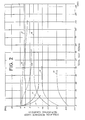
- The variation in the insulation resistance under self-heating conditions was measured by continuously energizing the
heating wire 2 so that the surface temperature of the metal pipe was maintained at 950°C. It will be noted here that at the time when the insulation resistance under self-heating conditions was measured, the surface temperature of themetal pipe 3 was lowered down to 750°C. The variation in the insulation resistance under self-heating conditions is shown in Figure 2. In Figure 2, curves 11-18 correspond to the sheathed heaters of sample Nos. 11-18, respectively. - The insulation resistance values of the
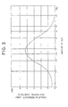
respective samples 11 days after commencement of the continuous energizing test are shown in Table 2. The relation between the content of NiO and the insulation resistance value under self-heating conditions 11 days after commencement of the continuous energizing test is shown in Figure 3. - The continuous test was further continued on each of the sheathed heaters numbered as 11-18 to determine the number of days (life) before the
heating wire 2 was disconnected. The test results are shown in Table 2 and the relation between the content of NiO and the life is shown in Figure 4.
- As will be apparent from the results of Table 2 and Figure 2, the sheathed heaters of sample Nos. 12-16 in which there were used the electrically insulating powders having a NiO content of 0.1-10 wt% were less lowered in insulation resistance under self-heating conditions than the known sheathed heater numbered as 11. The sheathed heaters of sample Nos. 17 and 18 which made use of electrically insulating powders having NiO contents over 15 wt% had low initial insulation resistance values under self-heating conditions immediately after fabrication of the heaters and could not stand practical use.
- Figure 3 reveals that the sheathed heaters (sample Nos. 12-16) in which the content of NiO was in the range of 0.1-10 wt% exhibited higher insulation resistance values under self-
heating conditions 11 days after commencement of the continuous energizing test than the known sheathed heater of sample No. 11. - *Moreover, Figure 4 reveals that the sheathed heaters (sample Nos. 12-16) in which the content of NiO was in the range of 0.1-10 wt% was longer in life than the known sheathed heater of sample No. 11.
- Thus, the sheathed heaters which made use of electrically insulating powders admixed with NiO in amounts ranging from 0.1-10 wt% exhibited less lowered insulation resistance values under self-heating conditions and a prolonged life.
- Moreover, the electrofused magnesia powder was used as a main component of the electrically insulating powder in Example 1. A similar tendency results when using, instead of the electrofused - magnesia powder, electrofused alumina and silica powders.
- The characteristics of sheathed heater may vary depending on the type of an electrofused magnesia powder. For instance, when an electrofused magnesia powder having a high specific resistance is used, there can be obtained a sheathed resistance heater of higher insulation resistance. Use of a highly pure electrofused magnesia powder having a relatively long life results in a sheathed resistance heater of longer life.
- The nicrome wire of the first kind used as the
heating wire 2 may be replaced by several wires indicated in Table 3 with similar results. As regards themetal pipe 3, similar results are obtained when using metallic materials indicated in Table 4.

- The metal tubes were sealed with the
low melting glass 5 and the heat-resistant resin 6 in Example 1 but a similar tendency was shown even though the tubes were not sealed. - The sheathed heater of the present invention is not limited to the design shown in Figure 1 and can include those heaters called cartridge and glow plug heaters.
- The electrofused magnesia powder should be uniformly mixed with oxides. In this connection, however, with NiO, primary particles of NiO powder are fine and coagulate into secondary particles, so that it is difficult to disperse the oxide uniformly. A method of fabricating a sheathed resistance heater which is suitable for overcoming the above difficulty is described.
- A metallic nickel powder, nickel nitrate, nickel carbonate, nickel oxalate, and nickel sulfate were roasted to obtain nickel oxide powders, respectively.
- An electrofused magnesia powder was provided as a main component of the electrically insulating
powder 4 and admixed with each of the nickel oxide powders obtained above in an amount of 1 wt%. These mixtures were used as the electrically insulatingpowder 4. - The electrofused magnesia powder used in this example had a composition indicated in table 5 below.

- The
heating wire 2 used was a nichrome wire of the first kind having a diameter of 0.29 mm in the form of a coil having a winding diameter of 2 mm. The wire was connected withterminal bars 1 at opposite ends thereof. - As the
metal pipe 3, there was used a pipe, NCF 2P (commercial name Incoroi 800), having a length of 413 mm, an outer diameter of 8 mm and a thickness of 0.46 mm. - Into the metal pipe was inserted the
heating wire 2 connected with the terminal bars at opposite ends thereof. Further, the electrically insulatingpowder 4 which had previously been prepared was filled up in themetal pipe 3, followed by the steps of rolling for reducing the pipe diameter and annealing (1050°C, 10 minutes) thereby making a metal pipe having a length of 500 mm and an outer diameter of 6.6 mm. The pipe was tightly sealed by the use of alow melting glass 5 and a heat-resistant resin 6 at opposite ends thereof to accomplish a sheathed resistance heater. - For comparison purposes, a known sheathed resistance heater was made using an electrofused magnesia powder alone as the electrically insulating
powder 4. - The respective sheathed heaters were subjected to the measurement of an initial insulation resistance value at room temperature, insulation resistance value at a temperature on the pipe surface of 750°C (hereinafter referred to as insulation resistance under self-heating conditions), and dielectric strength at room temperature. Sheathed resistance heaters which had an insulation resistance under self-heating conditions of below 1 mega ohms and a dielectric strength below 1000 V were determined as defectives and a fraction defective of each group was calculated. The results are shown in Table 6.

- As will become apparent from Table 6, the
sample 65 of the present invention showed such a low fraction defective as thesample 11 which made use of the electrically insulatingpowder 4 consisting of the electrofused magnesia powder alone. - On the other hand, the samples 61-64 which are outside the scope of the invention showed high fraction defectives.
- The sheathed heaters of sample No. 65 according to the invention and sample No. 11 of the prior art in Example 2 were subjected to the life test and the test of the insulation resistance under self-heating conditions.
- The
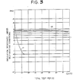
heating wire 2 of each sheathed heater was energized so that the surface temperature of themetal pipe 3 was maintained at a temperature of 950°C to determine the variation of the insulation resistance under self-heating conditions. It will be noted that when the insulation resistance under self-heating conditions was measured, the surface temperature was lowered down to 750°C. - The results of the life test and the insulation resistance values after 11 days in the test are shown in Table 7. The variation of the insulation resistance under self-heating conditions determined by the insulation resistance test is shown in Figure 5.
- In Figure 5, curves 65 and 11 correspond to the
sample 65 of the invention and thesample 11 of the prior art embodiment, respectively.
- As will be apparent from the results of Table 7 and Figure 5, the
sample 65 of the present invention had at least about 10 times the life of the knownsample 11 and exhibited a higher value of the insulation resistance under self-heating conditions as measured 11 days after the continuous test. - Thus, the effect attained by the addition of the nickel oxide powder was kept as it is.
- In this example, the electrofused magnesia powder was used as the electrically insulating powder but a similar tendency was shown when using, instead of the magnesia powder, electrofused alumina and silica powders.
- As will be appreciated from the above example, according to the method of fabricating a sheathed resistance heater of the invention, the nickel oxide powder is produced by roasting nickel sulfate and is admixed with the main component to give an electrically insulating powder useful in the present invention. As a consequence, there can be provided a sheathed resistance heater which has a long life and a high insulation resistance under self-heating conditions even after having been used over a long time.
- A metallic nickel powder (average size 3p-7p) was roasted to 900°C for 2 hours and reduced into pieces having a size below 1 11 to give a nickel oxide powder.
- An electrofused magnesia powder used as a main component of the electrically insulating
powder 4 was admixed with 1 wt% of the nickel oxide powder to obtain a mixed powder. This mixed powder was provided as electrically insulatingpowder 4. The electrofused magnesia powder, the heating wire and the metal pipe were same as used in Example 2. - The
heating wire 2 connected with the terminal bars at opposite ends thereof was inserted into themetal pipe 3, which was then filled up with the electrically insulatingpowder 4 which had been previously prepared. The pipe was subsequently subjected to the steps of rolling for reducing its diameter and annealing (1050°C, 10 minutes) to make a pipe of 500 mm in length and 6.6 mm in outer diameter. Themetal pipe 3 was tightly sealed at opposite ends thereof with alow melting glass 5 and a heat-resistant resin 6 to accomplish a sheathed resistance heater of sample No. 66. - For comparison purposes, there were fabricated known sheathed resistance heaters of sample No. 11 in which the electrofused magnesia powder alone was used as the electrically insulating powder and of sample No. 67 in which the electrofused magnesia powder admixed with 1 wt% of a commercially available nickel oxide powder was used as the electrically insulating
powder 4. - The finished sheathed heaters were each subjected to the measurement of an insulation resistance at a pipe surface temperature of 750°C immediately after the fabrication, and also to the life and insulation resistance tests described in below.
- The heating wire of each of the sheathed heaters was energized so that the surface temperature of the
metal pipe 3 was maintained at 950°C to check the number of days before disconnection of the wire. - The
heating wire 2 of each of the sheathed heaters was energized so that the surface temperature of themetal pipe 3 was maintained at 950°C to determine the variation of the insulation resistance under self-heating conditions. It will be noted that the measurement of the insulation resistance was effected after lowering the surface temperature of themetal pipe 3 down to 750°C. - In Table 8, there are shown the results of the insulation resistance under self-heating conditions measured immediately after the fabrication, and the life test and the insulation resistance under self-heating conditions measured after 11 days in the insulation resistance test. Moreover, the variation of the insulation resistance observed during the insulation resistance test is shown in Figure 6. In Figure 6, curves 66, 11 and 67 correspond to the inventive sheathed
heater 66, and the knownheaters 
- As will become apparent from the results of Table 8 and Figure 6, the known
sample 67 in which the commercially available nickel oxide powder was used considerably lowers in the insulation resistance as compared with the knownsample 11 in which the electrofused magnesia powder alone was used. With the embodiment of the invention in which the nickel oxide powder prepared according to the invention was used, its insulation resistance is smaller than that of the knownsample 11 but is much higher than that of the knownsample 67. Thus, the present invention is very effective. - The nickel oxide powder of the invention gives a great effect: the life is at least about ten times longer than the life of the known
sample 11 with the insulation resistance under self-heating conditions measured 11 days after the continuous test being also higher. - In this example, the electrofused magnesia powder was used as a main component of the electrically insulating powder but a similar tendency is shown when using, instead of the electrofused magnesia powder, electrofused alumina and silica powders.
- The method of fabricating a sheathed resistance heater according to the invention is a method in which there is used an electrically insulating powder to which is added a nickel oxide powder produced by roasting metallic nickel powder. By this, there can be provided a sheathed resistance heater which has a long life and a high insulation resistance under self-heating conditions after long-term use.
- A metallic nickel powder (
average particle 3 microns-7 microns) was roasted at 900°C for 2 hours and reduced to pieces to obtain nickel oxide particles. - The nickel oxide particles were classified into three groups including a group of particles having a size over 10 microns, a group of particles having a size ranging from 10 microns-5 microns, and a group of particles having a size below 5 microns.
- Thereafter, the particles were granulated to a level of 250 microns using water as a binder to give nickel oxide granules.
- An electrofused magnesia powder was provided as a main component and admixed with 1 wt% of the nickel oxide granules prepared by the above method to give a sample electrically insulating
powder 4. - The electrofused magnesia powder, heating wire and metal pipe used in this example were same as those used in Example 2.
- Into the
metal pipe 3 was inserted theheating wire 2 connected with theterminal bars 1 at opposite ends thereof. The pipe was filled up with the electrically insulatingpowder 4, followed by the steps of rolling for reducing the diameter and annealing (1050°C, 10 minutes), with the result that it has a length of 500 mm and an outer diameter of 6.6 mm. The resultingpipe 3 was tightly sealed at opposite ends thereof with alow melting glass 5 and a heat-resistant resin 6 to accomplish a sheathed resistance heater of sample No. 68. - A metallic nickel powder (
average size 3 microns-7 microns) was roasted at 900°C for 2 hours and ground to a level of below 5 microns, after which the powder was granulated by the use of water as a binder to provide nickel oxide granules. The granulation was effected so that the size was classified into groups of 420 microns-350 microns, 350 microns-297 microns, 297 microns-250 microns, 250 microns-177 microns, 177 microns-105 microns and below 105 microns. - Thereafter, Example 5 was repeated thereby obtaining sheathed resistance heaters numbered as 69.
- Nickel sulfate was crystallized from a nickel sulfate solution, after which the nickel sulfate crystals were roasted at 1000°C for 2 hours, followed by grinding to a level of below 5 microns. The powder was granulated using water as a binder to obtain particles having a size below 250 microns thereby providing a sample of nickel oxide granules.
- Subsequently, the general procedure of Example 5 was repeated to accomplish a sheathed resistance heater of sample No. 70.
- For comparison purposes, there were made prior art sheathed resistance heaters including a heater making use of an electrofused magnesia powder as the electrically insulating powder 4 (sample No. 11) and a heater of sample No. 71 in which the an electrically insulating powder used was in admixture with 1 wt% of a commercially available nickel oxide powder which was produced from a starting metallic nickel powder. In addition, a sheathed resistance heater of sample No. 72 was fabricated in which there was used an electrofused magnesia powder admixed with 1 wt% of a commercially available nickel oxide produced from starting nickel sulfate.
- The sheathed resistance heaters fabricated in Examples 5-7 and the prior-art heaters were classified, as shown in Table 9, according to the size of the primary particles of the added nickel oxide particles and the size of the granulated particles.
- The respective sheathed resistance heaters were subjected to the measurement of an initial insulation resistance at room temperature immediately after their fabrication, insulation resistance at a temperature on the pipe surface of 750°C, and dielectric strength at room temperature. Sheathed heaters which had an insulation resistance under self-heating conditions of below 1 mega ohms and a dielectric strength of below 1000 V were determined as a defective and fraction defectives in the respective groups were calculated. The results are shown in Table 9.

- Among the sample Nos. 68-72, the sheathed heaters of Groups C, G, H, I, J and K whose fraction defectives are below 1% were further subjected to the life test and the insulation resistance test under self-heating conditions.
- The
heating wire 2 of each heater was energized so that the surface temperature of themetal pipe 3 was maintained at 950°C to determine the number of days prior to disconnection of thewire 2. - The
heating wire 2 was energized so that the surface temperature of themetal pipe 3 was maintained at 950°C to determine a variation of insulation resistance. It will be noted that the measurement of the insulation resistance was effected after lowering the surface temperature of themetal pipe 3 down to 750°C. - The results of the life test and the insulation resistance test after 11 days are shown in Table 10.

- As will be apparent from Table 9, samples L and M in which the commercially available nickel oxide powders were used are much higher in fraction defective than sample K making use of the magnesia powder alone as the electrically insulating
powder 4 but the size of the nickel oxide particles is below 5 microns. Samples C, G, H, I and J of Examples 5-7 in which the nickel oxide particles granulated to have sizes below 250 microns show almost the same level of fraction defective as sample K. - However, when particles or granulated particles of sizes larger than 250 microns are used, they are poor in dispersibility upon mixing with the magnesia powder. As a result, such nickel oxide particles may be present as larger-size particles, or may segregate in some portions of sheathed heater such as by vibrations occurring upon filling of the particles. These phenomena will cause very high fraction defectives with regard to the insulation resistance and particularly the dielectric strength, presenting serious problems in the fabrication of the heaters.
- On the other hand, samples C, G, H, I and J and the prior-art sample K which were low in fraction defective as particularly shown in Table 9 were subjected to the life and insulation resistance tests to compare the characteristics of these heaters with one another. As will be apparent from Table 10, the life was about 10 times as long as that of the heater K using the known magnesia powder alone and the insulation resistance values under self-heating conditions measured 11 days after commencement of the test were kept at high levels.
- In Examples 5-7, the electrofused magnesia powder was used as a main component of the electrically insulating powder. In this connection, a similar tendency was found to be shown when using electrofused alumina and silica powders instead of the electrofused magnesia powder.
- As will be appreciated from the above description, the method of fabricating a sheathed resistance heater according to the invention is a method which comprises granulating nickel oxide particles ground to a level below 5 microns into granules having a size below 250 microns and adding the granules to an electrically insulating powder, with the result that there is stably provided a heater which has a long life and a high insulation resistance value under self-heating conditions after having been used over a long term.
Claims (2)
Priority Applications (1)
| Application Number | Priority Date | Filing Date | Title |
|---|---|---|---|
| AT82901434T ATE36797T1 (en) | 1981-05-18 | 1982-05-17 | SHIELDED HEATING ELEMENT AND ITS MANUFACTURING PROCESS. |
Applications Claiming Priority (12)
| Application Number | Priority Date | Filing Date | Title |
|---|---|---|---|
| JP75203/81 | 1981-05-18 | ||
| JP7520681A JPS57189484A (en) | 1981-05-18 | 1981-05-18 | Method of producing sheathed heater |
| JP7520381A JPS57189481A (en) | 1981-05-18 | 1981-05-18 | Sheathed heater |
| JP7520481A JPS57189482A (en) | 1981-05-18 | 1981-05-18 | Sheathed heater |
| JP75204/81 | 1981-05-18 | ||
| JP75206/81 | 1981-05-18 | ||
| JP76235/81 | 1981-05-19 | ||
| JP76208/81 | 1981-05-19 | ||
| JP7623581A JPS57191985A (en) | 1981-05-19 | 1981-05-19 | Method of producing sheathed heater |
| JP56076208A JPS57191980A (en) | 1981-05-19 | 1981-05-19 | Method of producing sheathed heater |
| JP7718281A JPS57191987A (en) | 1981-05-20 | 1981-05-20 | Sheathed heater |
| JP77182/81 | 1981-05-20 |
Publications (3)
| Publication Number | Publication Date |
|---|---|
| EP0079385A1 EP0079385A1 (en) | 1983-05-25 |
| EP0079385A4 EP0079385A4 (en) | 1983-09-20 |
| EP0079385B1 true EP0079385B1 (en) | 1988-08-24 |
Family
ID=27551322
Family Applications (1)
| Application Number | Title | Priority Date | Filing Date |
|---|---|---|---|
| EP82901434A Expired EP0079385B1 (en) | 1981-05-18 | 1982-05-17 | A shielded heating element and a method of manufacturing the same |
Country Status (5)
| Country | Link |
|---|---|
| US (1) | US4586020A (en) |
| EP (1) | EP0079385B1 (en) |
| AU (1) | AU541582B2 (en) |
| DE (1) | DE3278966D1 (en) |
| WO (1) | WO1982004171A1 (en) |
Families Citing this family (7)
| Publication number | Priority date | Publication date | Assignee | Title |
|---|---|---|---|---|
| US4900897A (en) * | 1988-11-21 | 1990-02-13 | Emerson Electric Co. | Sheathed electric heating element assembly |
| US5066852A (en) * | 1990-09-17 | 1991-11-19 | Teledyne Ind. Inc. | Thermoplastic end seal for electric heating elements |
| JP4076162B2 (en) | 2001-10-23 | 2008-04-16 | ローベルト ボツシユ ゲゼルシヤフト ミツト ベシユレンクテル ハフツング | Electrically heatable glow plug and method of making the electrically heatable glow plug |
| GB2494103B (en) * | 2011-08-01 | 2014-01-01 | Weston Aerospace Ltd | A Resistor and a Method of Manufacturing a Resistor Capable of Operating at High Temperatures |
| TW201325762A (en) * | 2011-12-20 | 2013-07-01 | Shu-Lian Chen | Manufacturing method of wave-shaped electric heating structure |
| WO2014061069A1 (en) * | 2012-10-19 | 2014-04-24 | 株式会社岡崎製作所 | Cryogenic temperature measurement resistor element |
| US10718527B2 (en) * | 2016-01-06 | 2020-07-21 | James William Masten, JR. | Infrared radiant emitter |
Family Cites Families (14)
| Publication number | Priority date | Publication date | Assignee | Title |
|---|---|---|---|---|
| US2280516A (en) * | 1942-04-21 | Method op treating magnesia and electrical insulating | ||
| US2280515A (en) * | 1942-04-21 | Electrical insulating material and method of producing the same | ||
| GB852693A (en) * | 1956-12-13 | 1960-10-26 | Perkin Elmer Corp | Electrically heated infra-red radiant energy source |
| SE327767B (en) * | 1964-02-07 | 1970-08-31 | Kanthal Ab | |
| DE1565279C3 (en) * | 1965-10-27 | 1973-09-20 | Bulten-Kanthal Ab, Hallstahammar (Schweden) | Sealed metal pipe element that works in air above 750 degrees C pipe temperature |
| GB1101275A (en) * | 1965-11-01 | 1968-01-31 | Kanthal Ab | Improvements in or relating to sealed tubular electric heating elements |
| US3477058A (en) * | 1968-02-01 | 1969-11-04 | Gen Electric | Magnesia insulated heating elements and methods of production |
| US3622755A (en) * | 1969-03-21 | 1971-11-23 | Gen Electric | Tubular heating elements and magnesia insulation therefor and method of production |
| DE1921789C3 (en) * | 1969-04-29 | 1975-02-20 | Dynamit Nobel Ag, 5210 Troisdorf | Process for the production of pipe fillings for electric radiators |
| JPS526956B2 (en) * | 1973-09-21 | 1977-02-25 | ||
| JPS6019120B2 (en) * | 1978-05-19 | 1985-05-14 | 松下電器産業株式会社 | Sea heater |
| JPS6030076B2 (en) * | 1978-12-28 | 1985-07-13 | 松下電器産業株式会社 | Sheathed heater and its manufacturing method |
| US4280932A (en) * | 1979-02-12 | 1981-07-28 | General Electric Company | Magnesia insulated heating elements |
| US4506251A (en) * | 1981-05-19 | 1985-03-19 | Matsushita Electric Industrial Co., Ltd. | Sheathed resistance heater |
-
1982
- 1982-05-17 EP EP82901434A patent/EP0079385B1/en not_active Expired
- 1982-05-17 WO PCT/JP1982/000171 patent/WO1982004171A1/en active IP Right Grant
- 1982-05-17 US US06/460,242 patent/US4586020A/en not_active Expired - Lifetime
- 1982-05-17 DE DE8282901434T patent/DE3278966D1/en not_active Expired
- 1982-05-17 AU AU83963/82A patent/AU541582B2/en not_active Ceased
Also Published As
| Publication number | Publication date |
|---|---|
| AU541582B2 (en) | 1985-01-10 |
| US4586020A (en) | 1986-04-29 |
| WO1982004171A1 (en) | 1982-11-25 |
| EP0079385A4 (en) | 1983-09-20 |
| DE3278966D1 (en) | 1988-09-29 |
| EP0079385A1 (en) | 1983-05-25 |
| AU8396382A (en) | 1982-12-07 |
Similar Documents
| Publication | Publication Date | Title |
|---|---|---|
| EP0079385B1 (en) | A shielded heating element and a method of manufacturing the same | |
| EP0316015A2 (en) | Material for resistor body and non-linear resistor made thereof | |
| EP0079386B1 (en) | A shielded heating element | |
| US4280932A (en) | Magnesia insulated heating elements | |
| US4234786A (en) | Magnesia insulated heating elements and method of making the same | |
| JPH0218560B2 (en) | ||
| JPS6362077B2 (en) | ||
| JPH0119636B2 (en) | ||
| JPH0138360B2 (en) | ||
| JPH0155554B2 (en) | ||
| JPS6143841B2 (en) | ||
| JPH01290549A (en) | Oxide semiconductor composition for thermistor | |
| US5075666A (en) | Varistor composition for high energy absorption | |
| JPS6362075B2 (en) | ||
| JPH0159711B2 (en) | ||
| JPS6362076B2 (en) | ||
| JPH0155555B2 (en) | ||
| JPS60115189A (en) | Method of producing sheathed heater | |
| JP3213647B2 (en) | Negative thermistor composition and negative thermistor | |
| JPS6041809B2 (en) | sheathed heater | |
| JPH0235436B2 (en) | ||
| JPS5914289A (en) | Sheathed heater | |
| JPS6322035B2 (en) | ||
| JPS647470B2 (en) | ||
| JPH0259462A (en) | Composition for thermistor |
Legal Events
| Date | Code | Title | Description |
|---|---|---|---|
| PUAI | Public reference made under article 153(3) epc to a published international application that has entered the european phase |
Free format text: ORIGINAL CODE: 0009012 |
|
| 17P | Request for examination filed |
Effective date: 19830118 |
|
| AK | Designated contracting states |
Designated state(s): AT DE FR GB SE |
|
| GRAA | (expected) grant |
Free format text: ORIGINAL CODE: 0009210 |
|
| AK | Designated contracting states |
Kind code of ref document: B1 Designated state(s): AT DE FR GB SE |
|
| REF | Corresponds to: |
Ref document number: 36797 Country of ref document: AT Date of ref document: 19880915 Kind code of ref document: T |
|
| REF | Corresponds to: |
Ref document number: 3278966 Country of ref document: DE Date of ref document: 19880929 |
|
| ET | Fr: translation filed | ||
| PLBE | No opposition filed within time limit |
Free format text: ORIGINAL CODE: 0009261 |
|
| STAA | Information on the status of an ep patent application or granted ep patent |
Free format text: STATUS: NO OPPOSITION FILED WITHIN TIME LIMIT |
|
| 26N | No opposition filed | ||
| EAL | Se: european patent in force in sweden |
Ref document number: 82901434.9 |
|
| PGFP | Annual fee paid to national office [announced via postgrant information from national office to epo] |
Ref country code: GB Payment date: 19950510 Year of fee payment: 14 Ref country code: FR Payment date: 19950510 Year of fee payment: 14 |
|
| PGFP | Annual fee paid to national office [announced via postgrant information from national office to epo] |
Ref country code: DE Payment date: 19950511 Year of fee payment: 14 |
|
| PGFP | Annual fee paid to national office [announced via postgrant information from national office to epo] |
Ref country code: SE Payment date: 19950517 Year of fee payment: 14 |
|
| PG25 | Lapsed in a contracting state [announced via postgrant information from national office to epo] |
Ref country code: GB Effective date: 19960517 |
|
| PG25 | Lapsed in a contracting state [announced via postgrant information from national office to epo] |
Ref country code: SE Effective date: 19960518 |
|
| GBPC | Gb: european patent ceased through non-payment of renewal fee |
Effective date: 19960517 |
|
| PG25 | Lapsed in a contracting state [announced via postgrant information from national office to epo] |
Ref country code: FR Effective date: 19970131 |
|
| PG25 | Lapsed in a contracting state [announced via postgrant information from national office to epo] |
Ref country code: DE Effective date: 19970201 |
|
| EUG | Se: european patent has lapsed |
Ref document number: 82901434.9 |
|
| REG | Reference to a national code |
Ref country code: FR Ref legal event code: ST |
|
| PGFP | Annual fee paid to national office [announced via postgrant information from national office to epo] |
Ref country code: AT Payment date: 19980514 Year of fee payment: 17 |
|
| PG25 | Lapsed in a contracting state [announced via postgrant information from national office to epo] |
Ref country code: AT Free format text: LAPSE BECAUSE OF NON-PAYMENT OF DUE FEES Effective date: 19990517 |