EP0078417B1 - D.c. series motor for vehicles - Google Patents
D.c. series motor for vehicles Download PDFInfo
- Publication number
- EP0078417B1 EP0078417B1 EP82109429A EP82109429A EP0078417B1 EP 0078417 B1 EP0078417 B1 EP 0078417B1 EP 82109429 A EP82109429 A EP 82109429A EP 82109429 A EP82109429 A EP 82109429A EP 0078417 B1 EP0078417 B1 EP 0078417B1
- Authority
- EP
- European Patent Office
- Prior art keywords
- main pole
- motor
- series
- winding
- pole winding
- Prior art date
- Legal status (The legal status is an assumption and is not a legal conclusion. Google has not performed a legal analysis and makes no representation as to the accuracy of the status listed.)
- Expired
Links
Images
Classifications
-
- H—ELECTRICITY
- H02—GENERATION; CONVERSION OR DISTRIBUTION OF ELECTRIC POWER
- H02K—DYNAMO-ELECTRIC MACHINES
- H02K23/00—DC commutator motors or generators having mechanical commutator; Universal AC/DC commutator motors
- H02K23/02—DC commutator motors or generators having mechanical commutator; Universal AC/DC commutator motors characterised by arrangement for exciting
- H02K23/08—DC commutator motors or generators having mechanical commutator; Universal AC/DC commutator motors characterised by arrangement for exciting having series connection of excitation windings
-
- B—PERFORMING OPERATIONS; TRANSPORTING
- B60—VEHICLES IN GENERAL
- B60L—PROPULSION OF ELECTRICALLY-PROPELLED VEHICLES; SUPPLYING ELECTRIC POWER FOR AUXILIARY EQUIPMENT OF ELECTRICALLY-PROPELLED VEHICLES; ELECTRODYNAMIC BRAKE SYSTEMS FOR VEHICLES IN GENERAL; MAGNETIC SUSPENSION OR LEVITATION FOR VEHICLES; MONITORING OPERATING VARIABLES OF ELECTRICALLY-PROPELLED VEHICLES; ELECTRIC SAFETY DEVICES FOR ELECTRICALLY-PROPELLED VEHICLES
- B60L9/00—Electric propulsion with power supply external to the vehicle
- B60L9/02—Electric propulsion with power supply external to the vehicle using dc motors
- B60L9/08—Electric propulsion with power supply external to the vehicle using dc motors fed from ac supply lines
- B60L9/12—Electric propulsion with power supply external to the vehicle using dc motors fed from ac supply lines with static converters
-
- B—PERFORMING OPERATIONS; TRANSPORTING
- B60—VEHICLES IN GENERAL
- B60L—PROPULSION OF ELECTRICALLY-PROPELLED VEHICLES; SUPPLYING ELECTRIC POWER FOR AUXILIARY EQUIPMENT OF ELECTRICALLY-PROPELLED VEHICLES; ELECTRODYNAMIC BRAKE SYSTEMS FOR VEHICLES IN GENERAL; MAGNETIC SUSPENSION OR LEVITATION FOR VEHICLES; MONITORING OPERATING VARIABLES OF ELECTRICALLY-PROPELLED VEHICLES; ELECTRIC SAFETY DEVICES FOR ELECTRICALLY-PROPELLED VEHICLES
- B60L2200/00—Type of vehicles
- B60L2200/26—Rail vehicles
Definitions
- the present invention relates to a D.C. series motor for vehicles according to the preamble of Claim 1 suitable for a pulsating current operation.
- DE-C-276 990 discloses a D.C. series motor for vehicles according to the preamble of Claim 1.
- Such a D.C. motor used for railroad vehicles is driven not only by a D.C. current but also by a pulsating unidirectional current.
- the D.C. motor is supplied with power through a pantagraph from a power supply source of different types and qualities, i.e. a single-phase A.C. source or a three-phase A.C. source, and the other reason is that a reactor of a filtering device for supplying power to the D.C. motor installed on a railroad vehicle is limited in its physical dimension and hence the rectification efficiency of the filtering device is lowered.
- the D.C. motor for a railroad vehicle is not always supplied with a complete D.C. current, which results in driving of the D.C. motor by the pulsating motor including an A.C. component.
- the D.C. series motor according to the DE-C-276 990 which is driven by a pulsating unidirectional current applied thereto, includes an armature, a main pole winding and a resistive shunt connected in parallel with said main pole winding for bypassing the pulsating unidirectional current flowing through said main pole winding.
- An interpole winding connected in series with the armature and in series with the main pole winding which is mentioned in the preamble of Claim 1 is a feature for D.C. series motor which is commonly known and i.e. is disclosed in DE-C-674 671.
- a sparking voltage E s is generated due to a vector difference between a reactance voltage E r of the motor (a voltage between brushes of the D.C. motor) and a velocity e.m.f. E,, generated by interpole magnetic fluxes.
- Means for compensating resultant sparking voltage E s p (3V) of the arc voltage E s and a transformer e.m.f. E t of a main pole has not been proposed.
- a commutation performance of the pulsating current driven motor for the rolling stocks has been low due to the resultant sparking voltage E s p.
- the object is solved by the features in the characterizing part of the Claim 1.
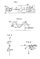
- Figure 1 shows an armature circuit of a pulsating current driven D.C. motor to which the present invention is applicable.
- a single phase A.C. power supply is supplied to a transformer 2 from a stringing through a pantagraph 1, and an output from the transformer 2 is supplied to a main motor 20 through a rectifier (e.g. a diode bridge rectifier) 3 and a filtering reactor 4.
- a main pole 7 has a pure resistor 8 connected in parallel thereto to minimize a pulsating current component flowing through the main pole 7 so that a field current is shunted by the pure resistor 8.
- An inductive shunt 9 and a field-weakening resistor 10 are selectively inserted by a switch 11 to effect a field-weakening control (high speed control).
- the inductive shunt 9 not only contributes to the field-weakening control but also contributes to improve a rectification performance in the pulsating current driven D.C. motor.
- Figure 2 shows current waveforms of currents flowing through an armature 5 and an interpole 6.
- a pulsating factor ⁇ is generally expressed by The pulsating factor is 50%-25% at most in a present technology.
- an eddy current flows through a magnetic circuit of the interpole because it includes a portion not. completely laminated such as a magnetic frame so that an interpole magnetic flux ⁇ is retarded by ⁇ i with respect to a current I and an amplitude thereof is reduced as shown in Figure 2. Accordingly, the commutation performance is lowered than when the motor is D.C. driven.
- Figure 3 illustrates a relation thereof.
- the commutation performance is high because a reactance voltage E r and a velocity e.m.f. E ⁇ DC generated by the interpole magnetic flux are equal.
- the velocity e.m.f. E ⁇ DC is changed to E ⁇ by the eddy current and a phase thereof is shifted by ⁇ i relative to the reactance voltage E r and an amplitude thereof is reduced.
- the reactance voltage E r and the velocity e.m.f. E ⁇ generated by the interpole magnetic flux in the pulsating current operation do not cancel each other and a sparking voltage E s remains. This is one of the factors which lower the commutation performance in the pulsating current operation.
- transformer e.m.f. of the main pole Another factor to lower the rectification performance is the transformer e.m.f. of the main pole. This is described below.
- Figure 4 shows a vector diagram illustrating a relation among the reactance voltage E r , the velocity e.m.f. E ⁇ DC and the sparking voltage E s when the transformer e.m.f. E t is taken into consideration. Since the main pole 7 has the field shunting resistor 8 to reduce the pulsating current component, the pulsating current component in the main pole 7 is smaller than the pulsating current component in the interpole 6 and the armature 5 and a phase thereof is retarded by y. A phase of the transformer e.m.f. E t is retarded by ( ⁇ + ⁇ f ⁇ 90°) relative to the velocity e.m.f.
- the reactance voltage E r , the velocity e.m.f. E ⁇ by the interpole magnetic flux and the sparking voltage E s are constant for a given motor and cannot be changed.
- the magnitude and the phase of the transformer e.m.f. E t can be changed by appropriately selecting the inductance of the inductive shunt.
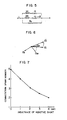
- Figure 5 shows an equivalent circuit of the main pole under the field-weaking control.
- the current if in the main pole is given by where i is a current in the interpole and the armature, X, is the inductance of the inductive shunt, r i is the field-weaking resistance, X f and r f are an inductive component and a resistive component of the main pole winding and R s is a field shunt resistance.
- Figure 6 shows a vector diagram of the sparking voltage E s , the transformer e.m.f. E t and the resultant sparking voltage E s p when X, is increased in the formula (2). As seen from Figure 6, as the magnitude and the phase of the transformer e.m.f. E t are increased, the magnitude of the resultant sparking voltage E sp -is reduced so that the commutation performance is improved.
- Figure 7 shows a relation between the inductance of the inductive shunt and the rectification spark numbers (resultant sparking voltage E s p) measured under the field-weakening control of the vehicle motor.
- the spark numbers include 1 to 5, in which 1 indicates a non-sparking condition and 5 indicates a highest sparking condition.
- the inductance of the inductive shunt is increased, the commutation performance is remarkably improved.
- the inductance of larger than 2 mH is sufficient.
- the inductance of the main pole under this condition is approximately 10 mH.
- the inductive shunt having the inductance which is at least 20% of the inductance of the main pole winding is connected in parallel with the main pole winding. Accordingly, the vehicle motor having an improved commutation performance in the pulsating current operation is provided.
Landscapes
- Engineering & Computer Science (AREA)
- Power Engineering (AREA)
- Life Sciences & Earth Sciences (AREA)
- Sustainable Development (AREA)
- Sustainable Energy (AREA)
- Transportation (AREA)
- Mechanical Engineering (AREA)
- Control Of Direct Current Motors (AREA)
- Dc Machiner (AREA)
Description
- The present invention relates to a D.C. series motor for vehicles according to the preamble of Claim 1 suitable for a pulsating current operation.
- The document DE-C-276 990 discloses a D.C. series motor for vehicles according to the preamble of Claim 1.
- Such a D.C. motor used for railroad vehicles is driven not only by a D.C. current but also by a pulsating unidirectional current. Particularly, one of the reasons why the D.C. motor for railroad vehicles is driven by the pulsating current is that the D.C. motor is supplied with power through a pantagraph from a power supply source of different types and qualities, i.e. a single-phase A.C. source or a three-phase A.C. source, and the other reason is that a reactor of a filtering device for supplying power to the D.C. motor installed on a railroad vehicle is limited in its physical dimension and hence the rectification efficiency of the filtering device is lowered. From the reasons mentioned above, the D.C. motor for a railroad vehicle is not always supplied with a complete D.C. current, which results in driving of the D.C. motor by the pulsating motor including an A.C. component.
- The D.C. series motor according to the DE-C-276 990, which is driven by a pulsating unidirectional current applied thereto, includes an armature, a main pole winding and a resistive shunt connected in parallel with said main pole winding for bypassing the pulsating unidirectional current flowing through said main pole winding.
- An interpole winding connected in series with the armature and in series with the main pole winding which is mentioned in the preamble of Claim 1 is a feature for D.C. series motor which is commonly known and i.e. is disclosed in DE-C-674 671.
- In a D.C. series motor known from DE-C-546 466, when it is operated by the pulsating current, a sparking voltage Es is generated due to a vector difference between a reactance voltage Er of the motor (a voltage between brushes of the D.C. motor) and a velocity e.m.f. E,, generated by interpole magnetic fluxes. Means for compensating resultant sparking voltage Esp (3V) of the arc voltage Es and a transformer e.m.f. Et of a main pole has not been proposed. As a result, a commutation performance of the pulsating current driven motor for the rolling stocks has been low due to the resultant sparking voltage Esp.
- It is an object of the present invention to provide a D.C. motor for a vehicle operated by a pulsating current with a reduced resultant sparking voltage in order to improve a commutation performance in the pulsating current operation. The object is solved by the features in the characterizing part of the Claim 1.
- The
subclaims - Other objects, features and advantages of the present invention will be apparent from the following detailed description of the invention with reference to the accompanying drawings, in which:
- Figure 1 shows a circuit configuration of a pulsating current motor to which the present invention is applicable;
- Figure 2 shows a waveform illustrating a phase relationship between an armature current and an interpole magnetic flux of the pulsating current motor shown in Figure 1;
- Figure 3 shows a vector diagram illustrating a relation among a reactance voltage, a velocity e.m.f. by the interpole magnetic flux and a sparking voltage of the pulsating current motor;
- Figure 4 shows a vector diagram illustrating a relation among the reactance voltage, the velocity e.m.f. and the sparking voltage when a transformer e.m.f. is taken into consideration;
- Figure 5 shows an equivalent circuit of a main pole under a field-weakening control;
- Figure 6 shows a vector diagram illustrating a relation among the arc voltage, the transformer e.m.f. and a resultant sparking voltage when an inductance of an inductive shunt is varied; and
- Figure 7 shows a relation between the inductance of the inductive shunt and the commutation spark numbers measured under the field-weakening control of the vehicle motor.
- One embodiment of the present invention is now explained with reference to the drawings.
- Figure 1 shows an armature circuit of a pulsating current driven D.C. motor to which the present invention is applicable. A single phase A.C. power supply is supplied to a
transformer 2 from a stringing through a pantagraph 1, and an output from thetransformer 2 is supplied to amain motor 20 through a rectifier (e.g. a diode bridge rectifier) 3 and afiltering reactor 4. A main pole 7 has apure resistor 8 connected in parallel thereto to minimize a pulsating current component flowing through the main pole 7 so that a field current is shunted by thepure resistor 8. - An inductive shunt 9 and a field-weakening resistor 10 are selectively inserted by a switch 11 to effect a field-weakening control (high speed control). The inductive shunt 9 not only contributes to the field-weakening control but also contributes to improve a rectification performance in the pulsating current driven D.C. motor.
- Figure 2 shows current waveforms of currents flowing through an
armature 5 and an interpole 6. A pulsating factor µ is generally expressed by
- Figure 3 illustrates a relation thereof. When the vehicle motor is D.C. driven, the commutation performance is high because a reactance voltage Er and a velocity e.m.f. EΦDC generated by the interpole magnetic flux are equal. However, when the rolling stocks motor is pulsating current driven, the velocity e.m.f. EΦDC is changed to EΦ by the eddy current and a phase thereof is shifted by βi relative to the reactance voltage Er and an amplitude thereof is reduced. As a result, the reactance voltage Er and the velocity e.m.f. EΦ generated by the interpole magnetic flux in the pulsating current operation do not cancel each other and a sparking voltage Es remains. This is one of the factors which lower the commutation performance in the pulsating current operation.
- Another factor to lower the rectification performance is the transformer e.m.f. of the main pole. This is described below.
- Figure 4 shows a vector diagram illustrating a relation among the reactance voltage Er, the velocity e.m.f. EΦDC and the sparking voltage Es when the transformer e.m.f. Et is taken into consideration. Since the main pole 7 has the
field shunting resistor 8 to reduce the pulsating current component, the pulsating current component in the main pole 7 is smaller than the pulsating current component in the interpole 6 and thearmature 5 and a phase thereof is retarded by y. A phase of the transformer e.m.f. Et is retarded by (γ+βf―90°) relative to the velocity e.m.f. EΦDC, where βf is a phase difference between the main pole magnetic flux and the main pole current. The commutation performance in the pulsating current operation is lowered because the resultant sparking voltage Esp of the transformer e.m.f. Et and the sparking voltage Es is not compensated. In Figure 4, If denotes the pulsating current component of the main pole current and Φf denotes the pulsating component of the main pole magnetic flux. - The commutation performance in the pulsating current operation is not seriously lowered to compare with the D.C. operation in a full field operation (low speed operation) but it is lowered in the field-weakening control (high speed operation). Therefore, only the field-weakening control is considered here.
- The reactance voltage Er, the velocity e.m.f. EΦ by the interpole magnetic flux and the sparking voltage Es are constant for a given motor and cannot be changed. On the other hand, the magnitude and the phase of the transformer e.m.f. Et can be changed by appropriately selecting the inductance of the inductive shunt.
- Figure 5 shows an equivalent circuit of the main pole under the field-weaking control. The current if in the main pole is given by

- Figure 7 shows a relation between the inductance of the inductive shunt and the rectification spark numbers (resultant sparking voltage Esp) measured under the field-weakening control of the vehicle motor. The spark numbers include 1 to 5, in which 1 indicates a non-sparking condition and 5 indicates a highest sparking condition. As seen from Figure 7, as the inductance of the inductive shunt is increased, the commutation performance is remarkably improved.
- Assuming that the practically acceptable spark numbers are 3 to 5, the inductance of larger than 2 mH is sufficient. The inductance of the main pole under this condition is approximately 10 mH. By providing the inductive shunt having the inductance which is at least 20% of the inductance of the main pole winding, the commutation performance in the pulsating current operation of the vehicle motor can be substantially improved.
- As described hereinabove, according to the present invention, the inductive shunt having the inductance which is at least 20% of the inductance of the main pole winding is connected in parallel with the main pole winding. Accordingly, the vehicle motor having an improved commutation performance in the pulsating current operation is provided.
Claims (3)
Applications Claiming Priority (2)
| Application Number | Priority Date | Filing Date | Title |
|---|---|---|---|
| JP162647/81 | 1981-10-14 | ||
| JP56162647A JPS5866566A (en) | 1981-10-14 | 1981-10-14 | Motor for vehicle |
Publications (2)
| Publication Number | Publication Date |
|---|---|
| EP0078417A1 EP0078417A1 (en) | 1983-05-11 |
| EP0078417B1 true EP0078417B1 (en) | 1987-04-01 |
Family
ID=15758591
Family Applications (1)
| Application Number | Title | Priority Date | Filing Date |
|---|---|---|---|
| EP82109429A Expired EP0078417B1 (en) | 1981-10-14 | 1982-10-12 | D.c. series motor for vehicles |
Country Status (4)
| Country | Link |
|---|---|
| EP (1) | EP0078417B1 (en) |
| JP (1) | JPS5866566A (en) |
| DE (1) | DE3275966D1 (en) |
| ZA (1) | ZA827491B (en) |
Families Citing this family (2)
| Publication number | Priority date | Publication date | Assignee | Title |
|---|---|---|---|---|
| DE4204626A1 (en) * | 1992-02-15 | 1993-08-19 | Pierburg Gmbh | UNIVERSAL ELECTRIC MOTOR |
| JP2001008424A (en) * | 1999-06-17 | 2001-01-12 | Matsushita Electric Ind Co Ltd | Dc commutator motor |
Family Cites Families (6)
| Publication number | Priority date | Publication date | Assignee | Title |
|---|---|---|---|---|
| DE276990C (en) * | ||||
| DE594373C (en) * | 1934-03-16 | Siemens Schuckertwerke Akt Ges | Commutation device for alternating current commutator motors fed with pulsating direct current | |
| DE596466C (en) * | 1932-11-29 | 1934-05-08 | Aeg | Circuit arrangement for motors that are fed by a rectifier |
| DE674671C (en) * | 1933-11-08 | 1939-04-19 | Siemens Schuckertwerke Akt Ges | Device for improving the commutation of direct current series motors fed by a single-phase rectifier |
| DE1157257B (en) * | 1960-10-25 | 1963-11-14 | Siemens Ag | Arrangement for driving the traction motors of electric traction vehicles, which are operated with undulating direct current |
| JPS4982915A (en) * | 1972-12-16 | 1974-08-09 |
-
1981
- 1981-10-14 JP JP56162647A patent/JPS5866566A/en active Granted
-
1982
- 1982-10-12 EP EP82109429A patent/EP0078417B1/en not_active Expired
- 1982-10-12 DE DE8282109429T patent/DE3275966D1/en not_active Expired
- 1982-10-13 ZA ZA827491A patent/ZA827491B/en unknown
Non-Patent Citations (2)
| Title |
|---|
| ANONYMOUS: "Elektrische Traktion", BULLETIN OERLIKON NR.392/393, January 1970 (1970-01-01), Zurich, pages 36 - 43, XP055281586 |
| KATSUHIRO KINOSHITA: "ED-77 A-C Electric Locomotive", TOSHIBA REVIEW, January 1968 (1968-01-01), pages 12 - 17, XP055281592 |
Also Published As
| Publication number | Publication date |
|---|---|
| ZA827491B (en) | 1983-08-31 |
| EP0078417A1 (en) | 1983-05-11 |
| JPS6332028B2 (en) | 1988-06-28 |
| DE3275966D1 (en) | 1987-05-07 |
| JPS5866566A (en) | 1983-04-20 |
Similar Documents
| Publication | Publication Date | Title |
|---|---|---|
| CA2110832C (en) | Inverter power supply for welding | |
| US5982136A (en) | Circuit for sensing current in power trains for motor control | |
| EP0534153B1 (en) | Charging generator for vehicle | |
| US3770976A (en) | System for increasing the output of a multi-phase rectified rotary field system | |
| WO2011080575A1 (en) | A multi-output engine welder supplying full electrical power capacity to a single welding output and method | |
| US3829652A (en) | Arc welder and combined auxiliary power unit and method of arc welding | |
| KR100426886B1 (en) | Voltage supply with two output voltages | |
| EP0078417B1 (en) | D.c. series motor for vehicles | |
| US3899652A (en) | Extended range inductor alternator arc welder | |
| JPS60219946A (en) | Self-excited generator | |
| JP4534218B2 (en) | Engine driven DC arc welding machine | |
| JP3181871B2 (en) | Separately driven inverter type spindle drive generator | |
| JPH0331497Y2 (en) | ||
| Byrne et al. | Compatible controller-motor system for battery-electric vehicle | |
| JPH0332303A (en) | Controller for dc series motor | |
| JPH062404Y2 (en) | Electric vehicle running control device | |
| EP0582416B1 (en) | Series wound electric motor with a rectified additional field excitation | |
| JPH0453124Y2 (en) | ||
| JPH09107697A (en) | Charging system for ac generator for vehicle | |
| JPH06233600A (en) | Field circuit of alternator | |
| SU1668173A1 (en) | Apparatus for protection from slippage of wheel pairs of diesel locomotive with power transmission of alternating constant current | |
| JPH0538114A (en) | Ac generator for vehicle | |
| SU1684878A1 (en) | Voltage converter | |
| JP2560004B2 (en) | DC motor controller | |
| JPS60245500A (en) | Variable speed rotary electric machine |
Legal Events
| Date | Code | Title | Description |
|---|---|---|---|
| PUAI | Public reference made under article 153(3) epc to a published international application that has entered the european phase |
Free format text: ORIGINAL CODE: 0009012 |
|
| AK | Designated contracting states |
Designated state(s): DE FR GB |
|
| 17P | Request for examination filed |
Effective date: 19830513 |
|
| GRAA | (expected) grant |
Free format text: ORIGINAL CODE: 0009210 |
|
| AK | Designated contracting states |
Kind code of ref document: B1 Designated state(s): DE FR GB |
|
| REF | Corresponds to: |
Ref document number: 3275966 Country of ref document: DE Date of ref document: 19870507 |
|
| ET | Fr: translation filed | ||
| PLBI | Opposition filed |
Free format text: ORIGINAL CODE: 0009260 |
|
| 26 | Opposition filed |
Opponent name: BBC BROWN BOVERI AG Effective date: 19871202 |
|
| PGFP | Annual fee paid to national office [announced via postgrant information from national office to epo] |
Ref country code: GB Payment date: 19900907 Year of fee payment: 9 |
|
| PGFP | Annual fee paid to national office [announced via postgrant information from national office to epo] |
Ref country code: DE Payment date: 19901106 Year of fee payment: 9 |
|
| RDAG | Patent revoked |
Free format text: ORIGINAL CODE: 0009271 |
|
| STAA | Information on the status of an ep patent application or granted ep patent |
Free format text: STATUS: PATENT REVOKED |
|
| 27W | Patent revoked |
Effective date: 19910225 |
|
| GBPR | Gb: patent revoked under art. 102 of the ep convention designating the uk as contracting state | ||
| PGFP | Annual fee paid to national office [announced via postgrant information from national office to epo] |
Ref country code: FR Payment date: 19910918 Year of fee payment: 10 |