EP0077050A1 - Holding device for annular cores provided with windings - Google Patents
Holding device for annular cores provided with windings Download PDFInfo
- Publication number
- EP0077050A1 EP0077050A1 EP82109344A EP82109344A EP0077050A1 EP 0077050 A1 EP0077050 A1 EP 0077050A1 EP 82109344 A EP82109344 A EP 82109344A EP 82109344 A EP82109344 A EP 82109344A EP 0077050 A1 EP0077050 A1 EP 0077050A1
- Authority
- EP
- European Patent Office
- Prior art keywords
- holding device
- carrier plate
- holding
- core
- toroidal
- Prior art date
- Legal status (The legal status is an assumption and is not a legal conclusion. Google has not performed a legal analysis and makes no representation as to the accuracy of the status listed.)
- Granted
Links
Images


Classifications
-
- H—ELECTRICITY
- H01—ELECTRIC ELEMENTS
- H01F—MAGNETS; INDUCTANCES; TRANSFORMERS; SELECTION OF MATERIALS FOR THEIR MAGNETIC PROPERTIES
- H01F27/00—Details of transformers or inductances, in general
- H01F27/06—Mounting, supporting or suspending transformers, reactors or choke coils not being of the signal type
-
- H—ELECTRICITY
- H01—ELECTRIC ELEMENTS
- H01F—MAGNETS; INDUCTANCES; TRANSFORMERS; SELECTION OF MATERIALS FOR THEIR MAGNETIC PROPERTIES
- H01F27/00—Details of transformers or inductances, in general
- H01F27/24—Magnetic cores
- H01F27/26—Fastening parts of the core together; Fastening or mounting the core on casing or support
- H01F27/266—Fastening or mounting the core on casing or support
Abstract
Description
Die vorliegende Erfindung bezieht sich auf eine Haltevorrichtung für mit Wicklungen versehene Ringkerne.The present invention relates to a holding device for toroidal cores provided with windings.
Mit Wicklungen versehene Ringkerne, wie beispielsweise Ringkerntransformatoren, Ringkerndrosseln oder sogar gelegentlich sogar einfache Potentiometer sind in Verbindung mit anderen Schaltkreiselementen nicht einfach zu befestigen, weil sie einerseits verhältnismäßig schwer sind und andererseits eine unmittelbare mechanische Befestigung nicht zulassen, da der an sich stabile Ringkern vollständig von einer Wicklung, ggf. in vielen Lagen, umgeben ist, so daß eine Halterung an der Wicklung angreifen müßte. Dabei muß der Ringkern sehr starr und absolut ortsfest zu anderen Bauelementen befestigt werden, da die Wicklungsenden mit anderen ortsfesten Teilen verbunden, im allgemeinen verlötet werden müssen und jede Relativbewegung zwischen diesen Teilen not- wendiger Weise zu Beschädigungen führen muß.Toroidal cores provided with windings, such as toroidal transformers, toroidal chokes or even occasionally even simple potentiometers, are not easy to attach in connection with other circuit elements because, on the one hand, they are relatively heavy and, on the other hand, do not permit direct mechanical attachment, since the toroid, which is stable per se, is completely devoid of one winding, g g f. in many layers, is surrounded, so that a bracket would have to attack the winding. The ring core has to be very rigid and absolutely stationary be attached to other components, because the winding ends with other stationary parts connected, have to be soldered in general, and must perform any relative movement between these parts emergency wendi g he way damage.
Es ist bekannt, Ringkerne in einem speziellen Gehäuse einzeln oder auch zusammen mit anderen Bauelementen bzw. weiteren mit Wicklungen versehenen Ringkernen örtlich zu fixieren und das Gehäuse in der Gesamtheit so zuvergießen, daß eine Einheit aus Ringkern und Gehäuse geschaffen wird, wobei dann die Anschlußfahnen für die Wicklungen an der Gehäusewand bzw. mit der Gehäusewand starr verbundenen Gehäuseteilen an den dort angebrachten Lötfahnen, Lötstiften usw. befestigt werden.It is known to fix ring cores locally in a special housing individually or together with other components or further ring cores provided with windings and to cast the housing in its entirety in such a way that a unit consisting of ring core and housing is created, the connecting lugs for the windings on the housing wall or housing parts rigidly connected to the housing wall are attached to the soldering lugs, soldering pins etc. attached there.
Für die Befestigung von mit Wicklungen versehenen Ringkernen auf Schaltungsteilen oder dgl., wo kein Gehäuse vorgesehen werden kann, wird der Ringkern im allgemeinen zwischen zwei mit einer elastischen Schicht zum Ringkern hin versehenen Platte eingespannt und die Platten bzw. der durch die Platten hindurchgeführte, gleichzeitig ein Verspannen der Platten'übernehmende Stift wird an dem entsprechenden Gerät bzw. den Schaltungsteilen befestigt. Diese Art der Befestigung ermöglicht zwar den Ringkern ortsfest an weiteren Schaltungsteilen, z.B. auf Leiterplatten oder dgl. zu be- .festigen. Mit Rücksicht auf das vorhandene Gewicht des Ringkernes selbst müssen dabei die Platten aber verhältnismäßig stark gegeneinander verspannt werden, was sich in einem entsprechend hohen Druck auf die Wicklung des Ringkernes selbst nachteilig auswirkt. Dabei kann es verhältnismäßig leicht zu Beschädigungen der Lackisolierung der einzelnen Windungen kommen. Insbesondere auch deshalb, weil die Halterung verhältnismäßig großen Temperaturschwankungen ausgesetzt ist.For the fastening of ring cores provided with windings on circuit parts or the like, where no housing can be provided, the ring core is generally clamped between two plates provided with an elastic layer towards the ring core and the plates or those passed through the plates simultaneously tensioning the plate-receiving pin is attached to the corresponding device or the circuit parts. This type of attachment allows the toroid to be fixed to other circuit parts, e.g. to be fixed on printed circuit boards or the like. In view of the existing weight of the toroid itself, the plates must be braced relatively strongly against each other, which has a disadvantageous effect on the winding of the toroid itself in a correspondingly high pressure. This can damage the paint insulation of the individual turns relatively easily. Especially because the holder is exposed to relatively large temperature fluctuations.
Aufgabe der Erfindung ist es, eine Haltevorrichtung für mit Wicklungen versehene Ringkerne anzugeben, die einfach im Aufbau ist, die die unmittelbare Befestigung der Ringkerne auf beliebigen Haltevorrichtungen, Schaltungsplatten usw. ermöglicht und die so ausgebildet ist, daß der Ringkern praktisch durckfrei gehalten wird.The object of the invention is to provide a holding device for toroidal cores provided with windings, which is simple in construction, the direct attachment of the toroidal cores on any holding devices, circuit plates etc. allows and which is designed so that the ring core is kept practically free of pressure.
Weiter soll die Haltevorrichtung zum unmittelbaren Anbringen von Anschlußstiften, Lötfahnen usw. geeignet sein, um eine Befestigung der Ringkerne auch auf gedruckten Leiterplatten oder dgl. (sog. Print-Befestigung) zu ermöglichen.Furthermore, the holding device should be suitable for the direct attachment of connecting pins, soldering lugs, etc., in order to enable the toroidal cores to also be attached to printed circuit boards or the like (so-called print attachment).
Die vorgenannte Aufgabe wird mit einer Haltevorrichtung mit den Merkmalen nach Patentanspruch 1 gelöst.The above object is achieved with a holding device with the features of claim 1.
Die Haltevorrichtung nach der Erfindung besteht demgemäß aus einer dem Durchmesser des bewickelten Ringkernes angepaßten Trägerplatte die mit einem Zentrierdorn, der den Innenraum des Ringkernes durchdringt, versehen ist, wobei der Ringkern selbst auf dieser Halteplatte mittels einer Vergußmasse gehalten ist.The holding device according to the invention accordingly consists of a support plate which is adapted to the diameter of the wound ring core and which is provided with a centering mandrel which penetrates the interior of the ring core, the ring core itself being held on this holding plate by means of a casting compound.
Die Lehre nach der Erfindung, die Trägerplatte dem Aussendurchmesser des bewickelten Ringkernes anzupassen, bedeutet zunächst, daß die Platte keinen kleineren Durchmesser haben soll, als der bewickelte Ringkern, um mechanische Beschädigungen an der Aussenseite der Wicklung zu vermeiden.The teaching according to the invention to adapt the carrier plate to the outer diameter of the wound toroid initially means that the plate should not have a smaller diameter than the wound toroid in order to avoid mechanical damage to the outside of the winding.
Sofern aber gemäß einer vorteilhaften Weiterbildung des Erfindungsgedankens die Trägerplatte selbst als Halterung für Anschlußmöglichkeiten wie Lötstifte, Lötfahnen oder dgl. verwendet werden soll, muß der Durchmesser dem Aussendurchmesser des Ringkerns derart angepaßt werden, daß ein entsprechend überstehender Rand verbleibt, in welchem gemäß der genannten Weiterbildung die Anschlußfahnen angebracht, z.B. eingespritzt sind oder aber in vorgesehene öffnungen eingesetzt werden können.If, however, according to an advantageous development of the inventive concept, the carrier plate itself is to be used as a holder for connection options such as soldering pins, soldering lugs or the like, the diameter must be adapted to the outside diameter of the toroidal core in such a way that a correspondingly projecting edge remains, in which according to the mentioned development the connection flags attached, e.g. are injected or can be used in the openings provided.
In jedem Fall kann der so mit einer Trägerplatte versehene bewickelte Ringkern unmittelbar über eine Öffnung im Zentrierdorn an den entsprechenden Geräten bzw. Schaltungsplatten befestigt, insbesondere verschraubt werden. Um den Arbeitsgang der Befestigung zu vereinfachen, empfiehlt es sich gemäß einer anderen vorteilhaften Weiterbildung des Erfindungsgedankens in die Trägerplatte ein mit einem Gewinde versehenes Halteteil, vorzugsweise eine Sechskant-Mutter einzugießen, und zwar insbesondere in der Mitte der Trägerplatte, so daß unter Verwendung eines Schraubbolzens die Trägerplatte unmittelbar befestigt werden kann.In any case, the wound toroidal core provided with a carrier plate can be fastened, in particular screwed, directly to the corresponding devices or circuit boards via an opening in the centering mandrel. In order to simplify the fastening operation, it is advisable, according to another advantageous development of the inventive concept, to pour a threaded holding part, preferably a hexagon nut, into the carrier plate, in particular in the middle of the carrier plate, so that using a screw bolt the carrier plate can be attached immediately.
Um einen einwandfreien Sitz der Trägerplatte auf dem Geräteteil bzw. auf einer gedruckten Schaltung zu garantieren und insbesondere beim Befestigen der Trägerplatte auch einen Verdrehungsschutz-zu geben, weist diese, gemäß einer anderen Weiterbildung an ihren dem Ringkern abgewandten Aussenseite Abstützungen auf, und zwar vorzugsweise in Form kleiner Abstützfüße. Dabei können die Abstützungen selbstverständlich auch in Form von Radialstegen usw. ausgebildet sein, in welche ebenfalls Halteteile mit einem Haltegewinde, (einfache Sechskant-Muttern) eingebracht, z.B. eingegossen sein können.In order to guarantee a perfect fit of the carrier plate on the device part or on a printed circuit and, in particular when the carrier plate is fastened, also to provide protection against rotation, this has, according to another development, supports on its outer side facing away from the ring core, and preferably in Shape of small support feet. The supports can of course also be designed in the form of radial webs, etc., into which holding parts with a holding thread (simple hexagon nuts) are also introduced, e.g. can be cast in.
Weitere Merkmale einer Haltevorrichtung nach der Erfindung werden im folgenden in Verbindung mit zwei Realisierungsmöglichkeiten, die in den anliegenden Zeichnungen dargestellt sind, erläutert.Further features of a holding device according to the invention are explained below in connection with two implementation options, which are shown in the accompanying drawings.
In diesen Zeichnungen zeigen:
- FiG.1 eine Aufrißschnittdarstellung der Haltevorrichtung nach der Erfindung,
- Fig.2 eine Draufsicht auf die Haltevorrichtung nach Fig.1 bei abgenommenen Ringkern,
- Fig.3 eine teilweise Schnittdarstellung einer Halteplatte für die Zwecke nach der Erfindung, und zwar für die Verwendung bei einer Print-Befestigung gemäß der Schnittlinie III-III aus Fig.4,
- Fig.4 die zugehörige Draufsicht auf die Trägerplatte für die vorgenannte Realisierungsmöglichkeit,
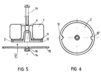
- Fig.5 eine Schnittdarstellung einer abgewandelten Ausführungsform einer Haltevorrichtung nach der Erfindung mit Befestigungsteilen zur Befestigung der Haltevorrichtung an einer Gehäusewandung und
- Fig.6 eine Ansicht der Halteplatte von unten in Richtung entsprechend dem Pfeil VI in Fig.5.
- Fi G .1 a Aufrißschnittdarstellung of the holding device according to the invention,
- Fi g .2 is a plan view of the holding device according to Figure 1 with removed toroidal core,
- Fi g .3 is a partial sectional view of a holding plate for the purposes of the invention, namely for use in a print fixing according to the section line III-III of Figure 4,
- 4 the associated top view of the carrier plate for the aforementioned implementation possibility,
- 5 shows a sectional view of a modified embodiment of a holding device according to the invention with fastening parts for fastening the holding device to a housing wall and
- 6 shows a view of the holding plate from below in the direction corresponding to arrow VI in FIG. 5.
In Fig. 1 ist eine Haltevorrichtung nach der Erfindung mit einem darauf befestigten bewickelten Ringkern 1 im Aufriß in einer Schnittdarstellung wiedergegeben. DieHaltevorrichtung besteht aus einer Trägerplatte 2, die im Bereich der Innenausnehmung des bewickelten Ringkernes 1 in einen Zentrierdorn übergeht, der, wie aus der Zeichnung ersichtlich, als Hohlzylinder ausgebildet ist.In Fig. 1, a holding device according to the invention with a wound toroidal core 1 attached thereon is shown in elevation in a sectional view. The holding device consists of a
Auf dieser Einheit aus Trägerplatte 2 und Zentrierdorn 3 ist der bewickelte Ringkern 3 aufgelegt und mittels einer Vergußmasse 4 befestigt und gehalten.The wound
In der Mitte weist die Trägerplatte 2 eine Bohrung 5 auf, die den Zugang für einen Schraubbolzen oder dergl. zu einer eingegossenen Sechskantmutter 6 ermöglicht. Damit kann die so ausgebildete Haltevorrichtung beispielsweise von unten mittels eines einfachen Schraubbolzens auf eine eben oder aber auch senkrecht verlaufende Trägerplatte geschraubt werden, ohne daß hierzu besondere Werkzeuge notwendig wären.In the middle, the
Um, insbesondere beim Anschrauben, ein Verdrehen der Trägerplatte 2 und damit des bewickelten Ringkernes 1 zu vermeiden und auch eine gute Auflage auf der TRägerplatte zu garantieren, sind auf der Unterseite der Trägerplatte 1 Abstützfüße 8 vorgesehen.In order, in particular when screwing on, to prevent the
Die Fig.2 zeigt in einer Draufsicht die Ausführung der Haltevorrichtung nach Fig. 1, wobei der bewickelte Ringkern 1 abgenommen ist. Aus der Fig.2 ist dabei zu ersehen, daß insgesamt 4 Abstützfüße vorgesehen sind.2 shows a top view of the design of the holding device according to FIG. 1, with the wound toroidal core 1 removed. From Figure 2 it can be seen that a total of 4 support feet are provided.
Die Fign. 3 und 4 zeigen in einer Aufrißschnittdarstel-lung (Fig. 3) und in einer Draufsicht (Fig. 4) eine andere Ausführungsform der Haltevorrichtung gemäß der Erfindung. Bei dieser Ausführunqsform sind nahe der Peripherie der Trägerplatte 2 Bohrungen 9 vorgesehen, in die bei Bedarf Lötstifte 10 eingesetzt werden können, an denen die Anschlußdrähte der Wicklung(en) des Ringkernes sowie die Verdrahtung mit weiteren Bauelementen oder Baugruppen erfolgen kann.The figures 3 and 4 show another embodiment of the holding device according to the invention in an elevation sectional view (FIG. 3) and in a top view (FIG. 4). In this embodiment, 2
Bei Verwendung einer Ausführungsform nach den Fig.3 u. 4 wird eine Trägerplatte 2 mit einem Durchmesser gewählt, der so groß ist, daß die ggf. eingesetzten Lötstifte außerhalb des Bereiches zu liegen kommen, der von einer bewickelten Ringkernspule eingenommen wird.When using an embodiment according to the Fig.3 u. 4, a
Im übrigen ist der Aufbau der gesamten Haltevorrichtung analog zu einem Aufbau, wie er anhand der Fign. 1 u. 2 erläutert wurdeOtherwise, the construction is the entire holding device similar to a structure as g n the basis of the Fi. 1 u. 2 has been explained
Für den auf dem Fachgebiet tätigen Fachmann ergibt sich, daß außer den bei der Eräuterung der Erfindung erwähnten Abwandlungen eine Reihe von weiteren Abwandlungen möglich sind. So ist es ohne erfinderisches Dazutun durchaus möglich, im Bereich der Stützfüße Haltefahnen oder auch Sechskant,Muttern, Schrauben mit ihren Köpfen oder derql. mit einzugießen, um die mit dem Ringkern bestückte Haltevorrichtung in einem Gerät, auf einer Leiterplatte oder dergl. befestigen zu können.It will be apparent to those skilled in the art that besides those in explaining the invention mentioned modifications a number of further modifications are possible. So it is quite possible without inventive intervention, in the area of the support feet holding flags or hexagon, nuts, screws with their heads or the like. with einzu g ow to be able to secure the fitted with the ring core supporting device in a device on a circuit board or the like..
In der Fig.5 ist eine abgewandelte Ausführungsform der Haltevorrichtung nach der Erfindung im Aufriß in einer Schnittdarstellung wiedergegeben. Bei dieser Realisierungsform ist auf der dem bewickelten Ringkern 1 zugewandten Seite der Trägerplatte 2 ein Ring 11 aus einem elastischen Material vorgesehen. Diese Maßnahme ist insbesondere dann von Vorteil, wenn die Trägerplatte relativ steif und die Oberfläche der Wicklungen auf dem Ringkern uneben sind, weil hierdurch ein gleichmäßiger Auflagedruck gegeben ist.5 shows a modified embodiment of the holding device according to the invention in elevation in a sectional view. In this embodiment, a ring 11 made of an elastic material is provided on the side of the
In der Fig. 5 ist dann noch gezeigt, wie ein gemäß der Erfindung gehaltener Kern beispielsweise an einer Gehäusewand 15 befestigt, nämlich angeschraubt werden kann, und zwareinfach dadurch, daß in dieser Gehäusewand eine Bohrung 16 angebracht wird, durch die ein von oben durch den Zentrierdorn geführter Schraubbolzen 13 gesteckt wird, auf den von unten eine Haltemutter 14 aufgeschraubt wird.In Fig. 5 is then still shown how a core held according to the invention, for example, attached to a
Um ein relatives Verdrehen des auf die Halteplatte 2 aufgebrachten Ringkernes zur Gehäusewandung auch bei der Montage zu verhindern, sind bei dieser Ausführungsform in der Halteplatte 2 Aussparungen 12 bzw. 12' vorgesehen, die mit - in der Figur nicht dargestellten - Haltenasen oder Haltevorsprüngen an der Gehäusewandung in Eingriff gebracht werden.In order to prevent a relative rotation of the ring core applied to the
Eine Ansicht einer Halteplatte mit derartigen Aussparungen 12 bzw. 12' zeigt Fig.6, wobei die Ansicht entsprechend dem Pfeil VI in Fig. 5 gewählt ist.A view of a holding plate with
Die Trägerplatte mit dem Zentrierdorn wird vorzugsweise aus einem gießbaren Kunststoff, insbesondere mit einem mit Butadien und Acrylnitril modifiziertem Polystyrol, wie er beispielsweise unter dem Warenzeichen Terluran auf dem Markt ist, gefertigt. Dabei kann es sich insbesondere bei Ringkernen mit sehr großem Eisenkern empfehlen, Verstärkungseinlagen, beispielsweise in Form von Glas- oder Kohlefasern usw. mit einzupressen, um der Trägerülatte eine den jeweiligen Gegebenheiten und Betriebsbedingungen angepaßte Festigkeit zu geben. Eine Verstärkung empfiehlt sich beispielsweise dann, wenn bei einem Einsatz auf Fahrzeugen usw. die Haltevorrichtung durch Stöße oder andere Einflüsse besonders beansprucht wird.The carrier plate with the centering mandrel is preferably made of a castable plastic, in particular with a polystyrene modified with butadiene and acrylonitrile, as is for example marketed under the trademark Terluran. It may be particularly advisable to press in reinforcing inserts, for example in the form of glass or carbon fibers, etc., in the case of toroidal cores with a very large iron core, in order to give the support plate a strength which is adapted to the particular circumstances and operating conditions. A reinforcement is recommended, for example, if the holding device is particularly stressed by shocks or other influences when used on vehicles, etc.
Claims (9)
Priority Applications (1)
| Application Number | Priority Date | Filing Date | Title |
|---|---|---|---|
| AT82109344T ATE17899T1 (en) | 1981-10-09 | 1982-10-08 | HOLDING DEVICE FOR TOROIDAL CORES WITH WINDINGS. |
Applications Claiming Priority (2)
| Application Number | Priority Date | Filing Date | Title |
|---|---|---|---|
| DE19813140221 DE3140221A1 (en) | 1981-10-09 | 1981-10-09 | HOLDING DEVICE FOR WINDING RING CORES |
| DE3140221 | 1981-10-09 |
Publications (2)
| Publication Number | Publication Date |
|---|---|
| EP0077050A1 true EP0077050A1 (en) | 1983-04-20 |
| EP0077050B1 EP0077050B1 (en) | 1986-02-05 |
Family
ID=6143783
Family Applications (1)
| Application Number | Title | Priority Date | Filing Date |
|---|---|---|---|
| EP82109344A Expired EP0077050B1 (en) | 1981-10-09 | 1982-10-08 | Holding device for annular cores provided with windings |
Country Status (3)
| Country | Link |
|---|---|
| EP (1) | EP0077050B1 (en) |
| AT (1) | ATE17899T1 (en) |
| DE (2) | DE3140221A1 (en) |
Cited By (1)
| Publication number | Priority date | Publication date | Assignee | Title |
|---|---|---|---|---|
| CN104979085A (en) * | 2014-04-14 | 2015-10-14 | 矢崎总业株式会社 | Coil fixation structure |
Families Citing this family (1)
| Publication number | Priority date | Publication date | Assignee | Title |
|---|---|---|---|---|
| EP0137867A1 (en) * | 1983-10-17 | 1985-04-24 | Wilhelm Sedlbauer GmbH | Fixing device for wound toroidal cores |
Citations (5)
| Publication number | Priority date | Publication date | Assignee | Title |
|---|---|---|---|---|
| US3210701A (en) * | 1962-05-14 | 1965-10-05 | Automatic Elect Lab | Wound toroidal core shell |
| DE1236643B (en) * | 1963-07-12 | 1967-03-16 | Siemens Ag | Instrument transformers in head design, in particular plastic-insulated current transformers |
| US3551864A (en) * | 1969-12-12 | 1970-12-29 | Pico Electronics Inc | Miniature inductive devices |
| FR2260269A7 (en) * | 1974-02-05 | 1975-08-29 | Transdurtor Ab | |
| US4054856A (en) * | 1976-09-08 | 1977-10-18 | Sundstrand Corporation | Current transformer assembly for dynamoelectric machines |
-
1981
- 1981-10-09 DE DE19813140221 patent/DE3140221A1/en not_active Withdrawn
-
1982
- 1982-10-08 DE DE8282109344T patent/DE3268985D1/en not_active Expired
- 1982-10-08 AT AT82109344T patent/ATE17899T1/en not_active IP Right Cessation
- 1982-10-08 EP EP82109344A patent/EP0077050B1/en not_active Expired
Patent Citations (5)
| Publication number | Priority date | Publication date | Assignee | Title |
|---|---|---|---|---|
| US3210701A (en) * | 1962-05-14 | 1965-10-05 | Automatic Elect Lab | Wound toroidal core shell |
| DE1236643B (en) * | 1963-07-12 | 1967-03-16 | Siemens Ag | Instrument transformers in head design, in particular plastic-insulated current transformers |
| US3551864A (en) * | 1969-12-12 | 1970-12-29 | Pico Electronics Inc | Miniature inductive devices |
| FR2260269A7 (en) * | 1974-02-05 | 1975-08-29 | Transdurtor Ab | |
| US4054856A (en) * | 1976-09-08 | 1977-10-18 | Sundstrand Corporation | Current transformer assembly for dynamoelectric machines |
Cited By (1)
| Publication number | Priority date | Publication date | Assignee | Title |
|---|---|---|---|---|
| CN104979085A (en) * | 2014-04-14 | 2015-10-14 | 矢崎总业株式会社 | Coil fixation structure |
Also Published As
| Publication number | Publication date |
|---|---|
| ATE17899T1 (en) | 1986-02-15 |
| EP0077050B1 (en) | 1986-02-05 |
| DE3268985D1 (en) | 1986-03-20 |
| DE3140221A1 (en) | 1983-08-11 |
Similar Documents
| Publication | Publication Date | Title |
|---|---|---|
| EP0576813B1 (en) | Electromagnet having an armature rod made from plastic | |
| DE4017260A1 (en) | Mfg. gradient coil arrangement for MRI - achieving high coil position accuracy using removable formers, adhesive and setting resin | |
| DE2715717C3 (en) | Anchor rail with rail bracket for a magnetic levitation vehicle | |
| DE102005058119A1 (en) | Mounting system for electrical transformer windings that are embedded in moulding resin with fixing points | |
| DE3127360C2 (en) | Casting mold for a stator of an electrical machine | |
| EP0077050B1 (en) | Holding device for annular cores provided with windings | |
| DE19840612A1 (en) | Holding device for holding workpieces in the form of flat sheet metal blanks | |
| DE2214537A1 (en) | LOCKING PANEL FOR SECURING ELECTRONIC ASSEMBLIES | |
| DE3517933C2 (en) | Lock mechanism with a pawl shaft | |
| EP0325736A2 (en) | Fastening of machine elements | |
| DE2800868A1 (en) | FASTENING ARRANGEMENT FOR CONVEYOR BELT CLEANING DEVICES | |
| DE3347096A1 (en) | Bearing, in particular footstep bearing or footstep and radial bearing for supporting shafts | |
| CH670327A5 (en) | ||
| DE4414951C1 (en) | Load selector or step selector for step transformers | |
| DE2735530C2 (en) | Clamping plate for a press mold lower part | |
| DE8129597U1 (en) | HOLDING DEVICE FOR WINDING RING CORES | |
| DE1449703C3 (en) | Device for adjusting and fastening at least one magnetic transfer head on a rotatable drum of a magnetic tape device | |
| DE3233920A1 (en) | SUPPORTING DEVICE FOR SUPPORTING LADDERS OUTSIDE WINDINGS IN TRANSFORMERS AND THROTTLE COILS | |
| DE8309239U1 (en) | TAPE REEL, IN PARTICULAR FOR MAGNETIC TAPES | |
| EP0583856A1 (en) | Door for a switchgear cabinet having a frame fixed on its inside | |
| DE3213512C1 (en) | Roller serving as a heat exchanger | |
| AT238279B (en) | Cable termination | |
| EP0251025A2 (en) | Attachment device for fastening a snap-in anchor in a metal prosthesis | |
| DE2103080C3 (en) | Molding box, preferably made of metal, for the production of moldings from concrete or the like | |
| DE3012165A1 (en) | GAS OR LIQUID INSULATED TRANSDUCER |
Legal Events
| Date | Code | Title | Description |
|---|---|---|---|
| PUAI | Public reference made under article 153(3) epc to a published international application that has entered the european phase |
Free format text: ORIGINAL CODE: 0009012 |
|
| AK | Designated contracting states |
Designated state(s): AT BE CH DE FR GB IT LI LU NL SE |
|
| 17P | Request for examination filed |
Effective date: 19830412 |
|
| ITF | It: translation for a ep patent filed |
Owner name: STUDIO JAUMANN |
|
| GRAA | (expected) grant |
Free format text: ORIGINAL CODE: 0009210 |
|
| AK | Designated contracting states |
Designated state(s): AT BE CH DE FR GB IT LI LU NL SE |
|
| REF | Corresponds to: |
Ref document number: 17899 Country of ref document: AT Date of ref document: 19860215 Kind code of ref document: T |
|
| REF | Corresponds to: |
Ref document number: 3268985 Country of ref document: DE Date of ref document: 19860320 |
|
| ET | Fr: translation filed | ||
| PG25 | Lapsed in a contracting state [announced via postgrant information from national office to epo] |
Ref country code: LU Free format text: LAPSE BECAUSE OF NON-PAYMENT OF DUE FEES Effective date: 19861031 |
|
| PLBI | Opposition filed |
Free format text: ORIGINAL CODE: 0009260 |
|
| 26 | Opposition filed |
Opponent name: TALEMA ELECTRONIK GMBH Effective date: 19861105 Opponent name: SCHUNTERMANN U. BENNINGHOVEN GMBH Effective date: 19861031 |
|
| NLR1 | Nl: opposition has been filed with the epo |
Opponent name: TALEMA ELECTRONIK GMBH Opponent name: SCHUNTERMANN U. BENNINGHOVEN GMBH |
|
| PLAB | Opposition data, opponent's data or that of the opponent's representative modified |
Free format text: ORIGINAL CODE: 0009299OPPO |
|
| R26 | Opposition filed (corrected) |
Opponent name: SCHUNTERMANN U. BENNINGHOVEN GMBH * 861105 TALEMA Effective date: 19861031 |
|
| PGFP | Annual fee paid to national office [announced via postgrant information from national office to epo] |
Ref country code: LU Payment date: 19900801 Year of fee payment: 9 |
|
| PGFP | Annual fee paid to national office [announced via postgrant information from national office to epo] |
Ref country code: FR Payment date: 19900806 Year of fee payment: 9 |
|
| PGFP | Annual fee paid to national office [announced via postgrant information from national office to epo] |
Ref country code: GB Payment date: 19900807 Year of fee payment: 9 |
|
| PGFP | Annual fee paid to national office [announced via postgrant information from national office to epo] |
Ref country code: AT Payment date: 19900808 Year of fee payment: 9 |
|
| PGFP | Annual fee paid to national office [announced via postgrant information from national office to epo] |
Ref country code: CH Payment date: 19900823 Year of fee payment: 9 |
|
| PGFP | Annual fee paid to national office [announced via postgrant information from national office to epo] |
Ref country code: SE Payment date: 19900926 Year of fee payment: 9 |
|
| PGFP | Annual fee paid to national office [announced via postgrant information from national office to epo] |
Ref country code: BE Payment date: 19901010 Year of fee payment: 9 |
|
| ITTA | It: last paid annual fee | ||
| PGFP | Annual fee paid to national office [announced via postgrant information from national office to epo] |
Ref country code: NL Payment date: 19901031 Year of fee payment: 9 |
|
| PGFP | Annual fee paid to national office [announced via postgrant information from national office to epo] |
Ref country code: DE Payment date: 19901221 Year of fee payment: 9 |
|
| RDAG | Patent revoked |
Free format text: ORIGINAL CODE: 0009271 |
|
| STAA | Information on the status of an ep patent application or granted ep patent |
Free format text: STATUS: PATENT REVOKED |
|
| REG | Reference to a national code |
Ref country code: CH Ref legal event code: PL |
|
| 27W | Patent revoked |
Effective date: 19900612 |
|
| GBPR | Gb: patent revoked under art. 102 of the ep convention designating the uk as contracting state | ||
| NLR2 | Nl: decision of opposition | ||
| BERE | Be: lapsed |
Owner name: WILHELM SEDLBAUER G.M.B.H. Effective date: 19911031 |
|
| EUG | Se: european patent has lapsed |
Ref document number: 82109344.0 Effective date: 19910703 |
|
| APAH | Appeal reference modified |
Free format text: ORIGINAL CODE: EPIDOSCREFNO |