EP0076897A1 - Latent heat accumulator, manufacturing process and uses thereof - Google Patents
Latent heat accumulator, manufacturing process and uses thereof Download PDFInfo
- Publication number
- EP0076897A1 EP0076897A1 EP82106953A EP82106953A EP0076897A1 EP 0076897 A1 EP0076897 A1 EP 0076897A1 EP 82106953 A EP82106953 A EP 82106953A EP 82106953 A EP82106953 A EP 82106953A EP 0076897 A1 EP0076897 A1 EP 0076897A1
- Authority
- EP
- European Patent Office
- Prior art keywords
- heat
- substance
- cells
- accumulator
- latent
- Prior art date
- Legal status (The legal status is an assumption and is not a legal conclusion. Google has not performed a legal analysis and makes no representation as to the accuracy of the status listed.)
- Granted
Links
Images
Classifications
-
- C—CHEMISTRY; METALLURGY
- C09—DYES; PAINTS; POLISHES; NATURAL RESINS; ADHESIVES; COMPOSITIONS NOT OTHERWISE PROVIDED FOR; APPLICATIONS OF MATERIALS NOT OTHERWISE PROVIDED FOR
- C09K—MATERIALS FOR MISCELLANEOUS APPLICATIONS, NOT PROVIDED FOR ELSEWHERE
- C09K5/00—Heat-transfer, heat-exchange or heat-storage materials, e.g. refrigerants; Materials for the production of heat or cold by chemical reactions other than by combustion
- C09K5/02—Materials undergoing a change of physical state when used
- C09K5/06—Materials undergoing a change of physical state when used the change of state being from liquid to solid or vice versa
- C09K5/063—Materials absorbing or liberating heat during crystallisation; Heat storage materials
-
- F—MECHANICAL ENGINEERING; LIGHTING; HEATING; WEAPONS; BLASTING
- F28—HEAT EXCHANGE IN GENERAL
- F28D—HEAT-EXCHANGE APPARATUS, NOT PROVIDED FOR IN ANOTHER SUBCLASS, IN WHICH THE HEAT-EXCHANGE MEDIA DO NOT COME INTO DIRECT CONTACT
- F28D20/00—Heat storage plants or apparatus in general; Regenerative heat-exchange apparatus not covered by groups F28D17/00 or F28D19/00
- F28D20/02—Heat storage plants or apparatus in general; Regenerative heat-exchange apparatus not covered by groups F28D17/00 or F28D19/00 using latent heat
- F28D20/023—Heat storage plants or apparatus in general; Regenerative heat-exchange apparatus not covered by groups F28D17/00 or F28D19/00 using latent heat the latent heat storage material being enclosed in granular particles or dispersed in a porous, fibrous or cellular structure
-
- Y—GENERAL TAGGING OF NEW TECHNOLOGICAL DEVELOPMENTS; GENERAL TAGGING OF CROSS-SECTIONAL TECHNOLOGIES SPANNING OVER SEVERAL SECTIONS OF THE IPC; TECHNICAL SUBJECTS COVERED BY FORMER USPC CROSS-REFERENCE ART COLLECTIONS [XRACs] AND DIGESTS
- Y02—TECHNOLOGIES OR APPLICATIONS FOR MITIGATION OR ADAPTATION AGAINST CLIMATE CHANGE
- Y02E—REDUCTION OF GREENHOUSE GAS [GHG] EMISSIONS, RELATED TO ENERGY GENERATION, TRANSMISSION OR DISTRIBUTION
- Y02E60/00—Enabling technologies; Technologies with a potential or indirect contribution to GHG emissions mitigation
- Y02E60/14—Thermal energy storage
Definitions
- the present invention relates to a heat accumulator and, in particular, to a heat accumulator apt to store considerable amounts of heat at a selected temperature.
- the latent heat storage systems which have so far found some practical application, are confined to the field of temperatures exceeding 900 °K (for instance, in the heat accumulators adopted in the solar concentration systems, especially in the space field).
- the object of the present invention is to overcome the aforespecified drawbacks, which have so far strongly limited the utilization of heat sources at low temperature, by providing a latent heat accumulator apt to store into a limited space considerable quantities of heat at a predetermined temperature, and in which the physical characteristics of the substance subject to cyclic changes of state are substantially free from phenomena of decay in the long run, independently of the number of cycles.
- Another object of the present invention is to indicate a process for the production of the aforespecified heat accumulator.
- a latent heat accumulator of the type utilizing a substance with a high latent melting heat per unit of volume and with a high thermal conductivity, characterized in that said substance is enclosed in a plurality of sealed cells formed of a material with high thermal conductivity and each having dimensions of the order of magnitude of centimeters, and in that said substance has a melting temperature included between 0°C and 100°C.
- said substance is a chemical compound included in the group consisting of hydrate salts and, in particular, hydrate phosphates, sulphates and sulphites, or else in the group constituted by the paraffines.
- the accumulator according to the present invention is formed of a plurality of cells C filled with a substance F having a high latent melting heat.
- the cells C are formed of a plastic material having the following characteristics: it is thermoformable, apt to be heat sealed and it has a high coefficient of thermal conductivity.
- a preferred material is constituted by coextruded, high-density polyethylene.
- coextruded is intended for a high-density polyethylene extruded simultaneously with a thin-film polyethylene, which perfectly adheres to the first, increasing its heat-sealing characteristics (obviously on the side ;-here the thin film is applied).
- the cells C enclose in their inner part a certain quantity of substance F with high latent melting heat, the melting temperature of which is included between 0°C and 100°C.
- substance F will preferably be selected among the chemical compounds belonging to the group comprising hydrate salts, hydrate phosphates, sulphates and sulphites, or else to the group constituted by the paraffines.
- All these products have a high latent melting heat per unit of volume (equal to an average of about 30-90 times the specific heat per unit of volume of water), and they also have melting temperatures included between 0°C and 100°C.
- the melting temperature of the substance F forms the parameter according to which each chemical compound is preferred for a specific application, as better explained hereinafter.
- this type of chemical compounds if subjected to a series of melting cycles and subsequent crystallization, may undergo - due to possible separations of the phases or evaporation of the components - a decay of its physical characteristics, particularly those specified heretofore, which condition the proper working thereof.
- the Applicant has now been able to establish, surprisingly, that if such chemical compounds are enclosed into sealed cells of small dimensions, the above drawback is substantially eliminated, that is, the decay of the physical characteristics of said chemical compounds occurs only after such a high number of cycles, as not to be felt in the practical uses.
- the volume of the cell C will have to be less than a critical volume equal to about 1 dm 3 .
- said volume will be far more limited, for istance comprised between 50 and 100 cc.
- the substance F may perform a very high number of cycles - for instance, up to about 3500 cycles - without undergoing any altering. Since, in current applications, such a number of cycles corresponds to a period of time of about a hundred years, it can be understood how the desired working of the substance F is practically unlimited.
- the cells C are formed according to a particularly simple process, comprising the following stages:
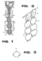
- the machine illustrated in figure 1 substantially comprises a head 1, which provides to pour the substance F inside the sheet 2 of plastic material, having a tubular shape.
- the head 1 may be constituted by an extruder, apt to extrude the tubular sheet 2 simultaneously with the feeding of the substance F.
- the sealing operation of the single cells takes place in 3 and 4, thereby obtaining chains of cells, as illustrated in figure 2.
- These chains of cells C can have an end tailpiece 5, apt to be folded over.
- the tailpiece 5 allots to promptly hang the chains of cells C onto bars 6, or other hooking means, provided at the top of heat storage reservoirs (not shown).
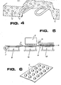
- the machine illustrated in figure 5 comprises instead a first roll 7 of plastic sheet material, into which are impressed in 3, by thermoforming, a series of cavities 9 of the dimensions desired for the cells C. Said cavities are filled in 10, and subsequently the whole sheet is covered in 12 with a second sheet of plastic material coming from the roll 11. Finally, the two sheets are reciprocally sealed in 13, in the contact areas surrounding the filled cavities. This allows to obtain a continuous belt of cells C, a portion of which is shown in figure 6, positioned upside-down in respect of the position with which it comes out of the machine for its production.
- the heat accumulator according to the present invention finds its best use - as already seen in the introductory part - in all those cases in which the temperature of the heat source is too low to be able to be utilized in any other way.
- This accumulator in fact, by making use of the high latent heat of the substance F, allows to store large amounts of heat in a small space, restoring said heat at the most appropriate moment.
- the accumulators may be placed in direct contact with any heat source, as for example sun radiation, industrial heat excesses, thermal exchange fluids, and the like.
- any heat source as for example sun radiation, industrial heat excesses, thermal exchange fluids, and the like.
- this latter absorbs heat and gradually melts. This heat is automatically and promptly restored, by renewed solidification of the substance F, as soon as the temperature drops below said exchange temperature.
- the amount of heat absorbed per unit of volume is obviously in relation to the value of the latent heat of each single compound forming the substance F.
- the heretofore specified exchange temperature is the temperature at which the heat backflow between substance F and environment takes place (here and hereinafter it is meant - unless otherwise indicated - that the substance F absorbs or transfers heat exclusively under form of latent heat). If the environment has temperatures below the exchange temperature, heat is transferred from the substance F to the environment through a gradual solidification of the substance itself. Viceversa, if the environment has a temperature which is higher than the exchange temperature, heat is transferred from the environment to the substance F.
- the exchange temperature should coincide with the melting temperature of the substance F.
- the Applicant was actually able to ascertain, experimentally, that the exchange temperature is usually below the melting temperature and that it depends, as well as from this latter, also from the amount of substance F present in the support (slab, wall or the like), from the thickness of said support and, finally, from the total coefficient of thermal conductivity K of the support itself.
- the substance F is apt to absorb heat even at temperatures up to 15°-20°C lower than the melting temperature, in conditions of slow cooling or heating of the environment, while in fast cooling conditions the substance promptly (within a few seconds) reaches its own melting temperature.
- This last characteristic is particularly interesting because, in case of a sudden drop of the external temperature, the substance F reaches its own melting temperature and it is therefore apt to transfer large quantities of heat in a short time (due to the increase in the difference of temperature) restoring in the environment the desired temperature conditions.
- the accumulator according to the present invention lends itself particularly well for use in applications which require the temperature to keep constant around a predetermined value, for instance typically in the conditioning of rooms, where it will be able to perform the double function of producing heat in the winter season and of absorbing the same in the summer season.
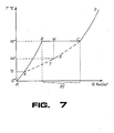
- Fig. 7 shows a qualitative graph of a heating curve of a typical substance F, with melting point of 32°C.
- abscissae are reported the quantities of heat Q in kcal/dm 3 , while the ordinates indicate the temperature T in °C.
- the horizontal line B-C represents the melting at a constant temperature, supplying 85 kcal/dm 3
- the line C-D represents the heating of the substance F completely melted.
- the exchange temperature of the substance F - but only, as said, in slow cooling eventually followed by slow heating conditions - can be set at any point of this range of temperatures, by acting on the parameters already seen heretofore, which can be suitably programmed at the planning stage.
- the exchange temperature being set at 22°C (a typical value for the conditioning of rooms)
- the working area of the substance F will cover the arc of the curve Y-Z.
- any rise of temperature above the exchange temperature will cause a partial melting of the substance F with conversion of the heat of the atmosphere into latent heat of the substance F.
- the temperature increase of the substance F, resulting from this melting, is very limited and does not exceed - in the course of a particularly hot day - a few tenths of a degree. It is therefore quite evident how, in this way, it is possible to obtain a perfect conditioning action, in the sense heretofore specified.
- the single cells C When applied for conditioning rooms, the single cells C (separated the ones from the others, as shown in figure 3) may be mingled directly with concrete, or the like, for casting slabs or walls of buildings to be conditioned (figure 4).
- the cells C in the shape shown in figure 6) may constitute a continuous layer positioned between the slab and the finishing mantle of floorings. This arrangement allows to obtain inside the buildings a practically constant temperature value compensating the temperature differences tied to the day-night cycle. Furthermore, this arrangement - in association with special central storage reservoirs forming large reserves of latent heat - allows to distribute the heat required for heating rooms during the winter season.
- the cells C are arranged as illustrated in figure 2, or else in the form of belts (figure 6) placed astride of the bars 6, inside reservoirs filled with a working fluid (for instance water) apt to constitute the heat transmission means between the single cells C of each reservoir, and between these cells and the cells C scattered into the walls of the building.
- a working fluid for instance water
- the present invention has fully attained its intended objects. It in fact provides a heat accumulator which is apt to store, in a limited space large quantities of heat, at a temperature prearranged according to the temperature of the heat source being utilized and according to the requirements of use. Furthermore, as seen, the accumulator has a very long and practically unlimited life.
- the invention is particularly suited for solar plants without concentration of the radiations, to which it confers a high degree of autonomy, compensating not only the temperature differences connected with the day-night period; but above all the radiation shortages connected with the autumn-winter periods.
Abstract
Description
- The present invention relates to a heat accumulator and, in particular, to a heat accumulator apt to store considerable amounts of heat at a selected temperature.
- The problem of making use of the heat available at low temperatures (for instance, at room temperature or a few tens of °C higher) has always been difficult to solve. This not so much for lack of possible utilization of the heat at this temperature (it is in fact sufficient to think of the heating of environments, or of the production of hot water for sanitary use), but rather owing to the difficulty of accumulating said heat during the periods and in the places where it. is produced, so as to then be able to restore it when and where necessary.
- It is well known, in fact, that the residual heat of a large number of industrial processes constitutes, in most cases, a processing "rejection" which has to be eliminated in the air or in water, with consequent heat pollution phenomena. The utilization of this heat for the heating of rooms or of water is often neither possible nor economically convenient, due to the difficulty of conciliating the requirements of consumption and those of heat production and thus, as a matter of fact, due to the unavailability of a satisfactory heat storage system.
- Even in plants which make use of solar energy - to which the invention specifically, though not exclusively, refers - the fundamental problem, still to be solved, is that concerning the storage of the heat absorbed by the collecting surfaces and not immediately used up. For this purpose, one simply uses at present large insulated reservoirs connected to the circuit of the working fluid (generally consisting of water) and filled by the same. This system, however, as well as taking up considerable space, is usually apt to satisfy only the requirements of storage connected to the day-and-night period, for what concerns the production of hot water for sanitary use. Whereas, the problem of producing an accumulator, allowing to store during the summer period an amount of heat such as to enable hot water to be delivered during the winter period without resorting to any other sources of energy, still has to be solved, unless one were to use reservoirs having such dimensions and characteristics of insulation, as to result extremely costly.
- Even more so, on account of the foregoing, it has been impossible up-to-date to make use of solar energy for heating environments during the winter season. In fact, the solutions proposed - all on an experimental level - require appropriately conceived structures, having such costs and structural characteristics as to make it practically unthinkable for them to be adopted in the normal building industry.
- The drawbacks evidenced by the current heat storage devices, namely the incapability to accumulate considerable amounts of heat in a limited space, are substantially due to the fact that heat is stored therein under form of specific heat.
- This latter in fact, is given by the product of the heat storage fluid mass multiplied by its specific heat and by the difference in temperature between the heat storage fluid and the environment. Consequently, the only variable on which it is nomally possible to operate is the heat storage fluid mass, in that the temperature difference is imposed - seen that, as stated, low temperature plants are involved - and it is generally rather low (from a few °C up to a few tens of °C), while the specific heat is anyhow very low for all the fluids of practical interest (it in fact has its highest value for water with 1 keal/dm3).
- In order to overcome these drawbacks, it has been thought to adopt storage systems which store the heat under form of latent heat (in particular, melting heat or heat of crystallization), and not under form of specific heat. The advantages of this choice are evident. The latent heats per unit of volume are in fact far higher than the corresponding specific heats. Furthermore, they allow to transfer the heat at a constant temperature, already known at the planning stage.
- The latent heat storage systems, which have so far found some practical application, are confined to the field of temperatures exceeding 900 °K (for instance, in the heat accumulators adopted in the solar concentration systems, especially in the space field).
- Various attempts have also been made to obtain heat accumulators using the latent heat of chemical substances having a lower melting temperature (for instance, Glauber salt with 32.4°C melting point). In fact, these accumulators appear to be particularly suited for use in the solar plants, wherein no concentration of sun radiations is carried out.
- Nevertheless, the chemical compounds having a high latent melting heat at these temperatures, combined with an acceptable cost, evidence features of evaporation and/or. chemical unstability, which alter their physical characteristics already after only 30 or 40 melting and subsequent solidification cycles; they are therefore practically useless for the above mentioned purposes.
- In consideration of the above, these products have so far found no practical application, in spite of the remarkable advantages which they could on the other hand provide.
- It will be noted that, so far, only the case of latent melting heat has been intentionally mentioned, as the latent heat of vaporization cannot be conveniently utilized owing to the wide volumetric variations between the liquid phase and the gaseous phase.
- The object of the present invention is to overcome the aforespecified drawbacks, which have so far strongly limited the utilization of heat sources at low temperature, by providing a latent heat accumulator apt to store into a limited space considerable quantities of heat at a predetermined temperature, and in which the physical characteristics of the substance subject to cyclic changes of state are substantially free from phenomena of decay in the long run, independently of the number of cycles.
- Another object of the present invention is to indicate a process for the production of the aforespecified heat accumulator.
- The aforementioned objects are obtained, according to the present invention, by means of a latent heat accumulator of the type utilizing a substance with a high latent melting heat per unit of volume and with a high thermal conductivity, characterized in that said substance is enclosed in a plurality of sealed cells formed of a material with high thermal conductivity and each having dimensions of the order of magnitude of centimeters, and in that said substance has a melting temperature included between 0°C and 100°C.
- According to a main characteristic of the invention, said substance is a chemical compound included in the group consisting of hydrate salts and, in particular, hydrate phosphates, sulphates and sulphites, or else in the group constituted by the paraffines.
- The use of the accumulator according to the present invention becomes particularly convenient, simple and quick, if the accumulator itself is manufactured according to a preferred process comprising the following stages:
- - forming a plurality of small cavities into at least one sheet of a thermoformable plastic material;
- - filling said cavities with said substance having a high latent melting heat, at the fluid state;
- - heat sealing said cavities, under partial vacuum, so as to form a plurality of sealed cells, filled with said substance and practically having no air-locks.
- The invention rill anyhow be described in further detail, with reference to some preferred embodiments thereof, shown in the accompanying drawings, in which:
- Fig. 1 is a diagrammatic view showing a machine for the continuous production of the sealed cells forming heat accumulator according to the present invention;
- Fig. 2 illustrates a method for hanging chains of cells inside a heat storage reservoir (not shown);
- Fig. 3 shows a single cell as used in mixing with concrete and the like;
- Fig. 4 schematically shows a concrete slab incorporating a plurality of cells identical to that illustrated in figure 3;
- Fig. 5 is a schematic view showing another machine for the continuous production of the sealed cells forming the heat accumulator according to the present invention;
- Fig. 6 shows part of a continuous belt of cells produced with the machine of figure 5; and
- Fig. 7 is a graph reporting temperature curves in function of the heat exchanged per unit of volume, of one of the chemical substances used in the present invention. The curves illustrate a hypothesis of behaviour of this substance.
- The accumulator according to the present invention is formed of a plurality of cells C filled with a substance F having a high latent melting heat.
- The cells C are formed of a plastic material having the following characteristics: it is thermoformable, apt to be heat sealed and it has a high coefficient of thermal conductivity. A preferred material is constituted by coextruded, high-density polyethylene. The term "coextruded" is intended for a high-density polyethylene extruded simultaneously with a thin-film polyethylene, which perfectly adheres to the first, increasing its heat-sealing characteristics (obviously on the side ;-here the thin film is applied).
- The cells C enclose in their inner part a certain quantity of substance F with high latent melting heat, the melting temperature of which is included between 0°C and 100°C. Various chemical compounds are apt to fulfil these conditions. The substance F will preferably be selected among the chemical compounds belonging to the group comprising hydrate salts, hydrate phosphates, sulphates and sulphites, or else to the group constituted by the paraffines. Among the indicated products, the following have been tested with success: decahydrate sodium sulphate m.p. 32.4°
C Q 1 85 kcal/dm3 dodecahydrate bisodium phosphate m.p. 36 °C Q1 90 kcal/dm3 heptahydrate bisodium phosphate m.p. 48 °C Q1 90 kcal/dm3 where m.p. is the melting point of the substance, and Q1 is its latent melting heat per unit of volume. - All these products have a high latent melting heat per unit of volume (equal to an average of about 30-90 times the specific heat per unit of volume of water), and they also have melting temperatures included between 0°C and 100°C. The melting temperature of the substance F forms the parameter according to which each chemical compound is preferred for a specific application, as better explained hereinafter.
- As previously stated, this type of chemical compounds, if subjected to a series of melting cycles and subsequent crystallization, may undergo - due to possible separations of the phases or evaporation of the components - a decay of its physical characteristics, particularly those specified heretofore, which condition the proper working thereof. The Applicant has now been able to establish, surprisingly, that if such chemical compounds are enclosed into sealed cells of small dimensions, the above drawback is substantially eliminated, that is, the decay of the physical characteristics of said chemical compounds occurs only after such a high number of cycles, as not to be felt in the practical uses.
- In particular, the volume of the cell C will have to be less than a critical volume equal to about 1 dm3. Preferably, said volume will be far more limited, for istance comprised between 50 and 100 cc. In these conditions, the substance F may perform a very high number of cycles - for instance, up to about 3500 cycles - without undergoing any altering. Since, in current applications, such a number of cycles corresponds to a period of time of about a hundred years, it can be understood how the desired working of the substance F is practically unlimited.
- Increasingly smaller volumes of the cells C involve an increase in the number of cycles, which the substance F can perform without undergoing any altering. On the other hand, a reduction in the size of the cells C involves an increase in the total production costs thereof. It will thus be necessary to find an economical "optimum" arrangement to determine the ideal size of the cells C, taking also into account the requirements dictated by the various types of uses.
- The cells C are formed according to a particularly simple process, comprising the following stages:
- - forming a plurality of small cavities into at least one sheet of thermoformable plastic material;
- - filling said cavities ith said substance F having a high latent melting heat, at a temperature above the melting point of said substance, so as to keep it at the fluid state during the filling operations;
- - heat sealing said cavities, under partial vacuum, so as to form a plurality of sealed cells C, filled with said substance F and practically having no air locks.
- Two different machines, apt to carry out this process, are schematically illustrated in figures 1 and 5. The two machines produce cells C with different final shapes, which can be suited for diffe- rent applications.
- The machine illustrated in figure 1 substantially comprises a
head 1, which provides to pour the substance F inside thesheet 2 of plastic material, having a tubular shape. Thehead 1 may be constituted by an extruder, apt to extrude thetubular sheet 2 simultaneously with the feeding of the substance F. The sealing operation of the single cells takes place in 3 and 4, thereby obtaining chains of cells, as illustrated in figure 2. - These chains of cells C can have an
end tailpiece 5, apt to be folded over. Thetailpiece 5 allots to promptly hang the chains of cells C onto bars 6, or other hooking means, provided at the top of heat storage reservoirs (not shown). - The machine illustrated in figure 5 comprises instead a
first roll 7 of plastic sheet material, into which are impressed in 3, by thermoforming, a series of cavities 9 of the dimensions desired for the cells C. Said cavities are filled in 10, and subsequently the whole sheet is covered in 12 with a second sheet of plastic material coming from theroll 11. Finally, the two sheets are reciprocally sealed in 13, in the contact areas surrounding the filled cavities. This allows to obtain a continuous belt of cells C, a portion of which is shown in figure 6, positioned upside-down in respect of the position with which it comes out of the machine for its production. - Evidently, the aforedescribed machines are only some possible examples of carrying out the above illustrated process, of which there may obviously be other embodiments, according also to the shape desired for the cells C.
- The heat accumulator according to the present invention finds its best use - as already seen in the introductory part - in all those cases in which the temperature of the heat source is too low to be able to be utilized in any other way. This accumulator, in fact, by making use of the high latent heat of the substance F, allows to store large amounts of heat in a small space, restoring said heat at the most appropriate moment.
- The accumulators may be placed in direct contact with any heat source, as for example sun radiation, industrial heat excesses, thermal exchange fluids, and the like. In the presence of temperatures higher than the exchange temperature of the substance F (defined hereinafter), this latter absorbs heat and gradually melts. This heat is automatically and promptly restored, by renewed solidification of the substance F, as soon as the temperature drops below said exchange temperature. The amount of heat absorbed per unit of volume is obviously in relation to the value of the latent heat of each single compound forming the substance F.
- The heretofore specified exchange temperature is the temperature at which the heat backflow between substance F and environment takes place (here and hereinafter it is meant - unless otherwise indicated - that the substance F absorbs or transfers heat exclusively under form of latent heat). If the environment has temperatures below the exchange temperature, heat is transferred from the substance F to the environment through a gradual solidification of the substance itself. Viceversa, if the environment has a temperature which is higher than the exchange temperature, heat is transferred from the environment to the substance F.
- The aforementioned characteristics would lead to the conclusion that the exchange temperature should coincide with the melting temperature of the substance F. Whereas, the Applicant was actually able to ascertain, experimentally, that the exchange temperature is usually below the melting temperature and that it depends, as well as from this latter, also from the amount of substance F present in the support (slab, wall or the like), from the thickness of said support and, finally, from the total coefficient of thermal conductivity K of the support itself.
- Always experimentally, it has been able to establish, through special temperature probes, that the substance F is apt to absorb heat even at temperatures up to 15°-20°C lower than the melting temperature, in conditions of slow cooling or heating of the environment, while in fast cooling conditions the substance promptly (within a few seconds) reaches its own melting temperature.
- This last characteristic is particularly interesting because, in case of a sudden drop of the external temperature, the substance F reaches its own melting temperature and it is therefore apt to transfer large quantities of heat in a short time (due to the increase in the difference of temperature) restoring in the environment the desired temperature conditions.
- On account of these characteristics, the accumulator according to the present invention lends itself particularly well for use in applications which require the temperature to keep constant around a predetermined value, for instance typically in the conditioning of rooms, where it will be able to perform the double function of producing heat in the winter season and of absorbing the same in the summer season.
- A possible theoretical hypothesis will now be given apt to justify the apparently anomalous behaviour of the substance F forming the accumulator according to the present invention, that is, its capability to absorb heat, under form of latent heat, even at temperatures below the melting temperature.
- Fig. 7 shows a qualitative graph of a heating curve of a typical substance F, with melting point of 32°C. In abscissae are reported the quantities of heat Q in kcal/dm3, while the ordinates indicate the temperature T in °C.
- The line A-B represents the heating of the substance F at the solid state from T = 0° to T = 32° (melting temperature). The horizontal line B-C represents the melting at a constant temperature, supplying 85 kcal/dm3, and finally, the line C-D represents the heating of the substance F completely melted.
- One assumes the presence of a metastable branch C-X, which appears in conditions of a slow cooling, eventually followed by an equally slow heating. The presence of said branch justifies the fact that latent heat is not exclusively exchanged at the temperature of 320, but in a range of temperatures included between 32° and a temperature T , which cannot be exactly defined but which anyhow varies between 8° and 150.
- The exchange temperature of the substance F - but only, as said, in slow cooling eventually followed by slow heating conditions - can be set at any point of this range of temperatures, by acting on the parameters already seen heretofore, which can be suitably programmed at the planning stage. In the event of the exchange temperature being set at 22°C (a typical value for the conditioning of rooms), the working area of the substance F will cover the arc of the curve Y-Z. The result is that, in conditions of high insolation during the summer period, any rise of temperature above the exchange temperature will cause a partial melting of the substance F with conversion of the heat of the atmosphere into latent heat of the substance F. The temperature increase of the substance F, resulting from this melting, is very limited and does not exceed - in the course of a particularly hot day - a few tenths of a degree. It is therefore quite evident how, in this way, it is possible to obtain a perfect conditioning action, in the sense heretofore specified.
- It should furthermore be noted that this hyphothesis satisfactorily explains the behaviour of the substance F in the event of sudden cooling. In fact, in this case (for instance during a strong summer storm), the substance F abandons the state of unstable equilibrium relative to the curve C-X, and immediately moves to the corresponding stable condition W at the temperature of 32°C, due to the supply of heat deriving from the simultaneous solidification of a part of said substance F.
- When applied for conditioning rooms, the single cells C (separated the ones from the others, as shown in figure 3) may be mingled directly with concrete, or the like, for casting slabs or walls of buildings to be conditioned (figure 4). Alternatively, the cells C (in the shape shown in figure 6) may constitute a continuous layer positioned between the slab and the finishing mantle of floorings. This arrangement allows to obtain inside the buildings a practically constant temperature value compensating the temperature differences tied to the day-night cycle. Furthermore, this arrangement - in association with special central storage reservoirs forming large reserves of latent heat - allows to distribute the heat required for heating rooms during the winter season.
- In such central heat storage reservoirs, the cells C are arranged as illustrated in figure 2, or else in the form of belts (figure 6) placed astride of the bars 6, inside reservoirs filled with a working fluid (for instance water) apt to constitute the heat transmission means between the single cells C of each reservoir, and between these cells and the cells C scattered into the walls of the building.
- By way of example, we are giving hereunder the formulas of some preferred types of substances F, indicating - in their order - the melting temperature, the latent heat in kcal/dm3, and the exchange temperature in °C. For each fomula, the field of application is indicated:
- a) 32/35/22 and 36/90/36 for the heating of rooms, with positioning of the cells C within the concrete elements forming the buildings to be conditioned (preferably floorings). The first formula is adopted in the case of residences, industrial plants and the like. The second formula is typically studied for application to greenhouses or other similar constructions having the same heating requirements;
- b) 48/90/55 for storing hot water for sanitary uses and for heat storage processes and thermomixing in general (central heat storage reservoirs). In this case the exchange temperature is controlled by means of a thermostat, which circulates the hot water coming from the heat collectors only when its temperature exceeds the exchange temperature. This latter is then determined so as to provide a sufficient temperatures jump in respect of the melting temperature of the substance F.
- Obviously, other types of substances F, with different formulas, may be prearranged for applications which require different operative temperatures; for instance, a formula of the type 32/35/10 could be perfectly suited to prevent the forming of ice onto viaducts, or in other similar special applications.
- From the foregoing, it is undoubted that the present invention has fully attained its intended objects. It in fact provides a heat accumulator which is apt to store, in a limited space large quantities of heat, at a temperature prearranged according to the temperature of the heat source being utilized and according to the requirements of use. Furthermore, as seen, the accumulator has a very long and practically unlimited life.
- The invention is particularly suited for solar plants without concentration of the radiations, to which it confers a high degree of autonomy, compensating not only the temperature differences connected with the day-night period; but above all the radiation shortages connected with the autumn-winter periods.
- The invention has been described with reference to some preferred embodiments thereof, but it is evident that there may be other embodiments differing from the same, arising from requirements of application, within reach of an expert in the art and thus all falling within the scope of the invention itself.
Claims (16)
Priority Applications (1)
| Application Number | Priority Date | Filing Date | Title |
|---|---|---|---|
| AT82106953T ATE19646T1 (en) | 1981-08-19 | 1982-08-06 | LATENT HEAT STORAGE, PROCESS FOR ITS MANUFACTURE AND USE. |
Applications Claiming Priority (2)
| Application Number | Priority Date | Filing Date | Title |
|---|---|---|---|
| CH5351/81 | 1981-08-19 | ||
| CH535181 | 1981-08-19 |
Publications (2)
| Publication Number | Publication Date |
|---|---|
| EP0076897A1 true EP0076897A1 (en) | 1983-04-20 |
| EP0076897B1 EP0076897B1 (en) | 1986-05-07 |
Family
ID=4292115
Family Applications (1)
| Application Number | Title | Priority Date | Filing Date |
|---|---|---|---|
| EP82106953A Expired EP0076897B1 (en) | 1981-08-19 | 1982-08-06 | Latent heat accumulator, manufacturing process and uses thereof |
Country Status (7)
| Country | Link |
|---|---|
| EP (1) | EP0076897B1 (en) |
| AT (1) | ATE19646T1 (en) |
| AU (1) | AU559354B2 (en) |
| BR (1) | BR8204808A (en) |
| DE (1) | DE3270995D1 (en) |
| NZ (1) | NZ201549A (en) |
| ZA (1) | ZA825765B (en) |
Cited By (20)
| Publication number | Priority date | Publication date | Assignee | Title |
|---|---|---|---|---|
| EP0109043A1 (en) * | 1982-11-13 | 1984-05-23 | Forschungszentrum Jülich Gmbh | Latent heat storage device with a salt hydrate or a mixture of salt hydrates and salts |
| FR2547334A1 (en) * | 1983-06-13 | 1984-12-14 | Pennwalt Corp | COMPOSITE THERMAL ENERGY STORAGE PRODUCT, CONCRETE OR PLASTER BUILDING MEMBER INCLUDING THE PRODUCT AND PRODUCT MANUFACTURING METHOD |
| EP0248030A1 (en) * | 1985-11-22 | 1987-12-09 | The University Of Dayton | Polyethylene composites containing a phase change material |
| AU589987B2 (en) * | 1985-08-09 | 1989-10-26 | Interteatherm Anstalt | Process for manufacturing hydrate salts-base granule-shaped thermal energy accumulators with an adherent hermetic coating, accumulators obtained by said process and their use |
| EP0344014A2 (en) * | 1988-05-27 | 1989-11-29 | The University Of Dayton | Method of making Polyolefin composites containing a phase change material |
| EP0764081A1 (en) * | 1994-04-25 | 1997-03-26 | Gateway Technologies, Inc. | Thermal barriers for buildings, appliances and textiles |
| WO2001006195A1 (en) * | 1999-07-19 | 2001-01-25 | The University Of Dayton | Heat storage pellets of phase change material and method of manufacturing same |
| WO2002042705A3 (en) * | 2000-11-23 | 2003-01-30 | Rubitherm Gmbh | Latent-heat accumulator body |
| DE102009032918A1 (en) * | 2009-07-14 | 2011-01-20 | Rehau Ag + Co. | Small volume PCM capsule, process for their preparation and this comprehensive latent heat storage |
| WO2012139013A3 (en) * | 2011-04-06 | 2012-12-27 | Dow Global Technologies Llc | Apparatus, systems and methods for dispensing phase change material as liquid |
| WO2011007009A3 (en) * | 2009-07-17 | 2013-03-07 | Gmeiner Emma | Solar heating system, air-conditioning system and accumulator heating plate therefor |
| US10036574B2 (en) | 2013-06-28 | 2018-07-31 | British American Tobacco (Investments) Limited | Devices comprising a heat source material and activation chambers for the same |
| US10542777B2 (en) | 2014-06-27 | 2020-01-28 | British American Tobacco (Investments) Limited | Apparatus for heating or cooling a material contained therein |
| US11064725B2 (en) | 2015-08-31 | 2021-07-20 | British American Tobacco (Investments) Limited | Material for use with apparatus for heating smokable material |
| US11241042B2 (en) | 2012-09-25 | 2022-02-08 | Nicoventures Trading Limited | Heating smokeable material |
| US11452313B2 (en) | 2015-10-30 | 2022-09-27 | Nicoventures Trading Limited | Apparatus for heating smokable material |
| US11659863B2 (en) | 2015-08-31 | 2023-05-30 | Nicoventures Trading Limited | Article for use with apparatus for heating smokable material |
| US11672279B2 (en) | 2011-09-06 | 2023-06-13 | Nicoventures Trading Limited | Heating smokeable material |
| US11825870B2 (en) | 2015-10-30 | 2023-11-28 | Nicoventures Trading Limited | Article for use with apparatus for heating smokable material |
| US11924930B2 (en) | 2015-08-31 | 2024-03-05 | Nicoventures Trading Limited | Article for use with apparatus for heating smokable material |
Families Citing this family (2)
| Publication number | Priority date | Publication date | Assignee | Title |
|---|---|---|---|---|
| AU601907B2 (en) * | 1986-04-09 | 1990-09-20 | Kubota Tekko Kabushiki Kaisha | Latent heat storage capsules containing heat-storage composition and temperature control apparatus using said capsules |
| NL2004246C2 (en) * | 2010-02-15 | 2011-08-16 | L G J Wolters Beheer Lichtenvoorde B V | Heat storage material and its method of manufacturing. |
Citations (4)
| Publication number | Priority date | Publication date | Assignee | Title |
|---|---|---|---|---|
| DE2552698A1 (en) * | 1975-11-25 | 1977-06-02 | Erno Raumfahrttechnik Gmbh | Large capacity heat storage device - has filled hollow elastic balls for infill in side insulating container |
| DE2741829A1 (en) * | 1977-09-16 | 1979-03-22 | Dornier System Gmbh | Latent heat storage material of encapsulated wax in liquid medium - allowing heat transfer by convection |
| FR2428223A1 (en) * | 1978-06-09 | 1980-01-04 | Armines | Isothermal heat storage unit - allowing heat exchange between material changing state and heat transfer liq., has material in several enclosures maximising transfer rate |
| DE3016730A1 (en) * | 1979-05-01 | 1981-06-11 | Pipe Systems, Inc., Fenton, Miss. | Heat store comprising thin-walled polyethylene tube - almost filled with calcium chloride hexa:hydrate and sealed with same polymer caps (SE 1.12.80) |
-
1982
- 1982-08-06 AT AT82106953T patent/ATE19646T1/en not_active IP Right Cessation
- 1982-08-06 DE DE8282106953T patent/DE3270995D1/en not_active Expired
- 1982-08-06 EP EP82106953A patent/EP0076897B1/en not_active Expired
- 1982-08-09 ZA ZA825765A patent/ZA825765B/en unknown
- 1982-08-10 NZ NZ201549A patent/NZ201549A/en unknown
- 1982-08-12 AU AU87097/82A patent/AU559354B2/en not_active Ceased
- 1982-08-17 BR BR8204808A patent/BR8204808A/en not_active IP Right Cessation
Patent Citations (4)
| Publication number | Priority date | Publication date | Assignee | Title |
|---|---|---|---|---|
| DE2552698A1 (en) * | 1975-11-25 | 1977-06-02 | Erno Raumfahrttechnik Gmbh | Large capacity heat storage device - has filled hollow elastic balls for infill in side insulating container |
| DE2741829A1 (en) * | 1977-09-16 | 1979-03-22 | Dornier System Gmbh | Latent heat storage material of encapsulated wax in liquid medium - allowing heat transfer by convection |
| FR2428223A1 (en) * | 1978-06-09 | 1980-01-04 | Armines | Isothermal heat storage unit - allowing heat exchange between material changing state and heat transfer liq., has material in several enclosures maximising transfer rate |
| DE3016730A1 (en) * | 1979-05-01 | 1981-06-11 | Pipe Systems, Inc., Fenton, Miss. | Heat store comprising thin-walled polyethylene tube - almost filled with calcium chloride hexa:hydrate and sealed with same polymer caps (SE 1.12.80) |
Cited By (23)
| Publication number | Priority date | Publication date | Assignee | Title |
|---|---|---|---|---|
| EP0109043A1 (en) * | 1982-11-13 | 1984-05-23 | Forschungszentrum Jülich Gmbh | Latent heat storage device with a salt hydrate or a mixture of salt hydrates and salts |
| FR2547334A1 (en) * | 1983-06-13 | 1984-12-14 | Pennwalt Corp | COMPOSITE THERMAL ENERGY STORAGE PRODUCT, CONCRETE OR PLASTER BUILDING MEMBER INCLUDING THE PRODUCT AND PRODUCT MANUFACTURING METHOD |
| AU589987B2 (en) * | 1985-08-09 | 1989-10-26 | Interteatherm Anstalt | Process for manufacturing hydrate salts-base granule-shaped thermal energy accumulators with an adherent hermetic coating, accumulators obtained by said process and their use |
| EP0248030A1 (en) * | 1985-11-22 | 1987-12-09 | The University Of Dayton | Polyethylene composites containing a phase change material |
| EP0248030A4 (en) * | 1985-11-22 | 1989-08-30 | Univ Dayton | Polyethylene composites containing a phase change material. |
| EP0344014A2 (en) * | 1988-05-27 | 1989-11-29 | The University Of Dayton | Method of making Polyolefin composites containing a phase change material |
| EP0344014A3 (en) * | 1988-05-27 | 1990-06-27 | The University Of Dayton | Method of making Polyolefin composites containing a phase change material |
| EP0764081A1 (en) * | 1994-04-25 | 1997-03-26 | Gateway Technologies, Inc. | Thermal barriers for buildings, appliances and textiles |
| EP0764081A4 (en) * | 1994-04-25 | 1998-12-30 | Gateway Technology | Thermal barriers for buildings, appliances and textiles |
| WO2001006195A1 (en) * | 1999-07-19 | 2001-01-25 | The University Of Dayton | Heat storage pellets of phase change material and method of manufacturing same |
| WO2002042705A3 (en) * | 2000-11-23 | 2003-01-30 | Rubitherm Gmbh | Latent-heat accumulator body |
| DE102009032918A1 (en) * | 2009-07-14 | 2011-01-20 | Rehau Ag + Co. | Small volume PCM capsule, process for their preparation and this comprehensive latent heat storage |
| WO2011007009A3 (en) * | 2009-07-17 | 2013-03-07 | Gmeiner Emma | Solar heating system, air-conditioning system and accumulator heating plate therefor |
| WO2012139013A3 (en) * | 2011-04-06 | 2012-12-27 | Dow Global Technologies Llc | Apparatus, systems and methods for dispensing phase change material as liquid |
| US11672279B2 (en) | 2011-09-06 | 2023-06-13 | Nicoventures Trading Limited | Heating smokeable material |
| US11241042B2 (en) | 2012-09-25 | 2022-02-08 | Nicoventures Trading Limited | Heating smokeable material |
| US10036574B2 (en) | 2013-06-28 | 2018-07-31 | British American Tobacco (Investments) Limited | Devices comprising a heat source material and activation chambers for the same |
| US10542777B2 (en) | 2014-06-27 | 2020-01-28 | British American Tobacco (Investments) Limited | Apparatus for heating or cooling a material contained therein |
| US11064725B2 (en) | 2015-08-31 | 2021-07-20 | British American Tobacco (Investments) Limited | Material for use with apparatus for heating smokable material |
| US11659863B2 (en) | 2015-08-31 | 2023-05-30 | Nicoventures Trading Limited | Article for use with apparatus for heating smokable material |
| US11924930B2 (en) | 2015-08-31 | 2024-03-05 | Nicoventures Trading Limited | Article for use with apparatus for heating smokable material |
| US11452313B2 (en) | 2015-10-30 | 2022-09-27 | Nicoventures Trading Limited | Apparatus for heating smokable material |
| US11825870B2 (en) | 2015-10-30 | 2023-11-28 | Nicoventures Trading Limited | Article for use with apparatus for heating smokable material |
Also Published As
| Publication number | Publication date |
|---|---|
| AU559354B2 (en) | 1987-03-05 |
| NZ201549A (en) | 1986-03-14 |
| EP0076897B1 (en) | 1986-05-07 |
| ZA825765B (en) | 1983-08-31 |
| DE3270995D1 (en) | 1986-06-12 |
| BR8204808A (en) | 1983-08-02 |
| ATE19646T1 (en) | 1986-05-15 |
Similar Documents
| Publication | Publication Date | Title |
|---|---|---|
| EP0076897B1 (en) | Latent heat accumulator, manufacturing process and uses thereof | |
| US20100127000A1 (en) | Energy saving component | |
| EP0022645A2 (en) | Integrated heat exchange and heat storage system using low-temperature thermochemical reactions | |
| Takakura et al. | A solar greenhouse with phase change energy storage and a microcomputer control system | |
| US4187904A (en) | Heat transfer installation having storage reservoir containing a salt as a heat carrier | |
| Mousa et al. | The effect of phase change material on the water temperature in a solar basin: Theoretical and experimental investigation | |
| Farid et al. | Performance of direct contact latent heat storage unit | |
| Bouhssine et al. | Phase change material for solar thermal energy storage in buildings: numerical study | |
| WO1989000670A1 (en) | Heat and cold storage containers, systems and processes | |
| EP2625032A1 (en) | Composite plate and method for manufacturing such a composite plate | |
| EP0109043A1 (en) | Latent heat storage device with a salt hydrate or a mixture of salt hydrates and salts | |
| Srinivasan et al. | Heat transfer analysis in PCM-filled RCC roof for thermal management | |
| DE2720188C3 (en) | ||
| JPH01217135A (en) | Thermal accumulating and floor heating device | |
| WO2013061035A1 (en) | Energy storage | |
| US4338786A (en) | Prevention of permanent deformation of encased expandites | |
| Mar et al. | Pressure-temperature-composition relationships for heated drawsalt systems | |
| JP2521048B2 (en) | Heat storage type heating device | |
| JP3817642B2 (en) | Flat piping for fluid regulation transfer | |
| Medina et al. | A comparative heat transfer examination of structural insulated panels (SIPs) with and without phase change materials (PCMs) using a dynamic wall simulator | |
| JP2007303687A (en) | Latent heat storage material mat and heat storage device using the same | |
| Fountoukidis et al. | Theoretical model for direct solar regeneration of hygroscopic solutions | |
| Moses et al. | Encapsulation of PCMs | |
| JPS6118107B2 (en) | ||
| Mohamud | Modelling and simulation of a solar pond-greenhouse system |
Legal Events
| Date | Code | Title | Description |
|---|---|---|---|
| PUAI | Public reference made under article 153(3) epc to a published international application that has entered the european phase |
Free format text: ORIGINAL CODE: 0009012 |
|
| AK | Designated contracting states |
Designated state(s): AT BE CH DE FR GB IT LI LU NL SE |
|
| 17P | Request for examination filed |
Effective date: 19831012 |
|
| ITCL | It: translation for ep claims filed |
Representative=s name: FUMERO BREVETTI S.N.C. |
|
| ITPR | It: changes in ownership of a european patent |
Owner name: CESSIONE;T.E.A. SISTEMI S.R.L. |
|
| RAP1 | Party data changed (applicant data changed or rights of an application transferred) |
Owner name: T.E.A. SISTEMI S.R.L. Owner name: STIFFLER, MARIO |
|
| RIN1 | Information on inventor provided before grant (corrected) |
Inventor name: STIFFLER, MARIO |
|
| GRAA | (expected) grant |
Free format text: ORIGINAL CODE: 0009210 |
|
| AK | Designated contracting states |
Kind code of ref document: B1 Designated state(s): AT BE CH DE FR GB IT LI LU NL SE |
|
| REF | Corresponds to: |
Ref document number: 19646 Country of ref document: AT Date of ref document: 19860515 Kind code of ref document: T |
|
| REF | Corresponds to: |
Ref document number: 3270995 Country of ref document: DE Date of ref document: 19860612 |
|
| ET | Fr: translation filed | ||
| ITF | It: translation for a ep patent filed |
Owner name: FUMERO BREVETTI S.N.C. |
|
| BECN | Be: change of holder's name |
Effective date: 19860507 |
|
| PLBE | No opposition filed within time limit |
Free format text: ORIGINAL CODE: 0009261 |
|
| STAA | Information on the status of an ep patent application or granted ep patent |
Free format text: STATUS: NO OPPOSITION FILED WITHIN TIME LIMIT |
|
| RAP2 | Party data changed (patent owner data changed or rights of a patent transferred) |
Owner name: T.E.A. SISTEMI S.R.L. Owner name: INTERTEATHERM ANSTALT |
|
| RAP2 | Party data changed (patent owner data changed or rights of a patent transferred) |
Owner name: T.E.A. SISTEMI S.R.L. Owner name: STIFFLER, MARIO |
|
| 26N | No opposition filed | ||
| NLT2 | Nl: modifications (of names), taken from the european patent patent bulletin |
Owner name: INTERTEATHERM ANSTALT TE VADUZ, LIECHTENSTEIN. |
|
| NLT2 | Nl: modifications (of names), taken from the european patent patent bulletin |
Owner name: MARIO STIFFLER TE CADEMARIO, ZWITSERLAND. |
|
| BECN | Be: change of holder's name |
Effective date: 19870826 |
|
| REG | Reference to a national code |
Ref country code: CH Ref legal event code: PLI Owner name: THERM-AC SA |
|
| ITTA | It: last paid annual fee | ||
| ITPR | It: changes in ownership of a european patent |
Owner name: CESSIONE;GRONDONA ANTONIO |
|
| EPTA | Lu: last paid annual fee | ||
| PGFP | Annual fee paid to national office [announced via postgrant information from national office to epo] |
Ref country code: BE Payment date: 19940725 Year of fee payment: 13 |
|
| PGFP | Annual fee paid to national office [announced via postgrant information from national office to epo] |
Ref country code: AT Payment date: 19940726 Year of fee payment: 13 |
|
| PGFP | Annual fee paid to national office [announced via postgrant information from national office to epo] |
Ref country code: GB Payment date: 19940727 Year of fee payment: 13 |
|
| PGFP | Annual fee paid to national office [announced via postgrant information from national office to epo] |
Ref country code: FR Payment date: 19940728 Year of fee payment: 13 |
|
| PGFP | Annual fee paid to national office [announced via postgrant information from national office to epo] |
Ref country code: LU Payment date: 19940801 Year of fee payment: 13 |
|
| PGFP | Annual fee paid to national office [announced via postgrant information from national office to epo] |
Ref country code: CH Payment date: 19940804 Year of fee payment: 13 |
|
| PGFP | Annual fee paid to national office [announced via postgrant information from national office to epo] |
Ref country code: DE Payment date: 19940825 Year of fee payment: 13 |
|
| PGFP | Annual fee paid to national office [announced via postgrant information from national office to epo] |
Ref country code: SE Payment date: 19940831 Year of fee payment: 13 Ref country code: NL Payment date: 19940831 Year of fee payment: 13 |
|
| EAL | Se: european patent in force in sweden |
Ref document number: 82106953.1 |
|
| PG25 | Lapsed in a contracting state [announced via postgrant information from national office to epo] |
Ref country code: LU Free format text: LAPSE BECAUSE OF NON-PAYMENT OF DUE FEES Effective date: 19950806 Ref country code: GB Effective date: 19950806 Ref country code: AT Effective date: 19950806 |
|
| PG25 | Lapsed in a contracting state [announced via postgrant information from national office to epo] |
Ref country code: SE Effective date: 19950807 |
|
| PG25 | Lapsed in a contracting state [announced via postgrant information from national office to epo] |
Ref country code: LI Effective date: 19950831 Ref country code: CH Effective date: 19950831 Ref country code: BE Effective date: 19950831 |
|
| BERE | Be: lapsed |
Owner name: T.E.A. SISTEMI S.R.L. Effective date: 19950831 Owner name: STIFFLER MARIO Effective date: 19950831 |
|
| PG25 | Lapsed in a contracting state [announced via postgrant information from national office to epo] |
Ref country code: NL Effective date: 19960301 |
|
| GBPC | Gb: european patent ceased through non-payment of renewal fee |
Effective date: 19950806 |
|
| REG | Reference to a national code |
Ref country code: CH Ref legal event code: PL |
|
| PG25 | Lapsed in a contracting state [announced via postgrant information from national office to epo] |
Ref country code: FR Effective date: 19960430 |
|
| NLV4 | Nl: lapsed or anulled due to non-payment of the annual fee |
Effective date: 19960301 |
|
| PG25 | Lapsed in a contracting state [announced via postgrant information from national office to epo] |
Ref country code: DE Effective date: 19960501 |
|
| EUG | Se: european patent has lapsed |
Ref document number: 82106953.1 |
|
| REG | Reference to a national code |
Ref country code: FR Ref legal event code: ST |