EP0076754B1 - Patin de roulement - Google Patents
Patin de roulement Download PDFInfo
- Publication number
- EP0076754B1 EP0076754B1 EP19820401789 EP82401789A EP0076754B1 EP 0076754 B1 EP0076754 B1 EP 0076754B1 EP 19820401789 EP19820401789 EP 19820401789 EP 82401789 A EP82401789 A EP 82401789A EP 0076754 B1 EP0076754 B1 EP 0076754B1
- Authority
- EP
- European Patent Office
- Prior art keywords
- elements
- rolling
- insert
- path
- rollers
- Prior art date
- Legal status (The legal status is an assumption and is not a legal conclusion. Google has not performed a legal analysis and makes no representation as to the accuracy of the status listed.)
- Expired
Links
- 238000005096 rolling process Methods 0.000 claims description 30
- 230000000694 effects Effects 0.000 description 3
- 230000007423 decrease Effects 0.000 description 2
- 238000006073 displacement reaction Methods 0.000 description 2
- 230000001788 irregular Effects 0.000 description 2
- 238000003754 machining Methods 0.000 description 2
- 230000001627 detrimental effect Effects 0.000 description 1
- 230000005489 elastic deformation Effects 0.000 description 1
- 238000010438 heat treatment Methods 0.000 description 1
- 230000000670 limiting effect Effects 0.000 description 1
- 230000014759 maintenance of location Effects 0.000 description 1
- 210000002445 nipple Anatomy 0.000 description 1
- 210000000056 organ Anatomy 0.000 description 1
- 230000036961 partial effect Effects 0.000 description 1
- 230000002829 reductive effect Effects 0.000 description 1
- 230000000717 retained effect Effects 0.000 description 1
- 125000006850 spacer group Chemical group 0.000 description 1
- 230000003313 weakening effect Effects 0.000 description 1
- 238000003466 welding Methods 0.000 description 1
Images


Classifications
-
- F—MECHANICAL ENGINEERING; LIGHTING; HEATING; WEAPONS; BLASTING
- F16—ENGINEERING ELEMENTS AND UNITS; GENERAL MEASURES FOR PRODUCING AND MAINTAINING EFFECTIVE FUNCTIONING OF MACHINES OR INSTALLATIONS; THERMAL INSULATION IN GENERAL
- F16C—SHAFTS; FLEXIBLE SHAFTS; ELEMENTS OR CRANKSHAFT MECHANISMS; ROTARY BODIES OTHER THAN GEARING ELEMENTS; BEARINGS
- F16C29/00—Bearings for parts moving only linearly
- F16C29/04—Ball or roller bearings
- F16C29/06—Ball or roller bearings in which the rolling bodies circulate partly without carrying load
- F16C29/0614—Ball or roller bearings in which the rolling bodies circulate partly without carrying load with a shoe type bearing body, e.g. a body facing one side of the guide rail or track only
- F16C29/0616—Ball or roller bearings in which the rolling bodies circulate partly without carrying load with a shoe type bearing body, e.g. a body facing one side of the guide rail or track only for supporting load essentially in a single direction
- F16C29/0619—Ball or roller bearings in which the rolling bodies circulate partly without carrying load with a shoe type bearing body, e.g. a body facing one side of the guide rail or track only for supporting load essentially in a single direction with rollers or needles
-
- F—MECHANICAL ENGINEERING; LIGHTING; HEATING; WEAPONS; BLASTING
- F16—ENGINEERING ELEMENTS AND UNITS; GENERAL MEASURES FOR PRODUCING AND MAINTAINING EFFECTIVE FUNCTIONING OF MACHINES OR INSTALLATIONS; THERMAL INSULATION IN GENERAL
- F16C—SHAFTS; FLEXIBLE SHAFTS; ELEMENTS OR CRANKSHAFT MECHANISMS; ROTARY BODIES OTHER THAN GEARING ELEMENTS; BEARINGS
- F16C33/00—Parts of bearings; Special methods for making bearings or parts thereof
- F16C33/30—Parts of ball or roller bearings
- F16C33/37—Loose spacing bodies
- F16C33/3713—Loose spacing bodies with other rolling elements serving as spacing bodies, e.g. the spacing bodies are in rolling contact with the load carrying rolling elements
Definitions
- the present invention relates to running shoes comprising a series of rollers or cylindrical rollers which are movably mounted in a support comprising a body and return end pieces, so as to be able both to pivot about their axis and to move perpendicular to this axis following an endless path. It relates more particularly to rolling bearings of this kind in which elements are interposed between the rollers, the ends of these elements being disposed in recesses or lateral retaining grooves formed in or on the guide shoulders of the rollers. These recesses or retaining grooves can be machined in the lateral flanks of the roller tracks or else be located next to these tracks and be closed by an attached strip fixed to the shoe.
- the running shoe according to the invention is characterized in that the position of the path for holding the intermediate elements relative to the running track of the rollers or vice versa, is determined so that, over the entire length of this track, the deviation between the homologous axes of two adjacent rollers or of two adjacent intermediate elements, measured on the path of these axes remains constant.
- homologous axes is meant axes which are parallel to the generatrices and situated in a diametral plane perpendicular to the track, passing through the generatrix of contact of each roller with this track or of each intermediate element considered with its own track, and which are at the same distance from said runway.
- the intermediate elements can be arranged between the external parts of the rollers and ensure their retention (Figure 1). They can also be arranged between the inner parts of the rollers; they then only adjust the clearance between the rollers ( Figure 5).
- the homologous axes of the rollers can be generators of the rollers diametrically opposite to the contact generators. This arrangement has the drawback of imposing large spacings between the rollers in the straight parts. It can however be used in the case of curved pads, intended to support trees and not flat surfaces.
- a known shoe according to FR-A-2-018.752 comprises; intermediate elements rolling on two successive and non-continuous holding paths. As a result, the input speed of the load-bearing elements on the load-bearing tracks undergoes variations detrimental to the regularity of operation of the skate.
- the pads have contiguous rolling elements, the circulation of which along straight and then circular tracks obeys the laws of the chain effect leading to an irregular return of the rolling elements on the load-bearing track .
- a carrier element entering the carrier track has a different speed from that of the train of carrier elements under load.
- this phenomenon causes jolts and vibrations in the operation of the shoe and a variation in its elastic deformation from which it results from vibrations of the workpiece, harmful vibrations in particular. in rectification operations.
- the object of the present invention is to regulate the circulation of the rolling elements on the loaded track, by ensuring that the rolling elements approach this track at the same speed of movement as the train of the rolling elements which are on this track, this which eliminates the disturbing effects of the chain effect, thus gratifying the skate of an operation analogous to that of a conventional roller bearing.
- the running shoe according to the invention is characterized in that the position of the path for holding the intermediate elements with respect to the endless track of the load-bearing elements or vice versa, is determined so that, over the entire course of the rolling elements, the the difference between the homologous axes of two adjacent rolling elements or of two adjacent intermediate elements, measured on the path of these axes remains constant.
- homologous axes is meant axes which are parallel to the generatrices of the rolling or intermediate elements and situated in a plane perpendicular to the pist of the carrier elements or to the path for holding the intermediate elements, passing through the contact generator of each element. rolling with its track or each intermediate element with its holding path, and which is at the same distance either from the endless track or from the holding path.
- the homologous axes of the rollers can also be constituted by the axes of symmetry of these rollers.
- This arrangement has the advantage of giving the rollers a constant translation speed and its varying rotation speed. It requires, like the previous arrangement, but to a lesser degree, a spacing in the rectilinear parts, spacing which gradually reduces in the curves, then expands when approaching the rectilinear part back. However, it can be used practically without drawbacks, both with rectilinear skates and with curved skates.
- the homologous axes can also be the generators of contact of the rollers with the track.
- the speed of rotation of the rollers is then constant, while their speed of translation increases at the entry of the curves and decreases at the exit of these.
- the advantage is that, in the rectilinear parts of the skate, the rollers can be very close to each other and even contiguous, to deviate at the entrance of the curves.
- the load carrying capacity of the skate is improved; however, the distance between rollers may become too great in the curves.
- the homologous axes can be located in the diametral plane, at any location between the contact generator and the diametrically opposite generator, for example as indicated in P 3 , Pt P 2, and P 4 (figure 1).
- the homologous axes are also located in the plane perpendicular to the holding path and passing through the center of the intermediate element considered or by the air generating contact of the intermediate element with the retaining path, or by a cointcorque of the corresponding diameter.
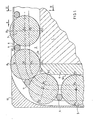
- the running shoe comprises a body or support 1 in the two opposite longitudinal faces of which are formed rectilinear recesses 2 of rectangular section.
- Cylindrical rollers 3 are arranged in the recesses 2 which extend over the entire length of the body.
- the recess 2 has a depth slightly less than the diameter of the rollers 3 so that the rollers therein project from the body; its width is substantially equal to the length of the rollers, the latter being thus guided laterally with precision.
- cylindrical needles 4 which are longer than the rollers and the ends of which are engaged in recesses 5 arranged laterally, on either side of the recesses 2.
- These needles which hold the rollers 3 in place are themselves held by flat strips 6 which cover their ends and are partially housed in recesses 7 adjacent to the recesses 5, the depth of these recesses being at least equal to the thickness of the strips; the latter are fixed to the frame 1 by screws 8, by welding, by embedding or by any other means.
- each end of the body 1 is a nozzle 9 closed by a cover 10, these two elements being fixed to the body 1 by bolts not shown.
- Each of the internal lateral faces of the end piece 9 has a recess 11, the bottom of which is connected to the internal faces of the strips 6; its central part 12 is connected to the bottoms of the recesses 2 by externally cylindrical portions 12a.
- the body 1, your tips 9 and the covers 10 determine an endless path for the rollers 3 and for the holding needles 4.
- each of the rollers passes successively in the upper recess 2, inside one of the end pieces, in the lower recess 2 and inside the other end piece; the bottoms of the recesses 2 and the faces 12 of the end pieces constitute rolling tracks for these rollers.
- the holding needles 4 move successively in contact with the upper bands 6, then from the bottom of the recess 11 of one of the end pieces, lower bands 6 and the bottom of the recess 11 of the other end piece, these bands and these recesses constituting raceways for the needles.
- the bands 6 are parallel to the bottom of the recesses 2, except at their ends. These bands begin to bend practically from the point of tangency M of the needle 4 adjacent to the roller 3 when the latter is at the end A 1 of the straight part of the track 2a or 2b (see Figure 1 ).
- the clearances between the different rollers located in the straight parts are therefore constant and have the same value j.
- the recesses 11 are not parallel to the track 12-12a, they are shaped with respect to this track so as to bring the needles 4 into a position such that the distance between the axes of symmetry 0 1 and 0 2 of the adjacent rollers is found in the end pieces remains identical when measured on the geometric path of the axis.
- the shape of the recesses 11 could be such as the distance between the contact generators A 1 and A 2 measured on the arc 12a, the distance between the generators B 1 and B 2 diametrically opposite to the generators A 1 and A 2 , or between two axes respectively between A 1 and B, and between A 2 and B 2 and located at the same distance from the arc 12a which remains constant.
- the path 11 has been determined by the conditions that the roller follows an imposed path A 3 A, A 24 A and that its axis of symmetry O 3 , 0 1 , 0 2 or 0 4 remains equidistant of those of the rollers which are adjacent to it, when this distance is measured on the geometrical course of these axes.
- An advantageous position of the homologous axes can be mathematically determined a little below the axis of symmetry and such that the rollers remain practically contiguous in the straight parts and still very close in the curved parts, the equidistance of the homologous axes always measured according to their geometric shape, being ensured by the conformation of the path 11, thus obliging the rollers to respect the same speed as soon as they are on the straight tracks.
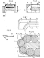
- the pads can be straight; but they can also be curved, as shown in Figure 4 in which the intermediate elements 4 constituted as needles, are held by an element 14. Also in this case, the shape of the element 14 is determined so that the distance between the axes of two adjacent rollers 3 remains constant, if we measure it on the curved path that these axes travel.
- the tip 9 and its cover 10 are replaced by a tip 19 which, in one or more parts, has extensions 19a, of U or L section for example, adjacent to the recess 2a of the body 1 of the shoe and the lower faces of which form continuous tracks for the needles 4.
- the extensions 19a of the two end pieces meet substantially in the middle of the shoe. It is also conceivable that the end pieces of each end and their extension above the body of the skate make only one and the same part, the mounting of the rolling elements being effected by the other face of the body of the skate.
- each of the lateral elements 9a has an extension 9d which extends above the body 1 and the lower face of which extends the bottom of the recess 13 up to the lower face of the retaining strip 6a, the latter being here shorter than the body 1.
- the extensions 9d of the end pieces may preferably be stopped at the place 24 where the intermediate member is positioned when the carrier roller which immediately precedes it is on the point to leave the straight track of the skate body. Indeed, it is useful to provide, at the connection of the track of the body of the skate with the cylindrical part of the end piece, a chamfer 23 intended to facilitate the introduction of the carrier roller under the load. At this precise point any constraint is removed on the intermediate member which will therefore easily cross the passage from one track to another.
- the strips 21 will be stopped, preferably, at the place 22 where the intermediate member is positioned when the carrier roller immediately following it leaves the straight track.
- This slight chamfer 23 in fact eliminates at this precise point from the course any constraint on the intermediate member which will thus be able to pass easily from the track formed by the extension to that formed in the end piece.
Landscapes
- Engineering & Computer Science (AREA)
- General Engineering & Computer Science (AREA)
- Mechanical Engineering (AREA)
- Footwear And Its Accessory, Manufacturing Method And Apparatuses (AREA)
Applications Claiming Priority (2)
| Application Number | Priority Date | Filing Date | Title |
|---|---|---|---|
| FR8118912 | 1981-10-02 | ||
| FR8118912A FR2514088A1 (fr) | 1981-10-02 | 1981-10-02 | Patin de roulement |
Publications (2)
| Publication Number | Publication Date |
|---|---|
| EP0076754A1 EP0076754A1 (fr) | 1983-04-13 |
| EP0076754B1 true EP0076754B1 (fr) | 1986-12-17 |
Family
ID=9262840
Family Applications (1)
| Application Number | Title | Priority Date | Filing Date |
|---|---|---|---|
| EP19820401789 Expired EP0076754B1 (fr) | 1981-10-02 | 1982-09-30 | Patin de roulement |
Country Status (3)
| Country | Link |
|---|---|
| EP (1) | EP0076754B1 (enExample) |
| DE (1) | DE3274753D1 (enExample) |
| FR (1) | FR2514088A1 (enExample) |
Families Citing this family (8)
| Publication number | Priority date | Publication date | Assignee | Title |
|---|---|---|---|---|
| EP0296538A1 (fr) * | 1987-06-26 | 1988-12-28 | Egis S.A. | Dispositif à roulement pour le guidage de pièces mobiles à mouvement linéaire |
| DE4103672C2 (de) * | 1991-02-07 | 1998-11-26 | Schaeffler Waelzlager Ohg | Käfig zur Führung der Wälzkörper eines Umlaufschuhs für eine Linearführung |
| JPH09296821A (ja) * | 1996-05-07 | 1997-11-18 | Thk Kk | 直線案内装置のスライダの製造方法 |
| IT1292868B1 (it) * | 1997-04-17 | 1999-02-11 | Lazzari Srl | Pattino di scorrimento a circolazione di sfere |
| US6243369B1 (en) | 1998-05-06 | 2001-06-05 | Terayon Communication Systems, Inc. | Apparatus and method for synchronizing an SCDMA upstream or any other type upstream to an MCNS downstream or any other type downstream with a different clock rate than the upstream |
| US6364086B1 (en) | 1998-05-29 | 2002-04-02 | Rexroth Star Gmbh | Chain of rolling elements chain arrangement |
| DE20101760U1 (de) | 2001-02-01 | 2002-06-13 | Rexroth Star Gmbh | Wälzkörperkette |
| US11545380B2 (en) * | 2018-11-01 | 2023-01-03 | Brooks Automation Us Llc | Transport apparatus with linear bearing |
Family Cites Families (4)
| Publication number | Priority date | Publication date | Assignee | Title |
|---|---|---|---|---|
| US3567295A (en) * | 1968-09-24 | 1971-03-02 | Rolamite Technology Inc | Linear recirculating roller bearing |
| DE2416198A1 (de) * | 1974-04-03 | 1975-10-16 | Schaeffler Ohg Industriewerk | Waelzlager zur laengsbeweglichen lagerung eines teiles mit ebener laufflaeche |
| CH606849A5 (en) * | 1976-08-24 | 1978-11-15 | Schneeberger Ag W | Bearing block with recirculating combined balls and rollers |
| CH611393A5 (en) * | 1976-10-27 | 1979-05-31 | Schneeberger Ag W | Circulating rolling-contact-element bearing |
-
1981
- 1981-10-02 FR FR8118912A patent/FR2514088A1/fr active Granted
-
1982
- 1982-09-30 DE DE8282401789T patent/DE3274753D1/de not_active Expired
- 1982-09-30 EP EP19820401789 patent/EP0076754B1/fr not_active Expired
Also Published As
| Publication number | Publication date |
|---|---|
| FR2514088A1 (fr) | 1983-04-08 |
| DE3274753D1 (en) | 1987-01-29 |
| EP0076754A1 (fr) | 1983-04-13 |
| FR2514088B1 (enExample) | 1983-12-23 |
Similar Documents
| Publication | Publication Date | Title |
|---|---|---|
| EP2440481B1 (fr) | Installation de convoyage comprenant au moins un couloir courbe | |
| EP0076754B1 (fr) | Patin de roulement | |
| FR2522764A1 (fr) | Convertisseur de mouvement de rotation en mouvement lineaire a billes et mecanisme d'avance utilisant un tel convertisseur | |
| FR2635508A1 (fr) | Transporteur accumulateur sans fin a voies superieure et inferieure | |
| FR2705941A1 (fr) | Ensemble de pignons pour bicyclettes. | |
| FR2476251A1 (fr) | Dispositif d'articulation a tourillonnement et a coulissement d'une piece sur un arbre | |
| FR2521664A1 (fr) | Palier lineaire sans fin a billes et unite de palier incluant de tels paliers | |
| CA1316802C (fr) | Chemin de roulement pour dispositif antiderapant | |
| FR2521666A1 (fr) | Accouplement cannele a coulissement illimite | |
| FR2639082A1 (fr) | Vis a billes comportant une tige filetee soutenue par des montants et un ecrou deplacable sur toute la longueur de la tige | |
| FR2513492A1 (fr) | Dispositif pour le retournement d'objets en forme de tiges tels qu'en particulier des cigarettes | |
| EP0474948A1 (fr) | Dispositif de guidage linéaire | |
| FR2561332A1 (fr) | Ensemble de palier a billes avec guidage lineaire | |
| FR2818295A1 (fr) | Dispositif de tirage en continu pour machine a tricoter | |
| FR2545892A1 (fr) | Palier lineaire a glissement | |
| FR3009049A1 (fr) | Disque d'embrayage pour embrayage a friction | |
| FR2479371A1 (fr) | Roulement perfectionne pour mouvements longitudinaux | |
| FR2574056A1 (fr) | Circuit de chaines a pinces etireuses montees sur galets pour machine a etirer une matiere en bandes | |
| FR2579699A1 (fr) | Roulement a billes pour mouvements longitudinaux entre un arbre et un corps de palier | |
| EP3999322B1 (fr) | Dispositif d'entrainement avec friction réduite | |
| FR3009048A1 (fr) | Disque d'embrayage pour embrayage a friction | |
| FR2590946A1 (fr) | Roulement a billes lineaire pour chariot de machine-outil ou analogue | |
| FR2786108A1 (fr) | Ski | |
| FR2535237A1 (fr) | Procede de rectification des chemins de roulement d'une piece en u et glissiere a billes utilisant une telle piece, notamment pour machines-outils | |
| FR2504998A1 (fr) | Patin de roulement |
Legal Events
| Date | Code | Title | Description |
|---|---|---|---|
| PUAI | Public reference made under article 153(3) epc to a published international application that has entered the european phase |
Free format text: ORIGINAL CODE: 0009012 |
|
| AK | Designated contracting states |
Designated state(s): CH DE FR GB IT LI |
|
| 17P | Request for examination filed |
Effective date: 19830705 |
|
| GRAA | (expected) grant |
Free format text: ORIGINAL CODE: 0009210 |
|
| ITF | It: translation for a ep patent filed | ||
| AK | Designated contracting states |
Kind code of ref document: B1 Designated state(s): CH DE FR GB IT LI |
|
| REF | Corresponds to: |
Ref document number: 3274753 Country of ref document: DE Date of ref document: 19870129 |
|
| PLBE | No opposition filed within time limit |
Free format text: ORIGINAL CODE: 0009261 |
|
| STAA | Information on the status of an ep patent application or granted ep patent |
Free format text: STATUS: NO OPPOSITION FILED WITHIN TIME LIMIT |
|
| 26N | No opposition filed | ||
| PGFP | Annual fee paid to national office [announced via postgrant information from national office to epo] |
Ref country code: FR Payment date: 19890926 Year of fee payment: 8 |
|
| PG25 | Lapsed in a contracting state [announced via postgrant information from national office to epo] |
Ref country code: LI Effective date: 19890930 Ref country code: GB Effective date: 19890930 Ref country code: CH Effective date: 19890930 |
|
| GBPC | Gb: european patent ceased through non-payment of renewal fee | ||
| REG | Reference to a national code |
Ref country code: CH Ref legal event code: PL |
|
| PG25 | Lapsed in a contracting state [announced via postgrant information from national office to epo] |
Ref country code: DE Effective date: 19900601 |
|
| PG25 | Lapsed in a contracting state [announced via postgrant information from national office to epo] |
Ref country code: FR Effective date: 19910530 |
|
| REG | Reference to a national code |
Ref country code: FR Ref legal event code: ST |