EP0076659B1 - A vacuum interrupter - Google Patents
A vacuum interrupter Download PDFInfo
- Publication number
- EP0076659B1 EP0076659B1 EP82305230A EP82305230A EP0076659B1 EP 0076659 B1 EP0076659 B1 EP 0076659B1 EP 82305230 A EP82305230 A EP 82305230A EP 82305230 A EP82305230 A EP 82305230A EP 0076659 B1 EP0076659 B1 EP 0076659B1
- Authority
- EP
- European Patent Office
- Prior art keywords
- electrode
- arc
- vacuum interrupter
- contact
- copper
- Prior art date
- Legal status (The legal status is an assumption and is not a legal conclusion. Google has not performed a legal analysis and makes no representation as to the accuracy of the status listed.)
- Expired
Links
Images


Classifications
-
- H—ELECTRICITY
- H01—ELECTRIC ELEMENTS
- H01H—ELECTRIC SWITCHES; RELAYS; SELECTORS; EMERGENCY PROTECTIVE DEVICES
- H01H33/00—High-tension or heavy-current switches with arc-extinguishing or arc-preventing means
- H01H33/60—Switches wherein the means for extinguishing or preventing the arc do not include separate means for obtaining or increasing flow of arc-extinguishing fluid
- H01H33/66—Vacuum switches
-
- H—ELECTRICITY
- H01—ELECTRIC ELEMENTS
- H01H—ELECTRIC SWITCHES; RELAYS; SELECTORS; EMERGENCY PROTECTIVE DEVICES
- H01H1/00—Contacts
- H01H1/02—Contacts characterised by the material thereof
- H01H1/0203—Contacts characterised by the material thereof specially adapted for vacuum switches
Definitions
- the present invention relates to a vacuum interrupter, and more specifically to an electrode for a vacuum interrupter, which serves to prevent a generation of a switching surge caused by multi-reignition and three-phase simultaneous breaking associated with the multi-reignition (it will, hereinafter, be abbreviated to three-phase simultaneous breaking).
- electrodes of a vacuum interrupter should meet the following conditions:
- the surge by three-phase simultaneous breaking is a phenomenon in which multi-reignition caused in one of the three phases of the commercial frequency current causes high-frequency current to flow through the inter-phase impedance to the other two phases, so that the high-frequency current offsets the commercial frequency current of the other two phases, consequently a current zero point occurs in at least one of the two phases and/or current zero points occur at the two phases, so that the three-phase commercial frequency current is interrupted simultaneously at the three phases thereof.
- this surge is extremely large and in addition to that caused by chopping current larger than the chopping current of the vacuum interrupter, or commercial frequency current at their crest value.
- a surge suppressor or absorber is provided for protecting the electric circuit within switchgear comprising a vacuum interrupter.
- the switchgear of the prior art is large in the'size thereof, reliability for protecting the electric circuit of the electric apparatus provided with the switchgear is low, and its manufacturing cost increases.
- an electrode proper of a vacuum interrupter is desired to prevent surge by multi-reignition and three-phase simultaneous breaking.
- DE-A-2 240 493 discloses an alloy as contact material for a vacuum interrupter, which alloy consists of three metal constituents including chromium.
- GB-A-2 066 293 discloses a copper- chromium based product for a contact for a vacuum interrupter.
- the alloying melt is degassed, deoxidised and optionally alloyed with further elements and is atomised. Subsequently the powder of this alloy is pressed and sintered and optionally impregnated so as to form a contact blank.
- US-A-2 154 700 discloses an electrical contacting element composed substantially of chromium and containing from an appreciable amount up to 10% tin. The tin is used to form a tenacious combination with the chromium.
- US-A-3 821505 discloses a vacuum interrupter comprising two contacts having cooperating contact-making parts each of which is constituted by a porous matrix of metal particles comprising chromium containing from 0.5 percent to 13.5 percent by weight carbon metallurgically bonded together by compacting and heating under high vacuum, the interstices of the matrix being infiltrated under high vacuum with a metal which comprises copper or a copper alloy, and the infiltrated metal constituting between 10 percent and 40 percent of the volume of the infiltrated matrix.
- a primary object of the present invention is to provide a novel vacuum interrupter of which the electrode proper is able to prevent the harmful surging voltage by the multi-reignition and the three phase simultaneous breaking without omission of the other good characteristics of an electrode required for the vacuum interrupter.
- the present invention provides a vacuum interrupter comprising a pair of electrodes having respective contact portions which can contact against or separate from each other within a hermetically and electrically insulating vacuum vessel, with at least one of said contact portions of said vacuum interrupter electrodes made of sintered metal derived from chromium powder and copper or silver characterized by more than 90% by weight chromium powder and less than 10% by weight copper or silver.
- switchgear comprising a vacuum interrupter requires no surge absorber and the like therein. Hence, it is possible to reduce the whole size of the switchgear and its manufacturing cost, and improve reliability for protecting an electric circuit.
- Fig. 1 illustrates a vacuum interrupter comprising two cylindrical insulating housings 1 and 1a made of glass or ceramics. Each open end of the insulating housing 1 or 1 a is provided with a sealing metallic member 2 or 2a.
- the insulating housings 1 and 1a are hermetically connected with each other at the open ends thereof in such a manner that the sealing metallic members 2a are inserted with a metallic shield supporting member 11 therebetween.
- the hermetically sealing metallic members 2 are connected hermetically to the metallic circular end plates 3 and 3a at the other open ends of the housings.
- the above described elements constitute the highly evacuatable vacuum vessel 4.
- a stationary electrode rod 5 is provided hermetically by brazing at the central portion of the end plate 3.
- a stationary electrode 5a is secured to the inside end of the rod 5 positioned within the vacuum vessel 4.
- a movable electrode rod 6 is provided hermetically via a bellows 7 at the central portion of the end plate 3a.
- a movable electrode 6a is secured to the inside end of the rod 6 positioned within the vacuum vessel 4.
- the movable electrode rod 6 and the end plate 3a are interconnected hermetically by means of the bellows 7 mounted therebetween so that the movable electrode 6a is able to close or open against the stationary electrode 5a.
- an axial shield 8 is provided for the stationary electrode rod 5 to protect the inner surface of the housing 1 from attachment of metallic vapor.
- a bellows shield 9 is provided for the movable electrode rod 6 concentric with the outer side of the bellows 7 to protect the bellows outer surface and the inner surface of housing 1a from attachment of metallic vapor.
- the axial shield 8, the bellows shield 9, and the electrodes 5a and 6a are enclosed with a main shield 10 shaped in form of substantially circular cylinder.
- the shield 10 is supported by means of said metallic shield supporting member 11 secured to the center portion on the periphery thereof.
- the arc electrode 12 has a diameter properly larger than that of the electrode rod 5 or 6, and also, is divided by means of a plurality of slits 14 into a plurality of pedals 12a.
- the slits 14 penetrate the arc electrode 12 axially (vertically in Fig. 2) and an arc, when contacts 13, 13 are opened, is driven outward from contacts 13, 13 to the arc electrodes 12, 12 under the lateral magnetic field effected by current flowing through each contact 13, and in turn along the slits 14 to the periphery of the arc electrodes 12, 12.
- At least one contact 13 of the electrodes 5a and 6a is made of a metallic material of mean vapor pressure, the boiling points of such materials are 2700 to 3300 K, while at least one of arc electrodes 12 of the electrodes 5a and 6a is made of a metallic material which transfers easily the arc between the contacts 13, 13 to the pedal 12a of each arc electrode 12 and which is of substantially same as or slightly higher vapor pressure than that of the contact 13.
- a metallic material of mean vapor pressure for the contact 13 chromium, chromium alloy including smaller content than 10% by weight copper, or chromium alloy including smaller content than 10% by weight silver is employed.
- Such chromium alloy may be produced in such a manner that metal powders of chromium, and copper or silver are sintered together under vacuum or inert gas. Alternatively, it may be produced in such a manner that chromium. powder is sintered into porous chromium matrix in which copper or silver having a lower melting point than that of chromium is infiltrated.
- Iron alloy including copper or silver may be produced by sintering together metal powders of copper or silver, and stainless steel under vacuum.
- the iron alloy may be produced in such a manner that metal powder above-described.
- the results of the tests were as follows in the Table 1 below-mentioned.
- each value is a mean of three testpieces. Especially, each contact electric resistance includes that of each electrode rod).
- iron and iron alloy for example, iron or stainless steel has a lower chopping value compared with another material, for example, titanium or copper, an ordinary commercial frequency breaking current value, a lower high-frequency breaking current value compared with copper, bad anti-welding characteristics, and a larger contact electric resistance compared with chromium or copper.
- the iron and iron alloy above-mentioned are, therefore, not suitable as a metallic material for the contact 13.
- chromium has the good characteristics of the electrode material, especially, a metallic material for the contact 13, but not a large high-frequency breaking current value as much as copper.
- the switching surge test was performed on the vacuum interrupter comprising electrode assemblies of the above various metallic materials, under a reactor load.
- the switching surge test disclosed the fact that iron, stainless steel, chromium, and chromium alloy including no more than 20% by weight copper or silver were employed as a metallic material for the contact 13, harmful surge voltage was not caused, since accidental occurrence of reignition did not cause multi-reignition and three-phase simultaneous breaking.
- chromium alloy included copper or silver within the range of 10% to 20% by weight, the alloy had poor anti-welding characteristics, and increased chopping current i.e. chopping surge voltage.
- the metallic material which had substantially the same, or slightly higher vapor pressure than that of the metallic material for the contact 13, and good transferability of arc between the contacts 13,13 to the arc electrode 12 was most preferably employed as the material for the arc electrode 12 in relation to the above-mentioned material for the contact 13.
- the metallic material for the arc electrode which has slightly higher vapor pressure than that of the material for the contact 13 might be a copper alloy, an iron alloy or stainless steel alloy, which did not include metallic material of low vapor pressure, for example, molybdenum or tungsten to a large extent of low vapor pressure material.
- Fig. 3 illustrates another embodiment 12 of an arc electrode, which is divided by a plurality of slits 14b into a plurality of pedals 12b.
- the slits 14a extends through a thickness of the arc electrode 12, inclined to the axis and radius of the arc electrode 12, so that the adjacent pedals 12b are positioned above one another in the axial direction of the arc electrode 12.
- the present vacuum interrupter comprises a disk-shaped electrode 15 which is provided via a high electric resistance spacer 22 (shown in Fig. 6) at the inside ends of electrode rods 5 and 6 respectively.
- Longitudinal magnetic field generating coil electrode 27, which has substantially the same diameter to that of the electrode 15, is mounted respectively on the electrode rods 5 and 6 behind the electrode 15.
- Each coil electrode 27 converts longitudinal electric current (vertically in Fig. 4) flowing in each electrode rod 5 or 6 into loop current along a periphery in the backside of each electrode 15 to generate the longitudinal magnetic field parallel to the arc.
- the vacuum interrupter of Fig. 4 has capacity to interrupt large electric current.
- a 1/3 turn type of longitudinal magnetic field generating coil electrode 27 is illustrated in Figs. 5 and 6.
- the 1/3 turn type coil electrode 27 .comprises a columnar central conductor 16 having a smaller diameter than that of the electrode rod 6, three first circular-arc-shaped coil sections 17a, 17b and 17c positioned concentrically around the central conductor 16, three first arm sections 18a, 18b and 18c extending outward from trisections of the periphery of the central conductor 16 through each space of the first coil sections 17a, 17b and 17c, three second circular-arc-shaped coil sections 19a, 19b and 19c extending from the ends of the first arms 18a, 18b and 18c concentrically to the first coil sections 17a, 17b and 17c, and three second arm sections 20a, 20b and 20c extending in parallel, respectively, to the three first arm sections 18a, 18b and 18c in the identified plane, and interconnecting respectively the second coil sections 19a, 19b and 19c to the first coil sections 17a, 17b and 17c
- the coil electrode 27 is connected electrically and mechanically to the electrode rod 6 at the first coil sections 17a, 17b and 17c, and electrically and mechanically to the electrode 15 at the central conductor 16.
- the second coil sections 19a, 19b and 19c of the coil electrode 27 are supported by means of a ceramics or high electric resistance metallic disk-shaped coil electrode support 23 mounted on the electrode rod 6.
- the central conductor 16 is mechanically connected to the electrode rod 6, via a ceramics or high electric resistance metallic hollow cylindrical spacer 22.
- the electric resistance spacer 22 is positioned in a bore 21 defined at the inside end of the electrode rod 6.
- a gas exhausting hole is indicated at a numeral 24 in Fig. 6.
- the hole 24 is provided for brazing the electric resistance spacer 22 to the electrode rod 6.
- the electrode 15 of Fig. 6 is made of the same material as that of the contact 13 of Figs. 1 to 3.
- Fig. 7 illustrates another embodiment of the electrode 15 of Fig. 6 in which a circular-plate-shaped contact 25 is connected to a disk shaped arc electrode 26 by brazing and projects from the central opening of the disk shaped arc electrode 26.
- the contact 25 is made of the same metallic material as the contact 13 of Figs. 1 to 3, and electrically and mechanically connected to the central conductor 16 by brazing through a thickness of the arc electrode 26.
- the arc electrode 26 is made of the same metallic material as the arc electrode 12 of Figs. 1 to 3.
- the electrode 28 by the embodiment of Fig. 7 can perform electric arc breaking by means of the contacts 25 within a low electric current range, and within a high electric current range, in such a manner that the magnetic field generated by the coil electrode 27 scatters the arc on the surface of the arc electrode 26.
Landscapes
- High-Tension Arc-Extinguishing Switches Without Spraying Means (AREA)
Description
- The present invention relates to a vacuum interrupter, and more specifically to an electrode for a vacuum interrupter, which serves to prevent a generation of a switching surge caused by multi-reignition and three-phase simultaneous breaking associated with the multi-reignition (it will, hereinafter, be abbreviated to three-phase simultaneous breaking).
- Generally, electrodes of a vacuum interrupter (Patent Specifications, for example, US-A-3,818,163 and US-A-3,960,554) should meet the following conditions:
- (1) to have high static withstanding voltage
- (2) to have large electric current breaking capacity
- (3) to have large electric current flowing capacity
- (4) to be easily separable without welding together of the contact surfaces
- (5) to withstand the overvoltage caused in the switching surge, and
- (6) to have long electric and mechanical endurance.
- Recently, research of a switching surge mechanism has been developed, which has revealed the fact that the switching surge includes surges caused by multi-reignition and three-phase simultaneous breaking besides the known surges by current chopping and reignition.
- Surges caused by multi-reignition are a phenomenon in which ignitions and extinctions of arc alternate as a result of the competition between the interelectrode dielectric strength recovered by the current breaking operation of a vacuum interrupter and the recovery voltage appearing in the interelectrode immediately after the current breaking, and thus, the interelectrode voltage increases gradually with time.
- Such surge is caused in the following cases:
- (1) high-frequency arc extinction where the high-frequency (commercial frequency to 1000 KHz, for example 200 KHz) current flowing through the electric circuit is broken at its zero point, (2) when current chopping happens in an insufficient arcing time, (3) where after the contacts are separated in the before vicinity of a zero point of the commercial frequency current, the arc extinction takes place immediately nearest a current zero point.
- The surge by three-phase simultaneous breaking is a phenomenon in which multi-reignition caused in one of the three phases of the commercial frequency current causes high-frequency current to flow through the inter-phase impedance to the other two phases, so that the high-frequency current offsets the commercial frequency current of the other two phases, consequently a current zero point occurs in at least one of the two phases and/or current zero points occur at the two phases, so that the three-phase commercial frequency current is interrupted simultaneously at the three phases thereof.
- Also, this surge is extremely large and in addition to that caused by chopping current larger than the chopping current of the vacuum interrupter, or commercial frequency current at their crest value.
- Since electrodes of vacuum interrupters which are made of metallic contact materials for vacuum interrupters commercially applied at present have, in themselves, no capacity to protect the electric circuit from surges by multi-reignition and three-phase simultaneous breaking, a surge suppressor or absorber is provided for protecting the electric circuit within switchgear comprising a vacuum interrupter.
- Therefore, the switchgear of the prior art is large in the'size thereof, reliability for protecting the electric circuit of the electric apparatus provided with the switchgear is low, and its manufacturing cost increases. In order to solve such problems, an electrode proper of a vacuum interrupter is desired to prevent surge by multi-reignition and three-phase simultaneous breaking.
- DE-A-2 240 493 discloses an alloy as contact material for a vacuum interrupter, which alloy consists of three metal constituents including chromium.
- GB-A-2 066 293 discloses a copper- chromium based product for a contact for a vacuum interrupter. The alloying melt is degassed, deoxidised and optionally alloyed with further elements and is atomised. Subsequently the powder of this alloy is pressed and sintered and optionally impregnated so as to form a contact blank.
- US-A-2 154 700 discloses an electrical contacting element composed substantially of chromium and containing from an appreciable amount up to 10% tin. The tin is used to form a tenacious combination with the chromium.
- US-A-3 821505 discloses a vacuum interrupter comprising two contacts having cooperating contact-making parts each of which is constituted by a porous matrix of metal particles comprising chromium containing from 0.5 percent to 13.5 percent by weight carbon metallurgically bonded together by compacting and heating under high vacuum, the interstices of the matrix being infiltrated under high vacuum with a metal which comprises copper or a copper alloy, and the infiltrated metal constituting between 10 percent and 40 percent of the volume of the infiltrated matrix.
- A primary object of the present invention is to provide a novel vacuum interrupter of which the electrode proper is able to prevent the harmful surging voltage by the multi-reignition and the three phase simultaneous breaking without omission of the other good characteristics of an electrode required for the vacuum interrupter.
- The present invention provides a vacuum interrupter comprising a pair of electrodes having respective contact portions which can contact against or separate from each other within a hermetically and electrically insulating vacuum vessel, with at least one of said contact portions of said vacuum interrupter electrodes made of sintered metal derived from chromium powder and copper or silver characterized by more than 90% by weight chromium powder and less than 10% by weight copper or silver.
- In accordance with the present invention, since the nature of the electrode materials proper prevent generating of surges by multi-reignition and three-phase simultaneous breaking, switchgear comprising a vacuum interrupter requires no surge absorber and the like therein. Hence, it is possible to reduce the whole size of the switchgear and its manufacturing cost, and improve reliability for protecting an electric circuit.
- Ways of carrying out the invention are described in detail below with reference to drawings which illustrate several specific embodiments, in which:-
- Fig. 1 is a longitudinal cross-sectional view of a vacuum interrupter according to the present invention;
- Fig. 2 is an enlarged perspective view of the electrode of Fig. 1;
- Fig. 3 is an enlarged perspective view of another electrode embodying the present invention;
- Fig. 4 is a longitudinal cross-sectional view of a vacuum interrupter embodying the present invention;
- Fig. 5 is a plan view of a coil electrode of Fig. 4;
- Fig. 6 is a longitudinal cross-sectional view of an electrode assembly of Fig. 4;
- Fig. 7 is a longitudinal cross-sectional view of another embodiment of the electrode assembly of Fig. 4.
- Fig. 1 illustrates a vacuum interrupter comprising two cylindrical
insulating housings 1 and 1a made of glass or ceramics. Each open end of theinsulating housing 1 or 1 a is provided with a sealingmetallic member 2 or 2a. Theinsulating housings 1 and 1a are hermetically connected with each other at the open ends thereof in such a manner that the sealing metallic members 2a are inserted with a metallicshield supporting member 11 therebetween. Also, the hermetically sealingmetallic members 2 are connected hermetically to the metalliccircular end plates 3 and 3a at the other open ends of the housings. The above described elements constitute the highlyevacuatable vacuum vessel 4. - A
stationary electrode rod 5 is provided hermetically by brazing at the central portion of theend plate 3. A stationary electrode 5a is secured to the inside end of therod 5 positioned within thevacuum vessel 4. Also, amovable electrode rod 6 is provided hermetically via abellows 7 at the central portion of the end plate 3a. Amovable electrode 6a is secured to the inside end of therod 6 positioned within thevacuum vessel 4. Themovable electrode rod 6 and the end plate 3a are interconnected hermetically by means of thebellows 7 mounted therebetween so that themovable electrode 6a is able to close or open against the stationary electrode 5a. - Within the
vacuum vessel 4, an axial shield 8 is provided for thestationary electrode rod 5 to protect the inner surface of thehousing 1 from attachment of metallic vapor. A bellows shield 9 is provided for themovable electrode rod 6 concentric with the outer side of thebellows 7 to protect the bellows outer surface and the inner surface of housing 1a from attachment of metallic vapor. Also, the axial shield 8, the bellows shield 9, and theelectrodes 5a and 6a are enclosed with amain shield 10 shaped in form of substantially circular cylinder. Theshield 10 is supported by means of said metallicshield supporting member 11 secured to the center portion on the periphery thereof. - The stationary and
movable electrodes 5a and 6a of so-called inductive magnetic driving type shown in Fig. 2, each comprise a disk-shaped arc electrode 12 and a ring or button-shaped contact 13 projecting from the central portion of the surface of thearc electrode 12. - The
arc electrode 12 has a diameter properly larger than that of theelectrode rod slits 14 into a plurality ofpedals 12a. Theslits 14 penetrate thearc electrode 12 axially (vertically in Fig. 2) and an arc, whencontacts contacts arc electrodes contact 13, and in turn along theslits 14 to the periphery of thearc electrodes - At least one
contact 13 of theelectrodes 5a and 6a is made of a metallic material of mean vapor pressure, the boiling points of such materials are 2700 to 3300 K, while at least one ofarc electrodes 12 of theelectrodes 5a and 6a is made of a metallic material which transfers easily the arc between thecontacts pedal 12a of eacharc electrode 12 and which is of substantially same as or slightly higher vapor pressure than that of thecontact 13. As a metallic material of mean vapor pressure for thecontact 13, chromium, chromium alloy including smaller content than 10% by weight copper, or chromium alloy including smaller content than 10% by weight silver is employed. As a metallic material for thearc electrode 12, chromium, chromium alloy including smaller content than 10% by weight copper, chromium alloy including smaller content than 10% by weight silver, copper, iron, iron alloy, for example, stainless steel, or iron alloy including copper or silver. - , Such chromium alloy may be produced in such a manner that metal powders of chromium, and copper or silver are sintered together under vacuum or inert gas. Alternatively, it may be produced in such a manner that chromium. powder is sintered into porous chromium matrix in which copper or silver having a lower melting point than that of chromium is infiltrated.
- Iron alloy including copper or silver may be produced by sintering together metal powders of copper or silver, and stainless steel under vacuum.
- Also, the iron alloy may be produced in such a manner that metal powder above-described. The results of the tests were as follows in the Table 1 below-mentioned.
-
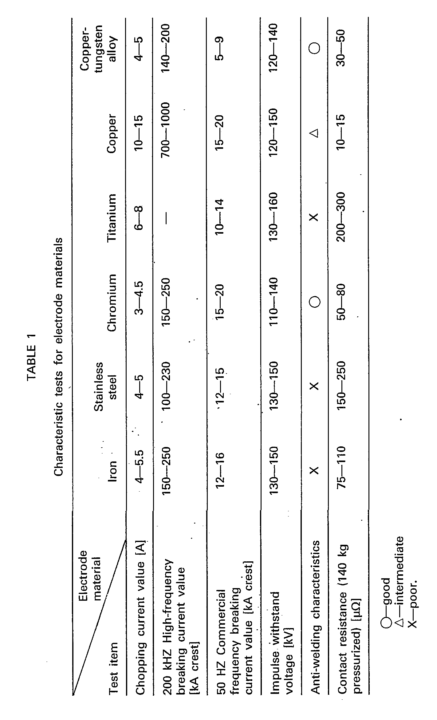
- (Remark: Each value is a mean of three testpieces. Especially, each contact electric resistance includes that of each electrode rod).
- As apparent from the above Table 1, iron and iron alloy for example, iron or stainless steel has a lower chopping value compared with another material, for example, titanium or copper, an ordinary commercial frequency breaking current value, a lower high-frequency breaking current value compared with copper, bad anti-welding characteristics, and a larger contact electric resistance compared with chromium or copper. The iron and iron alloy above-mentioned are, therefore, not suitable as a metallic material for the
contact 13. - Also, as apparent from the Table 1, chromium has the good characteristics of the electrode material, especially, a metallic material for the
contact 13, but not a large high-frequency breaking current value as much as copper. - Next, the arc transferability tests were performed on various combinations of metallic materials for the
contact 13 andarc electrode 12. The results of the tests were as follows in the Table 2 below-mentioned.
- As apparent from the Table 2, combination of metallic materials for the
contact 13 or thearc electrode 12 varies the arc transferability. - Subsequent to the characteristic tests on various metallic materials of an electrode material as above-mentioned, the switching surge test was performed on the vacuum interrupter comprising electrode assemblies of the above various metallic materials, under a reactor load.
- The switching surge test disclosed the fact that iron, stainless steel, chromium, and chromium alloy including no more than 20% by weight copper or silver were employed as a metallic material for the
contact 13, harmful surge voltage was not caused, since accidental occurrence of reignition did not cause multi-reignition and three-phase simultaneous breaking. However, in case chromium alloy included copper or silver within the range of 10% to 20% by weight, the alloy had poor anti-welding characteristics, and increased chopping current i.e. chopping surge voltage. - Consequently, it was found, from the results of the switching surge tests, and the Tables 1 and 2, that chromium, or chromium alloy including smaller content than 10% by weight copper or silver was adapted to constitute the
contact 13, which caused no surges by the multi-reignition and by the three-phase simultaneous breaking, and satisfied the above-mentioned requirements for an electrode of the vacuum interrupter. - Also, it was found, from the results of the switching surge test, and the Tables 1 and 2, that the metallic material which had substantially the same, or slightly higher vapor pressure than that of the metallic material for the
contact 13, and good transferability of arc between thecontacts arc electrode 12 was most preferably employed as the material for thearc electrode 12 in relation to the above-mentioned material for thecontact 13. The metallic material for the arc electrode which has slightly higher vapor pressure than that of the material for thecontact 13 might be a copper alloy, an iron alloy or stainless steel alloy, which did not include metallic material of low vapor pressure, for example, molybdenum or tungsten to a large extent of low vapor pressure material. - Fig. 3 illustrates another
embodiment 12 of an arc electrode, which is divided by a plurality of slits 14b into a plurality ofpedals 12b. The slits 14a extends through a thickness of thearc electrode 12, inclined to the axis and radius of thearc electrode 12, so that theadjacent pedals 12b are positioned above one another in the axial direction of thearc electrode 12. - Now, another embodiment of the vacuum interrupter by the present invention will be described with reference to Fig. 4. Such embodiment is provided with a pair of electrode assemblies comprising a coil electrode producing a longitudinal magnetic field parallel to .the interelectrode arc. The same symbol will be applied to the same portion of the embodiment of Fig. 1, hereinafter. The present vacuum interrupter comprises a disk-shaped
electrode 15 which is provided via a high electric resistance spacer 22 (shown in Fig. 6) at the inside ends ofelectrode rods coil electrode 27, which has substantially the same diameter to that of theelectrode 15, is mounted respectively on theelectrode rods electrode 15. Eachcoil electrode 27 converts longitudinal electric current (vertically in Fig. 4) flowing in eachelectrode rod electrode 15 to generate the longitudinal magnetic field parallel to the arc. Thus, the vacuum interrupter of Fig. 4 has capacity to interrupt large electric current. - A 1/3 turn type of longitudinal magnetic field generating
coil electrode 27 is illustrated in Figs. 5 and 6. The 1/3 turntype coil electrode 27 .comprises a columnarcentral conductor 16 having a smaller diameter than that of theelectrode rod 6, three first circular-arc-shapedcoil sections central conductor 16, threefirst arm sections central conductor 16 through each space of thefirst coil sections coil sections first arms first coil sections second arm sections 20a, 20b and 20c extending in parallel, respectively, to the threefirst arm sections second coil sections first coil sections coil electrode 27 is connected electrically and mechanically to theelectrode rod 6 at thefirst coil sections electrode 15 at thecentral conductor 16. Thesecond coil sections coil electrode 27 are supported by means of a ceramics or high electric resistance metallic disk-shapedcoil electrode support 23 mounted on theelectrode rod 6. Thecentral conductor 16 is mechanically connected to theelectrode rod 6, via a ceramics or high electric resistance metallic hollowcylindrical spacer 22. Theelectric resistance spacer 22 is positioned in abore 21 defined at the inside end of theelectrode rod 6. A gas exhausting hole is indicated at a numeral 24 in Fig. 6. Thehole 24 is provided for brazing theelectric resistance spacer 22 to theelectrode rod 6. - The
electrode 15 of Fig. 6 is made of the same material as that of thecontact 13 of Figs. 1 to 3. - Fig. 7 illustrates another embodiment of the
electrode 15 of Fig. 6 in which a circular-plate-shapedcontact 25 is connected to a disk shapedarc electrode 26 by brazing and projects from the central opening of the disk shapedarc electrode 26. Thecontact 25 is made of the same metallic material as thecontact 13 of Figs. 1 to 3, and electrically and mechanically connected to thecentral conductor 16 by brazing through a thickness of thearc electrode 26. While, thearc electrode 26 is made of the same metallic material as the arc electrode 12 of Figs. 1 to 3. Theelectrode 28 by the embodiment of Fig. 7 can perform electric arc breaking by means of thecontacts 25 within a low electric current range, and within a high electric current range, in such a manner that the magnetic field generated by thecoil electrode 27 scatters the arc on the surface of thearc electrode 26. - The results of the characteristic tests on the vacuum interrupter of Fig. 4 are same to those listed on the Tables 1 and 2.
Claims (6)
Applications Claiming Priority (4)
| Application Number | Priority Date | Filing Date | Title |
|---|---|---|---|
| JP157847/81 | 1981-10-03 | ||
| JP15784781A JPS5873928A (en) | 1981-10-03 | 1981-10-03 | Vacuum breaker |
| JP159903/81 | 1981-10-07 | ||
| JP15990381A JPS5873929A (en) | 1981-10-07 | 1981-10-07 | Vacuum breaker |
Publications (2)
| Publication Number | Publication Date |
|---|---|
| EP0076659A1 EP0076659A1 (en) | 1983-04-13 |
| EP0076659B1 true EP0076659B1 (en) | 1986-07-30 |
Family
ID=26485155
Family Applications (1)
| Application Number | Title | Priority Date | Filing Date |
|---|---|---|---|
| EP82305230A Expired EP0076659B1 (en) | 1981-10-03 | 1982-10-01 | A vacuum interrupter |
Country Status (4)
| Country | Link |
|---|---|
| US (1) | US4471184A (en) |
| EP (1) | EP0076659B1 (en) |
| KR (1) | KR860001452B1 (en) |
| DE (1) | DE3272338D1 (en) |
Families Citing this family (14)
| Publication number | Priority date | Publication date | Assignee | Title |
|---|---|---|---|---|
| CA1230909A (en) * | 1983-03-22 | 1987-12-29 | Kaoru Kitakizaki | Vacuum interrupter electrode with low conductivity magnetic arc rotating portion |
| US4698467A (en) * | 1985-10-24 | 1987-10-06 | Kabushiki Kaisha Toshiba | Electrodes of vacuum switch |
| DE3644453A1 (en) * | 1986-12-24 | 1988-07-07 | Licentia Gmbh | SWITCHING PIECE FOR CIRCUIT BREAKER |
| US4797522A (en) * | 1988-02-11 | 1989-01-10 | Westinghouse Electric Corp. | Vacuum-type circuit interrupter |
| US5120918A (en) * | 1990-11-19 | 1992-06-09 | Westinghouse Electric Corp. | Vacuum circuit interrupter contacts and shields |
| DE69411803T2 (en) * | 1993-04-30 | 1998-12-03 | Kabushiki Kaisha Meidensha, Tokio/Tokyo | Electrode and method of making an electrode material |
| US5697150A (en) * | 1993-07-14 | 1997-12-16 | Hitachi, Ltd. | Method forming an electric contact in a vacuum circuit breaker |
| US5852266A (en) * | 1993-07-14 | 1998-12-22 | Hitachi, Ltd. | Vacuum circuit breaker as well as vacuum valve and electric contact used in same |
| DE102005027268B3 (en) * | 2005-06-08 | 2007-01-04 | Siemens Ag | Contact arrangement for vacuum switch |
| KR101116382B1 (en) * | 2010-10-15 | 2012-03-09 | 엘에스산전 주식회사 | Electromagnetic switching device |
| USD680971S1 (en) * | 2010-12-28 | 2013-04-30 | Japan Ae Power Systems Corporation | Vacuum interrupter |
| WO2018189939A1 (en) * | 2017-04-11 | 2018-10-18 | 三菱電機株式会社 | Vacuum valve and vacuum circuit breaker using same |
| CN111668064B (en) * | 2019-03-05 | 2022-08-30 | 平高集团有限公司 | Vacuum arc-extinguishing chamber contact, vacuum arc-extinguishing chamber and vacuum circuit breaker |
| FR3116938A1 (en) * | 2020-11-30 | 2022-06-03 | Schneider Electric Industries Sas | Improved arc breaking medium voltage vacuum interrupter contact and associated vacuum interrupter |
Family Cites Families (13)
| Publication number | Priority date | Publication date | Assignee | Title |
|---|---|---|---|---|
| US2154700A (en) * | 1936-08-31 | 1939-04-18 | Ruben Samuel | Electrical contacting element |
| FR1480001A (en) * | 1965-05-28 | 1967-07-27 | ||
| FR1506165A (en) * | 1966-01-04 | 1967-12-15 | English Electric Co Ltd | Electric vacuum switch |
| GB1194674A (en) * | 1966-05-27 | 1970-06-10 | English Electric Co Ltd | Vacuum Type Electric Circuit Interrupting Devices |
| US3821505A (en) * | 1972-05-18 | 1974-06-28 | English Electric Co Ltd | Vacuum type electric circuit interrupting devices |
| DE2240493C3 (en) * | 1972-08-17 | 1978-04-27 | Siemens Ag, 1000 Berlin Und 8000 Muenchen | Penetration composite metal as a contact material for vacuum switches and process for its manufacture |
| US3828428A (en) * | 1972-09-25 | 1974-08-13 | Westinghouse Electric Corp | Matrix-type electrodes having braze-penetration barrier |
| US3960554A (en) * | 1974-06-03 | 1976-06-01 | Westinghouse Electric Corporation | Powdered metallurgical process for forming vacuum interrupter contacts |
| US4048117A (en) * | 1974-10-29 | 1977-09-13 | Westinghouse Electric Corporation | Vacuum switch contact materials |
| US4078117A (en) * | 1975-11-13 | 1978-03-07 | Lion Oil Company | Concrete curing composition |
| JPS5816731B2 (en) * | 1977-12-28 | 1983-04-01 | 株式会社明電舎 | Vacuum shield electrode |
| JPS6059691B2 (en) * | 1979-02-23 | 1985-12-26 | 三菱電機株式会社 | Vacuum shield contact and its manufacturing method |
| DD155861A3 (en) * | 1979-12-08 | 1982-07-14 | Hans Bohmeier | METHOD FOR PRODUCING SWITCHES |
-
1982
- 1982-09-29 KR KR8204398A patent/KR860001452B1/en not_active Expired
- 1982-09-30 US US06/432,380 patent/US4471184A/en not_active Expired - Fee Related
- 1982-10-01 DE DE8282305230T patent/DE3272338D1/en not_active Expired
- 1982-10-01 EP EP82305230A patent/EP0076659B1/en not_active Expired
Also Published As
| Publication number | Publication date |
|---|---|
| US4471184A (en) | 1984-09-11 |
| EP0076659A1 (en) | 1983-04-13 |
| KR840001765A (en) | 1984-05-16 |
| DE3272338D1 (en) | 1986-09-04 |
| KR860001452B1 (en) | 1986-09-25 |
Similar Documents
| Publication | Publication Date | Title |
|---|---|---|
| EP0076659B1 (en) | A vacuum interrupter | |
| EP0227973B1 (en) | Contact electrode material for vacuum interrupter and method of manufacturing the same | |
| US5793008A (en) | Vacuum interrupter with arc diffusing contact design | |
| EP0119563B1 (en) | Vaccum interrupter and method of its production | |
| KR930011829B1 (en) | Vacuum breaker | |
| US3769538A (en) | Vacuum arc devices with ferrous electrodes | |
| US3821505A (en) | Vacuum type electric circuit interrupting devices | |
| US4438307A (en) | Electric vacuum switch | |
| KR920006060B1 (en) | Vacuum switch tube | |
| US4551596A (en) | Surge-absorberless vacuum circuit interrupter | |
| US4367382A (en) | Vacuum circuit breaker | |
| CA1230909A (en) | Vacuum interrupter electrode with low conductivity magnetic arc rotating portion | |
| CA1319731C (en) | Vacuum circuit interrupter with axial magnetic arc transfer mechanism | |
| EP0118844A2 (en) | Vacuum switch and method of manufacturing the same | |
| US4501941A (en) | Vacuum interrupter contact material | |
| US4661665A (en) | Vacuum interrupter and method of modifying a vacuum interrupter | |
| CA1111883A (en) | Low voltage vacuum switch with three internal contacts including a center floating contact | |
| US4553003A (en) | Cup type vacuum interrupter contact | |
| KR910001370B1 (en) | Vacuum circuit interrupter | |
| US4135071A (en) | Vacuum circuit interrupter with disc-shaped beryllium contacts | |
| JPS6357897B2 (en) | ||
| EP0178796A2 (en) | Manufacture of vacuum interrupter contacts | |
| JPH0479090B2 (en) | ||
| JPH0479089B2 (en) | ||
| JPH07111856B2 (en) | Vacuum interrupter |
Legal Events
| Date | Code | Title | Description |
|---|---|---|---|
| PUAI | Public reference made under article 153(3) epc to a published international application that has entered the european phase |
Free format text: ORIGINAL CODE: 0009012 |
|
| AK | Designated contracting states |
Designated state(s): CH DE FR GB IT LI NL SE |
|
| 17P | Request for examination filed |
Effective date: 19830921 |
|
| GRAA | (expected) grant |
Free format text: ORIGINAL CODE: 0009210 |
|
| ITF | It: translation for a ep patent filed | ||
| AK | Designated contracting states |
Kind code of ref document: B1 Designated state(s): CH DE FR GB IT LI NL SE |
|
| ET | Fr: translation filed | ||
| REF | Corresponds to: |
Ref document number: 3272338 Country of ref document: DE Date of ref document: 19860904 |
|
| PLBE | No opposition filed within time limit |
Free format text: ORIGINAL CODE: 0009261 |
|
| STAA | Information on the status of an ep patent application or granted ep patent |
Free format text: STATUS: NO OPPOSITION FILED WITHIN TIME LIMIT |
|
| 26N | No opposition filed | ||
| PGFP | Annual fee paid to national office [announced via postgrant information from national office to epo] |
Ref country code: SE Payment date: 19891002 Year of fee payment: 8 |
|
| PGFP | Annual fee paid to national office [announced via postgrant information from national office to epo] |
Ref country code: CH Payment date: 19891019 Year of fee payment: 8 |
|
| ITTA | It: last paid annual fee | ||
| PGFP | Annual fee paid to national office [announced via postgrant information from national office to epo] |
Ref country code: NL Payment date: 19891031 Year of fee payment: 8 Ref country code: GB Payment date: 19891031 Year of fee payment: 8 |
|
| PGFP | Annual fee paid to national office [announced via postgrant information from national office to epo] |
Ref country code: DE Payment date: 19891127 Year of fee payment: 8 |
|
| PGFP | Annual fee paid to national office [announced via postgrant information from national office to epo] |
Ref country code: FR Payment date: 19891130 Year of fee payment: 8 |
|
| PG25 | Lapsed in a contracting state [announced via postgrant information from national office to epo] |
Ref country code: GB Effective date: 19901001 |
|
| PG25 | Lapsed in a contracting state [announced via postgrant information from national office to epo] |
Ref country code: SE Effective date: 19901002 |
|
| PG25 | Lapsed in a contracting state [announced via postgrant information from national office to epo] |
Ref country code: LI Effective date: 19901031 Ref country code: CH Effective date: 19901031 |
|
| PG25 | Lapsed in a contracting state [announced via postgrant information from national office to epo] |
Ref country code: NL Effective date: 19910501 |
|
| GBPC | Gb: european patent ceased through non-payment of renewal fee | ||
| NLV4 | Nl: lapsed or anulled due to non-payment of the annual fee | ||
| PG25 | Lapsed in a contracting state [announced via postgrant information from national office to epo] |
Ref country code: FR Effective date: 19910628 |
|
| REG | Reference to a national code |
Ref country code: CH Ref legal event code: PL |
|
| PG25 | Lapsed in a contracting state [announced via postgrant information from national office to epo] |
Ref country code: DE Effective date: 19910702 |
|
| REG | Reference to a national code |
Ref country code: FR Ref legal event code: ST |
|
| EUG | Se: european patent has lapsed |
Ref document number: 82305230.3 Effective date: 19910603 |