EP0076599A2 - Netzgerät - Google Patents
Netzgerät Download PDFInfo
- Publication number
- EP0076599A2 EP0076599A2 EP82305003A EP82305003A EP0076599A2 EP 0076599 A2 EP0076599 A2 EP 0076599A2 EP 82305003 A EP82305003 A EP 82305003A EP 82305003 A EP82305003 A EP 82305003A EP 0076599 A2 EP0076599 A2 EP 0076599A2
- Authority
- EP
- European Patent Office
- Prior art keywords
- power unit
- zero potential
- circuit
- voltage
- current
- Prior art date
- Legal status (The legal status is an assumption and is not a legal conclusion. Google has not performed a legal analysis and makes no representation as to the accuracy of the status listed.)
- Granted
Links
Images
Classifications
-
- G—PHYSICS
- G05—CONTROLLING; REGULATING
- G05F—SYSTEMS FOR REGULATING ELECTRIC OR MAGNETIC VARIABLES
- G05F1/00—Automatic systems in which deviations of an electric quantity from one or more predetermined values are detected at the output of the system and fed back to a device within the system to restore the detected quantity to its predetermined value or values, i.e. retroactive systems
- G05F1/10—Regulating voltage or current
- G05F1/46—Regulating voltage or current wherein the variable actually regulated by the final control device is DC
- G05F1/618—Regulating voltage or current wherein the variable actually regulated by the final control device is DC using semiconductor devices in series and in parallel with the load as final control devices
-
- G—PHYSICS
- G05—CONTROLLING; REGULATING
- G05F—SYSTEMS FOR REGULATING ELECTRIC OR MAGNETIC VARIABLES
- G05F1/00—Automatic systems in which deviations of an electric quantity from one or more predetermined values are detected at the output of the system and fed back to a device within the system to restore the detected quantity to its predetermined value or values, i.e. retroactive systems
- G05F1/10—Regulating voltage or current
- G05F1/46—Regulating voltage or current wherein the variable actually regulated by the final control device is DC
- G05F1/56—Regulating voltage or current wherein the variable actually regulated by the final control device is DC using semiconductor devices in series with the load as final control devices
- G05F1/577—Regulating voltage or current wherein the variable actually regulated by the final control device is DC using semiconductor devices in series with the load as final control devices for plural loads
- G05F1/585—Regulating voltage or current wherein the variable actually regulated by the final control device is DC using semiconductor devices in series with the load as final control devices for plural loads providing voltages of opposite polarities
Definitions
- the invention relates to power units having two output voltages of opposite polarity and common zero potential which, for connection to an input a.c. voltage, has a rectifier and a linear longitudinal regulator for each output voltage.
- Such a power unit is known from the article "Integrated Voltage Regulator” in Elektroniktechnisch 6/1979,pp.24 to 46.
- Installations which have a central mains supply connected via a transformer to a transmitter with an incorporated power unit and a plurality of remote electronic regulators each having an incorporated power unit.
- a central mains supply connected via a transformer to a transmitter with an incorporated power unit and a plurality of remote electronic regulators each having an incorporated power unit.
- one connection of the secondary winding of the transformer is chosen as the zero potential.
- the secondary winding supplies a voltage serving as an input a.c. voltage U to the transmitter and the regulators.
- the transmitter voltage at an output A of the transmitter is also related to this zero potential.
- the transmitter voltage is applied to inputs E 1 to E 4 of the regulators 3a-d, respectively, and is used for the control thereof.
- a power unit with two output voltages of opposite polarity and common zero potential which, for connection to an input a.c. voltage, has a rectifier and a linear longitudinal regulator for each output voltage, characterized in that a current balancing circuit (4, 5, 6) is arranged between the rectifiers (D1, D2) and the longitudinal regulators (IC1, IC2) and that the line carrying the zero potential (0) is connected to one of the two lines of the input a.c. voltage (iU.
- Power units according to the invention have a balanced current on the zero potential line. As a result, it is possible to use a common neutral conductor which reduces expenditure in connection with the line. It is even possible to connect regulators with a switching behaviour and can be controlled with a d.c. voltage from the remote transmitter, without feedbacks occurring.
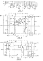
- Fig 2 shows a power unit, to whose input terminals are applied the input a.c. voltage U .
- the lower input terminal in Fig 2 has zero potential and is designated by 0.
- the input a.c. voltage U is rectified by two rectifiers D1 and D2. As the rectifiers have opposite polarity, two voltages occur at the two following capacitors Cl and C2 with different polarities related to the common zero potential. These two voltages are applied by means of low-valued resistors R1 or R2 of a current measuring circuit 4 to in each case one linear longitudinal regulator IC1 or IC2.
- the longitudinal regulators comprise known integrated voltage regulators. Longitudinal regulators IC1 and IC2 are wired to capacitors C3 to C6 in order to prevent undesired oscillations.
- the two output voltages +U A and -U A related to the zero potential
- a comparator circuit 5 To current measuring circuit 4 is connected a comparator circuit 5 and to the latter a current control circuit 6. Together all the three circuits 4, 5 and 6 form a current balancing circuit.
- the current measuring circuit 4 comprises a bridge circuit formed from resistors R3 to R6 and which measures the voltage drop corresponding to the current J 1 or J 2 through resistor Rl or R2. These voltage values reach the comparator circuit 5, which comprises the operational amplifier IC3 and the resistors R7 and R8 at the inverting or non-inverting input, resistor R7 from the non-inverting input to the zero potential 0 and resistor R10 from the output to the inverting input of the operational amplifier IC3.
- the comparison result at the output of the operational amplifier IC3 is a positive or negative voltage value, depending on whether current J 1 or current J 2 preponderates. This voltage value reaches the base of transistor Tl or T2 across a diode D3 or D4.
- the collector of transistor Tl is connected to the input of longitudinal regulator IC1 and its emitter is connected across a resistor R13 to the zero potential.
- a resistor R11 is connected from the base of transistor Tl to zero potential.
- Transistor T2 is connected in the same way with resistors R12 and R14 between the input of longitudinal regulator IC 2 and zero potential.
- the voltages corresponding to currents J 1 and J 2 are determined by the current measuring circuit 4 compared with one another in comparator circuit 5 acting as a proportional controller and a resulting voltage value is supplied to transistor Tl or T2 acting as the control element. Transistor Tl or T2 then carries such a current that, apart from the very small control deviation, currents J 1 and J 2 are the same.
- Fig 3 shows a power unit in which one output voltage +U A is much more highly loaded than the other output voltage -U . Due to the lighter loading, a A circuit comprising a resistor R12 and a Zener diode D6 is used as the longitudinal regulator for this output voltage -U A .
- the input and output connection is the same as the circuit according to Fig 2 and consequently the same references are used for the same parts.
- Zener diode D5 Downstream of capacitor Cl a series connection of a resistor R13 and a Zener diode D5 is connected to zero potential.
- Zener diode D5 has the same Zener voltage as Zener diode D6 and resistors R12 and R13 are identical.
- This power unit also has a current measuring circuit 4', to which is connected a comparator circuit 5'.
- the following current control circuit 6' has only one transistor T3 in series with a resistor Rll connected from the input of longitudinal regulator 7 to zero potential A.
- the addition of the apostrophe means that in principle the circuit with the same reference - numeral is used.
- Transistor 13 is adequate, provided that the output voltage -U A is more lightly loaded than output voltage +U , because then a balancing current A only has to flow in the lightly loaded branch.
- Current J 6 is the same as current J 7 , it being assumed that current J 2 is lower than current J 6 .
- Current J 1 is subject to greater fluctuations and greater loading and consequently so is current J 8 .
- Current J 8 is determined by the current measuring circuit 4' and from this a control signal for transistor T3 is obtained in such a way that current J 5 is the same as current J8.
Landscapes
- Engineering & Computer Science (AREA)
- Physics & Mathematics (AREA)
- Electromagnetism (AREA)
- General Physics & Mathematics (AREA)
- Radar, Positioning & Navigation (AREA)
- Automation & Control Theory (AREA)
- Continuous-Control Power Sources That Use Transistors (AREA)
- Control Of Voltage And Current In General (AREA)
- Pharmaceuticals Containing Other Organic And Inorganic Compounds (AREA)
- Ultra Sonic Daignosis Equipment (AREA)
Applications Claiming Priority (2)
| Application Number | Priority Date | Filing Date | Title |
|---|---|---|---|
| DE3139066 | 1981-10-01 | ||
| DE19813139066 DE3139066A1 (de) | 1981-10-01 | 1981-10-01 | Netzgeraet |
Publications (3)
| Publication Number | Publication Date |
|---|---|
| EP0076599A2 true EP0076599A2 (de) | 1983-04-13 |
| EP0076599A3 EP0076599A3 (en) | 1984-05-16 |
| EP0076599B1 EP0076599B1 (de) | 1987-05-27 |
Family
ID=6143156
Family Applications (1)
| Application Number | Title | Priority Date | Filing Date |
|---|---|---|---|
| EP82305003A Expired EP0076599B1 (de) | 1981-10-01 | 1982-09-22 | Netzgerät |
Country Status (6)
| Country | Link |
|---|---|
| EP (1) | EP0076599B1 (de) |
| JP (1) | JPS5875223A (de) |
| AU (1) | AU8868582A (de) |
| DE (1) | DE3139066A1 (de) |
| NO (1) | NO823287L (de) |
| ZA (1) | ZA826852B (de) |
Cited By (7)
| Publication number | Priority date | Publication date | Assignee | Title |
|---|---|---|---|---|
| EP0195822A4 (de) * | 1984-09-20 | 1987-06-11 | Mitsubishi Electric Corp | Umwandler. |
| US4686448A (en) * | 1986-08-01 | 1987-08-11 | The United States Of America As Represented By The Secretary Of The Air Force | Slewing power supply for programmable phase shifter drive |
| EP0448026A3 (en) * | 1990-03-22 | 1992-11-19 | Tokyo Electric Co., Ltd. | Power supply for electrophotography apparatus |
| WO1999046611A3 (en) * | 1998-03-10 | 1999-12-02 | Indigo Manufacturing Inc | Power supply circuit |
| WO2002019074A3 (en) * | 2000-08-31 | 2002-06-20 | Primarion Inc | Transient suppression power regulation |
| EP1315276A3 (de) * | 2001-11-27 | 2005-03-23 | Power Integrations, Inc. | Verfahren und Vorrichtung zur Symmetrierung der Leckströme von aktiven Kondensatoren |
| US6975494B2 (en) | 2001-01-29 | 2005-12-13 | Primarion, Inc. | Method and apparatus for providing wideband power regulation to a microelectronic device |
Families Citing this family (1)
| Publication number | Priority date | Publication date | Assignee | Title |
|---|---|---|---|---|
| DE102004038534A1 (de) * | 2004-08-06 | 2006-03-16 | Bosch Rexroth Ag | Verlustarmer Spannungsteiler, insbesondere für Zwischenkreise |
Family Cites Families (3)
| Publication number | Priority date | Publication date | Assignee | Title |
|---|---|---|---|---|
| US3646428A (en) * | 1970-11-27 | 1972-02-29 | Bell Telephone Labor Inc | Symmetrical voltage regulator |
| US3704381A (en) * | 1971-09-02 | 1972-11-28 | Forbro Design Corp | High stability current regulator controlling high current source with lesser stability |
| JPS5528167A (en) * | 1978-08-18 | 1980-02-28 | Sutatsukusu Kogyo Kk | Parallel type constant voltage source unit by constant current feeding |
-
1981
- 1981-10-01 DE DE19813139066 patent/DE3139066A1/de not_active Ceased
-
1982
- 1982-09-17 ZA ZA826852A patent/ZA826852B/xx unknown
- 1982-09-22 EP EP82305003A patent/EP0076599B1/de not_active Expired
- 1982-09-24 AU AU88685/82A patent/AU8868582A/en not_active Abandoned
- 1982-09-27 JP JP57168246A patent/JPS5875223A/ja active Pending
- 1982-09-29 NO NO823287A patent/NO823287L/no unknown
Cited By (12)
| Publication number | Priority date | Publication date | Assignee | Title |
|---|---|---|---|---|
| EP0195822A4 (de) * | 1984-09-20 | 1987-06-11 | Mitsubishi Electric Corp | Umwandler. |
| US4686448A (en) * | 1986-08-01 | 1987-08-11 | The United States Of America As Represented By The Secretary Of The Air Force | Slewing power supply for programmable phase shifter drive |
| EP0448026A3 (en) * | 1990-03-22 | 1992-11-19 | Tokyo Electric Co., Ltd. | Power supply for electrophotography apparatus |
| WO1999046611A3 (en) * | 1998-03-10 | 1999-12-02 | Indigo Manufacturing Inc | Power supply circuit |
| WO2002019074A3 (en) * | 2000-08-31 | 2002-06-20 | Primarion Inc | Transient suppression power regulation |
| US7391192B2 (en) | 2000-08-31 | 2008-06-24 | Primarion, Inc. | Apparatus and system for providing transient suppression power regulation |
| US7616456B2 (en) | 2000-08-31 | 2009-11-10 | Primarion Corporation | Apparatus and system for providing transient suppression power regulation |
| US6975494B2 (en) | 2001-01-29 | 2005-12-13 | Primarion, Inc. | Method and apparatus for providing wideband power regulation to a microelectronic device |
| EP1315276A3 (de) * | 2001-11-27 | 2005-03-23 | Power Integrations, Inc. | Verfahren und Vorrichtung zur Symmetrierung der Leckströme von aktiven Kondensatoren |
| US6980451B2 (en) | 2001-11-27 | 2005-12-27 | Power Integrations, Inc. | Method and apparatus for balancing active capacitor leakage current |
| US7133301B2 (en) | 2001-11-27 | 2006-11-07 | Power Integrations, Inc. | Method and apparatus for balancing active capacitor leakage current |
| US7397680B2 (en) | 2001-11-27 | 2008-07-08 | Power Integrations, Inc. | Method and apparatus for balancing active capacitor leakage current |
Also Published As
| Publication number | Publication date |
|---|---|
| AU8868582A (en) | 1983-04-14 |
| ZA826852B (en) | 1983-10-26 |
| NO823287L (no) | 1983-04-05 |
| EP0076599B1 (de) | 1987-05-27 |
| EP0076599A3 (en) | 1984-05-16 |
| DE3139066A1 (de) | 1983-04-14 |
| JPS5875223A (ja) | 1983-05-06 |
Similar Documents
| Publication | Publication Date | Title |
|---|---|---|
| EP0505499B1 (de) | Stabilisierte gabelstromversorgung | |
| US3303411A (en) | Regulated power supply with constant voltage/current cross-over and mode indicator | |
| EP0076599A2 (de) | Netzgerät | |
| US4156150A (en) | Circuit for regulating a DC voltage on which a large AC voltage is superimposed | |
| US3241035A (en) | A.c.-d.c. regulated power supply | |
| SE8604821L (sv) | Slutsteg med automatisk nivakontroll for netsignalering | |
| US5726875A (en) | AC-DC adapter | |
| MY102944A (en) | Electrical power source | |
| EP0140418B1 (de) | Aktive Doppelweg-Gleichrichterschaltung | |
| US5568372A (en) | Circuit for detecting negative output rails | |
| RU2077111C1 (ru) | Бестрансформаторный источник электропитания | |
| EP0050963A1 (de) | Sperrwandler | |
| SU892429A1 (ru) | Стабилизатор посто нного напр жени | |
| SU748373A1 (ru) | Компенсационный стабилизатор посто нного напр жени | |
| SU765789A1 (ru) | Стабилизатор посто нного напр жени | |
| SU765793A1 (ru) | Стабилизатор переменного тока | |
| SU1753460A1 (ru) | Линейно-импульсный стабилизатор посто нного напр жени | |
| SU1118982A1 (ru) | Ключевой стабилизатор посто нного напр жени на управл емом блокинг-генераторе | |
| SU714589A1 (ru) | Стабилизированный преобразователь посто нного напр жени | |
| SU742901A1 (ru) | Способ электропитани посто нного напр жени | |
| RU2016412C1 (ru) | Стабилизирующий источник электропитания | |
| SU608138A1 (ru) | Стабилизатор переменного тока | |
| SU1591158A1 (ru) | Высоковольтный источник постоянного напряжения с изменяемой полярностью | |
| SU1644110A1 (ru) | Стабилизатор напр жени посто нного тока | |
| SU1418675A1 (ru) | Стабилизатор посто нного напр жени |
Legal Events
| Date | Code | Title | Description |
|---|---|---|---|
| PUAI | Public reference made under article 153(3) epc to a published international application that has entered the european phase |
Free format text: ORIGINAL CODE: 0009012 |
|
| AK | Designated contracting states |
Designated state(s): BE FR GB IT NL SE |
|
| PUAL | Search report despatched |
Free format text: ORIGINAL CODE: 0009013 |
|
| AK | Designated contracting states |
Designated state(s): BE FR GB IT NL SE |
|
| 17P | Request for examination filed |
Effective date: 19841105 |
|
| 17Q | First examination report despatched |
Effective date: 19860922 |
|
| GRAA | (expected) grant |
Free format text: ORIGINAL CODE: 0009210 |
|
| AK | Designated contracting states |
Kind code of ref document: B1 Designated state(s): BE FR GB IT NL SE |
|
| ITF | It: translation for a ep patent filed | ||
| ET | Fr: translation filed | ||
| PGFP | Annual fee paid to national office [announced via postgrant information from national office to epo] |
Ref country code: NL Payment date: 19870930 Year of fee payment: 6 |
|
| PLBE | No opposition filed within time limit |
Free format text: ORIGINAL CODE: 0009261 |
|
| STAA | Information on the status of an ep patent application or granted ep patent |
Free format text: STATUS: NO OPPOSITION FILED WITHIN TIME LIMIT |
|
| 26N | No opposition filed | ||
| PG25 | Lapsed in a contracting state [announced via postgrant information from national office to epo] |
Ref country code: GB Effective date: 19880922 |
|
| PG25 | Lapsed in a contracting state [announced via postgrant information from national office to epo] |
Ref country code: SE Effective date: 19880923 |
|
| PG25 | Lapsed in a contracting state [announced via postgrant information from national office to epo] |
Ref country code: BE Effective date: 19880930 |
|
| BERE | Be: lapsed |
Owner name: JOHNSON SERVICE CY Effective date: 19880930 |
|
| PG25 | Lapsed in a contracting state [announced via postgrant information from national office to epo] |
Ref country code: NL Effective date: 19890401 |
|
| NLV4 | Nl: lapsed or anulled due to non-payment of the annual fee | ||
| PG25 | Lapsed in a contracting state [announced via postgrant information from national office to epo] |
Ref country code: FR Free format text: LAPSE BECAUSE OF NON-PAYMENT OF DUE FEES Effective date: 19890531 |
|
| GBPC | Gb: european patent ceased through non-payment of renewal fee | ||
| REG | Reference to a national code |
Ref country code: FR Ref legal event code: ST |
|
| EUG | Se: european patent has lapsed |
Ref document number: 82305003.4 Effective date: 19890712 |