EP0075311B1 - Arrangement for speech transmission based on the channel vocoder principle - Google Patents
Arrangement for speech transmission based on the channel vocoder principle Download PDFInfo
- Publication number
- EP0075311B1 EP0075311B1 EP82108691A EP82108691A EP0075311B1 EP 0075311 B1 EP0075311 B1 EP 0075311B1 EP 82108691 A EP82108691 A EP 82108691A EP 82108691 A EP82108691 A EP 82108691A EP 0075311 B1 EP0075311 B1 EP 0075311B1
- Authority
- EP
- European Patent Office
- Prior art keywords
- filter
- fir
- speech
- filters
- sum
- Prior art date
- Legal status (The legal status is an assumption and is not a legal conclusion. Google has not performed a legal analysis and makes no representation as to the accuracy of the status listed.)
- Expired
Links
Images


Classifications
-
- G—PHYSICS
- G10—MUSICAL INSTRUMENTS; ACOUSTICS
- G10L—SPEECH ANALYSIS OR SYNTHESIS; SPEECH RECOGNITION; SPEECH OR VOICE PROCESSING; SPEECH OR AUDIO CODING OR DECODING
- G10L19/00—Speech or audio signals analysis-synthesis techniques for redundancy reduction, e.g. in vocoders; Coding or decoding of speech or audio signals, using source filter models or psychoacoustic analysis
- G10L19/02—Speech or audio signals analysis-synthesis techniques for redundancy reduction, e.g. in vocoders; Coding or decoding of speech or audio signals, using source filter models or psychoacoustic analysis using spectral analysis, e.g. transform vocoders or subband vocoders
Definitions
- the invention relates to an arrangement for the transmission of speech according to the channel vocoder principle, in which, in a vocoder analyzer on the transmission side, envelope values of the speech signal to be transmitted for a number of M spectral channels predetermined by a filter bank, as well as additional speech-specific parameters, such as basic speech frequency and width, differ by frequency position and width Vocal characteristics derived and combined in a suitable manner to form a digital sum signal in the rhythm of successive frames each comprising an analysis interval are transmitted to the reception side, in which furthermore the digital sum signal on the reception side is again divided into the individual M spectral channels and, if appropriate, the channels assigned to the additional language-specific parameters and these channel signals are then fed to the receiver-side vocoder synthesizer, which in turn corresponds to the transmitter-side vocoder analyzer has a computing filter bank and a pulse generator and outputs the generated synthetic speech signal on the output side.
- Channel vocoder transmission methods are known, for example, from the literature IEEE Transactions on Audio and Electroacoustics, Vol. AU-15, No. 4, Dec. 1967, pages 148 to 161.
- the same filter bank is used for such channel vocoders in the analysis section and in the synthesis section. In the case of voice transmission in half duplex, this results in an inexpensive outlay because the filter bank can be switched over and thus only needs to be present once per device.
- So-called “switched capacitor filters” can also be used as digital filters, which are available in an integrated embodiment and manage with a small installation volume.
- such filters have the disadvantage that their transfer function is repeated periodically in the frequency domain.
- the input signal for such a filter must not have any spectral components above half the sampling frequency.
- the upper band limit of the input signal must be further away from half the sampling frequency if interference is to be avoided.
- the analysis part there are no problems with this, since this distance can be reliably maintained with simple means.
- this requirement cannot be guaranteed without considerable additional expenditure due to the pulse-shaped excitation function.
- considerable analog screening means have to be used here in order to sufficiently suppress disruptive effects in the form of a chirping background noise.
- the invention has for its object to provide a solution for a digital filter bank for the synthesis part of a channel vocoder implemented in digital technology, which can ensure optimal speech quality of the generated synthetic speech with relatively little technical effort.
- the filter bank designed in digital technology consists of non-recursive time-variant filters with a finite impulse response (FIR filter) and that the filter bank the excitation variable of the pulse generator is supplied on the input side with a constant pulse amplitude and that the time variance of the gain factor of the filter bank is brought about in multipliers by multiplying the filter bank coefficients by the envelope values transmitted in rhythm with successive frames.
- FIR filter finite impulse response
- the invention is based on the essential finding that the impulse response of a FIR filter amounts to the same whether the pulse train supplied to its input is weighted with the transmitted envelope values or the weighting is carried out by multiplying the filter coefficients by the transmitted envelope values .
- the FIR filters to which the excitation variable is fed on the input side, each have a chain connection of N-1 identical delay stages with a maximum of N taps.
- Each FIR filter has a number of switches corresponding to the taps, the control inputs of which are connected to the taps.
- Each switch connects the output of a multiplier to the filter output.
- the inputs of the multipliers together form the Input for the assigned transmitted envelope value and at each of the other inputs of the multipliers there is a filter coefficient, which in their entirety determine the filter response.
- the filter bank is an FIR sum filter, which has a chain connection of N-1 equal delay stages with a maximum of N taps and has a number of switches corresponding to the taps, the control inputs of which are connected to the taps.
- Each switch connects the output of a multiplier summing circuit to the filter output, which carries out the product formation of the individual filter coefficients with the associated transmitted envelope values and forms the product sum.
- the excitation quantity supplied to the FIR filter or the FIR sum filter can be a pulse sequence that is generated periodically by a pulse generator and can be controlled in its repetition rate by the transmitted basic speech frequency value.
- the filter coefficients are dimensioned such that an optimal speech quality of the synthesized speech is guaranteed.
- a first such preferred dimensioning can consist in that the filter coefficients of the FIR filter or the filter areas of the FIR sum filter with center frequencies ⁇ 2 kHz for impulse responses and those of the FIR filters or the filter areas of the sum filter with center frequencies> 2 kHz for noise responses are measured.
- a further preferred dimensioning can consist in dimensioning all filter coefficients of the FIR filter or the FIR sum filter for noise responses.
- the envelope values Ai combined within an analysis interval on the transmission side to form a time-division multiplex frame, as well as the fundamental frequency information No and the voiced-unvoiced criterion Sc are first of all returned to the individual channels, namely the channels, on the receiving side in the demultiplexer DEMUX, to which the sum signal ss is fed on the input side M spectral channels for the M envelope values A1, A2 ... AM as well as the channel for the voiced-unvoiced criterion Sc and the channel for the fundamental frequency information No are divided.
- the actual synthesis part ST has the filter bank with the bandpasses B1, B2 ... BM, to which the envelope values are fed via a modulator M1, M2 ... MM.
- the excitation variable x (n) in the form of the periodic pulse sequence generated by the pulse generator PB or in the form of the pseudo-random pulse sequence generated by a random pulse generator PNG is fed to the second input of the modulators.
- the pulses of the pulse generator PG or of the random pulse generator PNG which are output at the modulator outputs and weighted by the envelope values A1, A2 ... AM are passed over the bandpass filters B1, B2 ... BM.
- the filter responses Y1 (n), Y2 (n) ... YM (n) are then combined via the summer SU to the synthesized speech signal y (n) at the output of the synthesis part ST.
- the output signal y (n) is obtained taking into account the filter coefficients h1 (k), h2 (k) ... hM (k ) the relationship for these bandpass filters
- Equation (1) the same result is obtained for the output signal y (n) if, instead of a weighting, that of the pulse generator DG or of the random pulse generator PNG supplied excitation variable x (n) with the envelope values Ai, the filter coefficients hi (k) are multiplied with the envelope values Ai.
- the equation (1) for the output signal of the synthesis part y (n) can therefore be rewritten as follows.
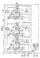
- the synthesis part ST which realizes equations (3) to (5) and is constructed with FIR filters is shown in FIG. 2.
- the bandpasses B1 ', B2', ... BM 'representing time-variant FIR filters are now used.
- the excitation variable x (n) is fed directly to the inputs of these bandpass filters in the form of a pulse train with a constant pulse amplitude.
- the time variance of the filters is controlled via the envelope values A1, A2 ... AM by weighting the filter coefficients hi (k) by forming the products gi (k). This weighting must be done once for each incoming frame of the sum signal ss for each filter.
- FIG. 3 shows a bandpass filter Bi 'in the form of such a time-variant FIR filter. It has N-1 identical delay stages Z- 1 and N taps connected in chain. The N taps are fed to control inputs of N switches S, which each connect the output of a multiplier MU to the sum line 1 supplying the filter response yi (n). Each multiplier MU assigned to a switch S is supplied with the associated envelope value Ai at its one input.
- the filter coefficients hi (0), hi (1), ... hi (N-1) are present at the N second inputs of the N multipliers MU.
- the excitation variable x (n) supplied to the input of the chain of delay elements has only the function of controlling the switches S "on or” within the filter, depending on whether no pulse or a pulse occurs. This has become possible because the excitation variable itself is no longer weighted by the envelope values.
- the transition from time-invariant to time-variant FIR filters thus saves M multipliers. As has already been mentioned, these multipliers can be designed in an extremely simple manner as sliding mechanisms, since the transmitted envelope values can only have values which are either zero or potencies of two for reasons of redundancy reduction.
- FIG. 4 shows an embodiment of the synthesis part ST according to FIG. 2, in which the bandpasses B1 ', B2' ... BM 'are combined to form a sum filter SB.
- a multiplier-summing arrangement MS is provided here, each of which has M multipliers. The outputs of the M multipliers are connected to the associated switch S via a summer SU.
- the filter coefficients hi (k) of all equivalent taps of the individual filters are supplied to one input of the M multipliers MU of a multiplier-summing arrangement MS, while the envelope values A1, A2 ... AM are present at their second inputs.
- the respective sum function connected to the sum line 1 and in this way the output signal y (n) obtained at the output of the synthesis part ST '.
- the transmission of the voiced-unvoiced criterion Sc and the random generator PNG can be dispensed with in an extremely advantageous manner in such a synthesis part with time-variant FIR filters with a suitable measurement of the filter coefficients defining the impulse response or the noise response will.
- This is shown schematically in Fig. 5.
- the filter coefficients hi '(k) are expediently determined here experimentally so that the synthesized speech signal has an optimal speech quality at the output. As has already been explained, this can be done in such a way that the filter coefficients hi '(n) of the band-pass filters B1', B2 '...
Abstract
Description
Die Erfindung bezieht sich auf eine Anordnung zur Übertragung von Sprache nach dem Kanalvocoderprinzip, bei dem sendeseitig in einem Vocoderanalysator vom zu übertragenden Sprachsignal Hüllkurvenwerte für eine durch eine Filterbank vorgegebene Anzahl von sich durch Frequenzlage undbreite unterscheidenden M Spektralkanälen sowie gegebenenfalls zusätzliche sprachspezifische Parameter, wie Sprachgrundfrequenz und Stimmcharakteristikum abgeleitet und in geeigneter Weise zu einem digitalen Summensignal zusammengefaßt im Rhythmus aufeinander folgender je ein Analyseintervall umfassenden Rahmen zur Empfangsseite übertragen werden, bei dem ferner das digitale Summensignal empfangsseitig wiederum auf die einzelnen M Spektralkanäle und gegebenenfalls auf die den zusätzlichen sprachspezifischen Paramatern zugeordneten Kanäle aufgeteilt wird und diese Kanalsignale anschließend dem empfangsseitigen Vocodersynthetisator zugeführt werden, der seinerseits eine dem sendeseitigen Vocoderanalysator entsprechende Filterbank sowie einen Pulsgenerator aufweist und ausgangsseitig das generierte synthetische Sprachsignal abgibt.The invention relates to an arrangement for the transmission of speech according to the channel vocoder principle, in which, in a vocoder analyzer on the transmission side, envelope values of the speech signal to be transmitted for a number of M spectral channels predetermined by a filter bank, as well as additional speech-specific parameters, such as basic speech frequency and width, differ by frequency position and width Vocal characteristics derived and combined in a suitable manner to form a digital sum signal in the rhythm of successive frames each comprising an analysis interval are transmitted to the reception side, in which furthermore the digital sum signal on the reception side is again divided into the individual M spectral channels and, if appropriate, the channels assigned to the additional language-specific parameters and these channel signals are then fed to the receiver-side vocoder synthesizer, which in turn corresponds to the transmitter-side vocoder analyzer has a computing filter bank and a pulse generator and outputs the generated synthetic speech signal on the output side.
Kanalvocoder-Übertragungsverfahren sind beispielsweise durch die Literatur IEEE Transactions on Audio and Electroacoustics, Vol. AU-15, Nr. 4, Dez. 1967, Seiten 148 bis 161 bekannt. In der Regel wird bei solchen Kanalvocodern im Analyseteil und im Syntheseteil von der gleichen Filterbank Gebrauch gemacht. Bei Sprachübertragung im Halbduplex ergibt sich hierdurch ein günstiger Aufwand, weil die Filterbank jeweils umgeschaltet werden kann und so nur einmal je Gerät vorhanden zu sein braucht.Channel vocoder transmission methods are known, for example, from the literature IEEE Transactions on Audio and Electroacoustics, Vol. AU-15, No. 4, Dec. 1967, pages 148 to 161. As a rule, the same filter bank is used for such channel vocoders in the analysis section and in the synthesis section. In the case of voice transmission in half duplex, this results in an inexpensive outlay because the filter bank can be switched over and thus only needs to be present once per device.
Der im Zuge der fortschreitenden integrierten Technik sich mehr und mehr vollziehende Übergang von analogen Schaltungen auf digitale Schaltungen führt auch dazu, Kanalvocoder ausschließlich in digitaler Technik zu realisieren. Wie beispielsweise die Literaturstelle IEEE Transactions on Acoustics, Speech, and Signal Processing, Vol. ASSP-29, Nr. 1 Febr. 1981, Seiten 13 bis 23, insbesondere Seite 16, rechte Spalte, erster Absatz ausweist, werden für die Realisierung der Filterbank in digitaler Ausführung IIR-Filter und FIR-Filter erwähnt. Der Aufwand für derartige Filter ist jedoch erheblich. Dies gilt insbesondere für das nicht rekursive Filter mit endlicher Impulsantwort (FIR-Fliter), weil dieses hierfür von hoher Ordnungszahl sein muß. Die digitalen rekursiven Filter mit unendlicher Impulsantwort (IIR-Filter) lassen sich zwar für den genannten Zweck mit wesentlich niedrigerer Ordnungszahl verwirklichen, haben jedoch nicht die günstigen Eigenschaften der FIR-Filter.The transition from analog circuits to digital circuits, which is taking place more and more in the course of advancing integrated technology, also leads to channel vocoders being implemented exclusively in digital technology. As the literature reference IEEE Transactions on Acoustics, Speech, and Signal Processing, Vol. ASSP-29, No. 1 Feb. 1981, pages 13 to 23, in particular page 16, right column, first paragraph shows, are used for the implementation of the filter bank mentioned in digital version IIR filter and FIR filter. However, the effort for such filters is considerable. This applies in particular to the non-recursive filter with a finite impulse response (FIR fliter), because this must be of a high atomic number. The digital recursive filter with an infinite impulse response (IIR filter) can be implemented with a significantly lower atomic number for the purpose mentioned, but does not have the favorable properties of the FIR filter.
Als digitale Filter können auch sogenannte « Switched capacitor-Filter » Verwendung finden, die in integrierter Ausführungsform zur Verfügung stehen und mit einem kleinen Einbauvolumen auskommen. Solche Filter haben jedoch wie alle Abtastfilter den Nachteil, daß sich ihre Übertragungsfunktion im Frequenzbereich periodisch wiederholt. Mit anderen Worten darf hier das Eingangssignal für ein solches Filter keine spektralen Anteile oberhalb der halben Abtastfrequenz besitzen. Wie die Praxis zeigt, muß hier die obere Bandgrenze des Eingangssignals noch einen größeren Abstand von der halben Abtastfrequenz aufweisen, wenn Störungen vermieden werden sollen. Hinsichtlich des Analyseteils ergeben sich hierdurch keine Probleme, da dieser Abstand mit einfachen Mitteln sicher eingehalten werden kann. Im Syntheseteil dagegen ist diese Forderung nicht ohne erheblichen Zusatzaufwand infolge der impulsförmigen Anregungsfunktion zu gewährleisten. Hier müssen mit anderen Worten erhebliche analoge Siebmittel aufgewendet werden, um störende Effekte in Form eines zwitschernden Hintergrundgeräusches in ausreichendem Maß zu unterdrücken.So-called “switched capacitor filters” can also be used as digital filters, which are available in an integrated embodiment and manage with a small installation volume. However, like all sampling filters, such filters have the disadvantage that their transfer function is repeated periodically in the frequency domain. In other words, the input signal for such a filter must not have any spectral components above half the sampling frequency. As practice shows, the upper band limit of the input signal must be further away from half the sampling frequency if interference is to be avoided. With regard to the analysis part, there are no problems with this, since this distance can be reliably maintained with simple means. In the synthesis part, on the other hand, this requirement cannot be guaranteed without considerable additional expenditure due to the pulse-shaped excitation function. In other words, considerable analog screening means have to be used here in order to sufficiently suppress disruptive effects in the form of a chirping background noise.
Der Erfindung liegt die Aufgabe zugrunde, für das Syntheseteil eines in digitaler Technik ausgeführten Kanalvocoders eine Lösung für eine digitale Filterbank aufzuzeigen, die bei relativ geringem technischen Aufwand eine optimale Sprachqualität der generierten synthetischen Sprache gewährleisten kann.The invention has for its object to provide a solution for a digital filter bank for the synthesis part of a channel vocoder implemented in digital technology, which can ensure optimal speech quality of the generated synthetic speech with relatively little technical effort.
Ausgehend von einer Anordnung zur Übertragung von Sprache nach dem Kanalvocoderprinzip der einleitend geschilderten Art wird diese Aufgabe gemäß der Erfindung dadurch gelöst, daß die in digitaler Technik gestaltete Filterbank aus nicht rekursiven zeitvarianten Filtern mit endlicher Impulsantwort (FIR-Filter) bestehen, daß ferner der Filterbank eingangsseitig die Anregungsgröße des Pulsgenerators mit konstanter Pulsamplitude zugeführt ist und daß die Zeitvarianz des Verstärkungsfaktors der Filterbank durch Multiplikation der Filterbankkoeffizienten mit den im Rhythmus aufeinander folgender Rahmen übertragenen Hüllkurvenwerten in Multiplizierern herbeigeführt ist.Starting from an arrangement for the transmission of speech according to the channel vocoder principle of the type described in the introduction, this object is achieved according to the invention in that the filter bank designed in digital technology consists of non-recursive time-variant filters with a finite impulse response (FIR filter) and that the filter bank the excitation variable of the pulse generator is supplied on the input side with a constant pulse amplitude and that the time variance of the gain factor of the filter bank is brought about in multipliers by multiplying the filter bank coefficients by the envelope values transmitted in rhythm with successive frames.
Bei der Erfindung wird von der wesentlichen Erkenntnis ausgegangen, daß es für die Impulsantwort eines FIR-Filters auf das gleiche hinausläuft, ob die seinem Eingang zugeführte Impulsfolge mit den übertragenen Hüllkurvenwerten gewichtet ist oder aber die Gewichtung über eine Multiplikation der Filterkoeffizienten mit den übertragenen Hüllkurvenwerten erfolgt. Die erfindungsgemäße Ausbildung der Filterbank als zeitvariante Filterbank, der eingangsseitig die Anregungsgröße des Pulsgenerators mit konstanter Amplitude zugeführt wird, vermindert in außerordentlich vorteilhafter Weise die im Syntheseteil durchzuführenden Multiplikationen und damit den Filteraufwand.The invention is based on the essential finding that the impulse response of a FIR filter amounts to the same whether the pulse train supplied to its input is weighted with the transmitted envelope values or the weighting is carried out by multiplying the filter coefficients by the transmitted envelope values . The inventive design of the filter bank as a time-variant filter bank, to the input side of which the excitation variable of the pulse generator is supplied with a constant amplitude, reduces in an extremely advantageous manner the multiplications to be carried out in the synthesis part and thus the filter effort.
Bei einer ersten bevorzugten Ausführungsform weisen die FIR-Filter, denen eingangsseitig die Anregungsgröße zugeführt ist, jeweils eine Kettenschaltung von N-1 gleichen Verzögerungsstufen mit maximal N Abgriffen auf. Jedes FIR-Filter hat eine den Abgriffen entsprechende Anzahl von Schaltern, deren Steuereingänge mit den Abgriffen verbunden sind. Jeder Schalter verbindet dabei den Ausgang eines Multiplizierers mit dem Filterausgang. Die einen Eingänge der Multiplizierer bilden gemeinsam den Eingang für den zugeordneten übertragenen Hüllkurvenwert und an jedem der anderen Eingänge der Multiplizierer steht ein Filterkoeffizient an, die in ihrer Gesamtheit die Filterantwort festlegen.In a first preferred embodiment, the FIR filters, to which the excitation variable is fed on the input side, each have a chain connection of N-1 identical delay stages with a maximum of N taps. Each FIR filter has a number of switches corresponding to the taps, the control inputs of which are connected to the taps. Each switch connects the output of a multiplier to the filter output. The inputs of the multipliers together form the Input for the assigned transmitted envelope value and at each of the other inputs of the multipliers there is a filter coefficient, which in their entirety determine the filter response.
Bei einer zweiten bevorzugten Anordnung ist die Filterbank ein FIR-Summenfilter, das eine Kettenschaltung von N-1 gleichen Verzögerungsstufen mit maximal N Abgriffen aufweist und eine den Abgriffen entsprechende Zahl von Schaltern hat, deren Steuereingänge mit den Abgriffen verbunden sind. Hierbei verbindet jeder Schalter den Ausgang einer Multiplizierer-Summierschaltung mit dem Filterausgang, die die Produktbildung der Einzelfilterkoeffizienten mit den zugehörigen übertragenen Hüllkurvenwerten ausführt und die Produktsumme bildet.In a second preferred arrangement, the filter bank is an FIR sum filter, which has a chain connection of N-1 equal delay stages with a maximum of N taps and has a number of switches corresponding to the taps, the control inputs of which are connected to the taps. Each switch connects the output of a multiplier summing circuit to the filter output, which carries out the product formation of the individual filter coefficients with the associated transmitted envelope values and forms the product sum.
Die üblicherweise aus Gründen der Redundanzreduktion ausschließlich in Potenzen von zwei übertragenen Hüllkurvenwerte geben die Möglichkeit, ihre Multiplikation mit den Filterkoeffizienten jeweils in einem Schiebewerk auszuführen, was eine weitere erhebliche Aufwandsminderung mit sich bringt.The usually for reasons of redundancy reduction exclusively in powers of two transmitted envelope values give the possibility of multiplying them with the filter coefficients in a sliding mechanism, which leads to a further considerable reduction in expenditure.
In Weiterbildung der Erfindung kann die den FIR-Filtern bzw. dem FIR-Summenfilter zugeführte Anregungsgröße unter Verzicht auf eine Stimmlos-Stimmhaft-Umschaltung eine von einem Pulsgenerator periodisch erzeugte und vom übertragenen Sprachgrundfrequenzwert in ihrer Folgefrequenz steuerbare Pulsfolge sein. In diesem Zusammenhang sind die Filterkoeffizienten derart bemessen, daß hierdurch eine optimale Sprachqualität der synthetisierten Sprache gewährleistet ist.In a further development of the invention, the excitation quantity supplied to the FIR filter or the FIR sum filter can be a pulse sequence that is generated periodically by a pulse generator and can be controlled in its repetition rate by the transmitted basic speech frequency value. In this context, the filter coefficients are dimensioned such that an optimal speech quality of the synthesized speech is guaranteed.
Eine erste derartige bevorzugte Bemessung kann darin bestehen, daß die Filterkoeffizienten der FIR-Filter bzw. der Filterbereiche des FIR-Summenfilters mit Mittenfrequenzen < 2 kHz für Impulsantworten und diejenigen der FIR-Filter bzw. der Filterbereiche des Summenfilters mit Mittenfrequenzen > 2 kHz für Rauschantworten bemessen sind.A first such preferred dimensioning can consist in that the filter coefficients of the FIR filter or the filter areas of the FIR sum filter with center frequencies <2 kHz for impulse responses and those of the FIR filters or the filter areas of the sum filter with center frequencies> 2 kHz for noise responses are measured.
Eine weitere bevorzugte Bemessung kann darin bestehen, daß sämtliche Filterkoeffizienten der FIR-Filter bzw. des FIR-Summenfilters für Rauschantworten bemessen sind.A further preferred dimensioning can consist in dimensioning all filter coefficients of the FIR filter or the FIR sum filter for noise responses.
Anhand von in der Zeichnung dargestellten Ausführungsbeispielen soll die Erfindung im folgenden noch näher erläutert werden. In der Zeichnung bedeuten
Figur 1 das Blockschaltbild des Syntheseteils eines üblichen Kanalvocoders,Figur 2 das Fig. 1 entsprechende Blockschaltbild eines erfindungsgemäßen Syntheseteils,- Figur 3 das Blockschaltbild eines digitalen Bandfilters des Syntheseteils nach Fig. 2,
- Figur 4 ein weiteres Syntheseteil mit einem digitalen Summenfilter nach der Erfindung,
- Figur 5 eine weitere Ausführungsform eines Syntheseteils nach der Erfindung in schematischer Darstellung.
- FIG. 1 shows the block diagram of the synthesis part of a conventional channel vocoder,
- 2 shows the block diagram corresponding to FIG. 1 of a synthetic part according to the invention,
- FIG. 3 shows the block diagram of a digital band filter of the synthesis part according to FIG. 2,
- FIG. 4 shows a further synthesis part with a digital sum filter according to the invention,
- Figure 5 shows a further embodiment of a synthetic part according to the invention in a schematic representation.
Die innerhalb eines Analyseintervalls auf der Sendeseite zu einem Zeitmultiplexrahmen zusammengefaßten Hüllkurvenwerte Ai sowie der Grundfrequenzinformation No und dem Stimmhaft-Stimmlos-Kriterium Sc werden auf der Empfangsseite im Demultiplexer DEMUX, dem eingangsseitig das Summensignal ss zugeführt wird, zunächst wieder in die einzelnen Kanäle, nämlich die M Spektralkanäle für die M Hüllkurvenwerte A1, A2 ... AM sowie den Kanal für das Stimmhaft-Stimmlos-Kriterium Sc und den Kanal für die Grundfrequenzinformation No aufgeteilt.The envelope values Ai combined within an analysis interval on the transmission side to form a time-division multiplex frame, as well as the fundamental frequency information No and the voiced-unvoiced criterion Sc are first of all returned to the individual channels, namely the channels, on the receiving side in the demultiplexer DEMUX, to which the sum signal ss is fed on the input side M spectral channels for the M envelope values A1, A2 ... AM as well as the channel for the voiced-unvoiced criterion Sc and the channel for the fundamental frequency information No are divided.
Das eigentliche Syntheseteil ST weist die Filterbank mit den Bandpässen B1, B2 ... BM auf, denen die Hüllkurvenwerte jeweils über einen Modulator M1, M2 ... MM zugeführt werden. Dem jeweils zweiten Eingang der Modulatoren wird in Abhängigkeit des Stimmhaft-Stimmlos-Kriteriums S über den Umschalter U entweder die Anregungsgröße x(n) in Form der vom Pulsgenerator PB erzeugten periodischen Pulsfolge oder aber in Form der von einem Zufaiisimpuisgenerator PNG erzeugten Pseudozufallsimpulsfolge zugeführt. Die an den Modulatorausgängen abgegebenen, durch die Hüllkurvenwerte A1, A2 ... AM gewichteten Impulse des Pulsgenerators PG bzw. des Zufallsimpulsgenerators PNG werden über die Bandfilter B1, B2 ... BM hinweggeführt. Die Filterantworten Y1(n), Y2(n) ... YM(n) werden anschließend über den Summierer SU zum synthetisierten Sprachsignal y(n) am Ausgang des Syntheseteils ST zusammengefaßt.The actual synthesis part ST has the filter bank with the bandpasses B1, B2 ... BM, to which the envelope values are fed via a modulator M1, M2 ... MM. Depending on the voiced-unvoiced criterion S, either the excitation variable x (n) in the form of the periodic pulse sequence generated by the pulse generator PB or in the form of the pseudo-random pulse sequence generated by a random pulse generator PNG is fed to the second input of the modulators. The pulses of the pulse generator PG or of the random pulse generator PNG which are output at the modulator outputs and weighted by the envelope values A1, A2 ... AM are passed over the bandpass filters B1, B2 ... BM. The filter responses Y1 (n), Y2 (n) ... YM (n) are then combined via the summer SU to the synthesized speech signal y (n) at the output of the synthesis part ST.
Für die Ausführung der Bandfilter B1, B2 ... BM als FIR-Filter ergibt sich für das Ausgangssignal y(n) unter Berücksichtigung der in Fig. 1 ebenfalls angeschriebenen Filterkoeffizienten h1(k), h2(k) ... hM(k) für diese Bandfilter die Beziehung![]()
![]()
Dabei ist davon ausgegangen, daß jedes der ein FIR-Filter darstellenden Bandfilter B1, B2 ... BM N Abgriffe aufweist und aus N-1 gleichen Verzögerungsgliedern mit der Verzögerungszeit die gleich des mittleren Zeitabstands zweier aufeinander folgender Impulse gewählt ist. Der Ausdruck in Gleichung (1) hinter dem ersten Summenzeichen stellt die jeweilige Filterantwort yi(n) dar, so daß sich die Gleichung (1) auch schreiben läßt![]()
![]()
Wie die Gleichung (1) erkennen läßt, ergibt sich für das Ausgangssignal y(n) das gleiche Ergebnis, wenn anstelle einer Gewichtung der vom Pulsgenerator DG bzw. vom Zufallsimpulsgenerator PNG gelieferten Anregungsgröße x(n) mit den Hüllkurvenwerten Ai die Filterkoeffizienten hi(k) mit den Hüllkurvenwerten Ai multipliziert werden. Die Gleichung (1) für das Ausgangssignal des Syntheseteils y(n) kann deshalb wie folgt umgeschrieben werden.![]()
![]()
Setzt man für das Produkt Ai - 'hi (k) = gi (k), so ergibt sich -
Der Ausdruck hinter dem ersten Summenzeichen stellt wiederum die Ausgangsfunktion yi(n) eines Einzelfilters dar, so daß auch hier gilt![]()
![]()
Das die Gleichungen (3) bis (5) realisierende, mit FIR-Filtern aufgebaute Syntheseteil ST ist in Fig. 2 dargestellt. Anstelle der zeitinverianten Bandpässe B1, B2 ... BM nach Fig.1 treten nunmehr die zeitvariante FIR-Filter darstellenden Bandpässe B1', B2', ... BM'. Die Anregungsgröße x(n) wird hier in Form einer Impulsfolge mit konstanter Impulsamplitude den Eingängen dieser Bandfilter unmittelbar zugeführt. Die Zeitvarianz der Filter wird über die Hüllkurvenwerte A1, A2 ... AM dadurch gesteuert, daß sie die Filterkoeffizienten hi(k) durch Bilden der Produkte gi(k) gewichten. Diese Gewichtung muß für jeden ankommenden Rahmen des Summensignals ss für jedes Filter einmal erfolgen.The synthesis part ST which realizes equations (3) to (5) and is constructed with FIR filters is shown in FIG. 2. Instead of the time-inverted bandpasses B1, B2 ... BM according to FIG. 1, the bandpasses B1 ', B2', ... BM 'representing time-variant FIR filters are now used. The excitation variable x (n) is fed directly to the inputs of these bandpass filters in the form of a pulse train with a constant pulse amplitude. The time variance of the filters is controlled via the envelope values A1, A2 ... AM by weighting the filter coefficients hi (k) by forming the products gi (k). This weighting must be done once for each incoming frame of the sum signal ss for each filter.
In Figur 3 ist ein Bandpaß Bi' in Gestalt eines solchen zeitvarianten FIR-Filters dargestellt. Es weist N-1 gleiche in Kette geschaltete Verzögerungsstufen Z-1 und N Abgriffe auf. Die N Abgriffe sind Steuereingängen von N Schaltern S zugeführt, die jeweils den Ausgang eines Multiplizierers MU mit der die Filterantwort yi(n) liefernden Summenleitung 1 verbinden. Jedem einem Schalter S zugeordneten Multiplizierer MU wird an seinem einen Eingang der zugehörige Hüllkurvenwert Ai zugeführt. An den N zweiten Eingängen der N Multiplizierer MU liegen die Filterkoeffizienten hi(0), hi(1), ... hi(N-1) an. Die dem Eingang der Kette aus Verzögerungsgliedern zugeführte Anregungsgröße x(n) hat innerhalb des Filters lediglich die Funktion einer Steuerung der Schalter S « auf oder « zu je nachdem, ob kein Impuls oder ein Impuls auftritt. Dies ist möglich geworden, da die Anregungsgröße selbst nicht mehr durch die Hüllkurvenwerte gewichtet ist. Der Übergang von zeitinvarianten zu zeitvarianten FIR-Filtern ermöglicht somit eine Einsparung von M Multiplizierern. Wie bereits erwähnt worden ist, können diese Multiplizierer in außerordentlich einfacher Weise als Schiebewerke ausgeführt sein, da die übertragenen Hüllkurvenwerte aus Gründen der Redundanzminderung lediglich Werte aufweisen können, die entweder Null oder Pötenzen-von zwei sind.FIG. 3 shows a bandpass filter Bi 'in the form of such a time-variant FIR filter. It has N-1 identical delay stages Z- 1 and N taps connected in chain. The N taps are fed to control inputs of N switches S, which each connect the output of a multiplier MU to the
Figur 4 zeigt eine Ausführung des Syntheseteils ST nach Fig. 2, bei dem die Bandpässe B1', B2'... BM' zu einem Summenfilter SB zusammengefaßt sind. Das Summenfilter SB des in Fig. 4 mit ST bezeichneten Syntheseteils weist entsprechend Fig. 3 weiderum die Kettenschaltung von N gleichen Verzögerungsstufen Z-1 mit N Abgriffen auf, die jeweils dem Steuereingang eines von N Schaltern zugeführt sind. Im Unterschied zum Einzelfilter nach Fig. 3 sind hier anstelle eines Multiplizierers eine Multiplizierer-Summieranordnung MS vorgesehen, die jeweils M Multiplizierer aufweisen. Die Ausgänge der M Multiplizierer sind über einen Summierer SU mit dem zugehörigen Schalter S verbunden. Am einen Eingang der M Multiplizierer MU einer Multiplizierer-Summieranordnung MS sind die Filterkoeffizienten hi(k) aller gleichwertigen Abgriffe der Einzelfilter zugeführt, während an ihren zweiten Eingängen die Hüllkurvenwerte A1, A2 ... AM anstehen. In Abhängigkeit davon, daß in einem vorgegebenen Zeitabschnitt ein Impuls der Anregungsgröße x(n) am Steuereingang eines Schalters anliegt oder nicht wird die jeweilige Summenfunktion![]()
![]()
Wie weitere der Erfindung zugrundeliegende Untersuchungen gezeigt haben, kann in außerordentlich vorteilhafter Weise bei einem solchen Syntheseteil mit zeitvarianten FIR-Filtern bei geeigneter Messung der die Impulsantwort bzw. die Rauschantwort festlegenden Filterkoeffizienten auf die Übertragung des Stimmhaft-Stimmlos-Kriteriums Sc sowie den Zufallsgenerator PNG verzichtet werden. Schematisch ist dieser Sachverhalt in Fig.5 dargestellt. Die Filterkoeffizienten hi' (k) werden hier zweckmäßig auf experimentellem Wege so festgelegt, daß das synthetisierte Sprachsignal am Ausgang eine optimale Sprachqualität aufweist. Dies kann, wie bereits ausgeführt worden ist, in der Weise erfolgen, daß die Filterkoeffizienten hi'(n) der Bandpässe B1', B2' ... BM' bzw. der Filterbereiche des Summenfilters SB mit Mittenfrequenzen < 2 kHz für Impulsantworten und diejenigen der Bandpässe bzw. der Filterbereiche des Summenfilters mit Mittenfrequenzen > 2 kHz für Rauschantworten bemessen werden. Es ist jedoch in außerordentlich vorteilhafter Weise auch möglich, sämtliche Filterkoeffizienten hi'(n) der Bandpässe bzw. des Summenfilters in geeigneter Weise für Rauschantworten zu bemessen.As further studies on which the invention is based have shown, the transmission of the voiced-unvoiced criterion Sc and the random generator PNG can be dispensed with in an extremely advantageous manner in such a synthesis part with time-variant FIR filters with a suitable measurement of the filter coefficients defining the impulse response or the noise response will. This is shown schematically in Fig. 5. The filter coefficients hi '(k) are expediently determined here experimentally so that the synthesized speech signal has an optimal speech quality at the output. As has already been explained, this can be done in such a way that the filter coefficients hi '(n) of the band-pass filters B1', B2 '... BM' or the filter areas of the sum filter SB with center frequencies <2 kHz for impulse responses and those the bandpasses or the filter areas of the sum filter are dimensioned with center frequencies> 2 kHz for noise responses. However, it is also possible in an extremely advantageous manner to dimension all filter coefficients hi '(n) of the bandpass filter or the sum filter in a suitable manner for noise responses.
Claims (7)
Applications Claiming Priority (2)
| Application Number | Priority Date | Filing Date | Title |
|---|---|---|---|
| DE19813137679 DE3137679A1 (en) | 1981-09-22 | 1981-09-22 | ARRANGEMENT FOR TRANSMITTING LANGUAGE ACCORDING TO THE CHANNEL VOCODER PRINCIPLE |
| DE3137679 | 1981-09-22 |
Publications (3)
| Publication Number | Publication Date |
|---|---|
| EP0075311A2 EP0075311A2 (en) | 1983-03-30 |
| EP0075311A3 EP0075311A3 (en) | 1984-02-01 |
| EP0075311B1 true EP0075311B1 (en) | 1986-08-20 |
Family
ID=6142325
Family Applications (1)
| Application Number | Title | Priority Date | Filing Date |
|---|---|---|---|
| EP82108691A Expired EP0075311B1 (en) | 1981-09-22 | 1982-09-20 | Arrangement for speech transmission based on the channel vocoder principle |
Country Status (4)
| Country | Link |
|---|---|
| US (1) | US4574392A (en) |
| EP (1) | EP0075311B1 (en) |
| JP (1) | JPS594720B2 (en) |
| DE (2) | DE3137679A1 (en) |
Families Citing this family (6)
| Publication number | Priority date | Publication date | Assignee | Title |
|---|---|---|---|---|
| CA1233891A (en) * | 1985-05-27 | 1988-03-08 | Peter Gillingham | Switched capacitor finite impulse response filter |
| DE3521413C2 (en) * | 1985-06-14 | 1995-09-21 | Daimler Benz Aerospace Ag | Radiotelephony arrangement |
| GB2182795B (en) * | 1985-11-12 | 1988-10-05 | Nat Res Dev | Apparatus and methods for speech analysis |
| JPS6345933A (en) * | 1986-04-15 | 1988-02-26 | Nec Corp | Privacy communication equipment |
| DE3826858A1 (en) * | 1988-08-08 | 1990-02-15 | Thomson Brandt Gmbh | Two-band filter |
| RU2584462C2 (en) * | 2014-06-10 | 2016-05-20 | Федеральное государственное образовательное бюджетное учреждение высшего профессионального образования Московский технический университет связи и информатики (ФГОБУ ВПО МТУСИ) | Method of transmitting and receiving signals presented by parameters of stepped modulation decomposition, and device therefor |
Family Cites Families (4)
| Publication number | Priority date | Publication date | Assignee | Title |
|---|---|---|---|---|
| AT272413B (en) * | 1967-06-29 | 1969-07-10 | Ibm Oesterreich Internationale | Device for speech synthesis for several speech channels |
| JPS5853358B2 (en) * | 1980-03-31 | 1983-11-29 | 株式会社東芝 | speech analysis device |
| US4377793A (en) * | 1981-01-13 | 1983-03-22 | Communications Satellite Corporation | Digital adaptive finite impulse response filter with large number of coefficients |
| JPS5833313A (en) * | 1981-08-21 | 1983-02-26 | Nec Corp | Transversal constant gain variable equalizer |
-
1981
- 1981-09-22 DE DE19813137679 patent/DE3137679A1/en not_active Withdrawn
-
1982
- 1982-07-22 US US06/400,958 patent/US4574392A/en not_active Expired - Fee Related
- 1982-09-20 JP JP57162426A patent/JPS594720B2/en not_active Expired
- 1982-09-20 DE DE8282108691T patent/DE3272737D1/en not_active Expired
- 1982-09-20 EP EP82108691A patent/EP0075311B1/en not_active Expired
Also Published As
| Publication number | Publication date |
|---|---|
| EP0075311A2 (en) | 1983-03-30 |
| JPS5870298A (en) | 1983-04-26 |
| US4574392A (en) | 1986-03-04 |
| EP0075311A3 (en) | 1984-02-01 |
| DE3137679A1 (en) | 1983-04-07 |
| DE3272737D1 (en) | 1986-09-25 |
| JPS594720B2 (en) | 1984-01-31 |
Similar Documents
| Publication | Publication Date | Title |
|---|---|---|
| DE102006047197B3 (en) | Device for processing realistic sub-band signal of multiple realistic sub-band signals, has weigher for weighing sub-band signal with weighing factor that is specified for sub-band signal around subband-signal to hold weight | |
| DE2818204C2 (en) | Signal processing system for deriving an output signal with reduced interference | |
| EP0065210B1 (en) | Electrical signal conditioning method with a digital filter device | |
| DE60317722T2 (en) | Method for reducing aliasing interference caused by the adjustment of the spectral envelope in real value filter banks | |
| DE3510660C2 (en) | ||
| EP0290790B1 (en) | Filter bank | |
| EP0052847A2 (en) | Method and circuit for converting the sampling frequency of a series of samples avoiding conversion into a continuous signal | |
| EP1525576B1 (en) | Arrangement and method for the generation of a complex spectral representation of a time-discrete signal | |
| EP0485390B1 (en) | Process for transmitting a signal | |
| EP0075311B1 (en) | Arrangement for speech transmission based on the channel vocoder principle | |
| EP0957471B1 (en) | Measuring process for loudness quality assessment of audio signals | |
| DE3702215C2 (en) | ||
| DE69628130T2 (en) | Digital narrow band filter | |
| EP0608281B1 (en) | Process for reducing frequency crosstalk during acoustic or optical signal transmission and/or recording | |
| DE3431141A1 (en) | Transverse filter echo canceller for long acoustic echoes | |
| DE3922469C2 (en) | ||
| DE3037276C2 (en) | Sound synthesizer | |
| EP0402519B1 (en) | Method and arrangement for treating the dynamic range of an adaptive recursive network for processing time-discrete signals | |
| EP0196413B1 (en) | Low or high pass shelving filter | |
| EP0155008B1 (en) | Digital filter circuit for dividing signals into subbands | |
| DE2011772B2 (en) | FILTER WITH PERIODIC FREQUENCY CHARACTERISTICS | |
| DE3732047C2 (en) | ||
| EP0012393A1 (en) | Clock controlled monolithically integrable scanning circuit | |
| DE2211376A1 (en) | Digital filter | |
| DE3734882C1 (en) | Radio-frequency mixer |
Legal Events
| Date | Code | Title | Description |
|---|---|---|---|
| PUAI | Public reference made under article 153(3) epc to a published international application that has entered the european phase |
Free format text: ORIGINAL CODE: 0009012 |
|
| AK | Designated contracting states |
Designated state(s): CH DE FR GB IT LI NL |
|
| PUAL | Search report despatched |
Free format text: ORIGINAL CODE: 0009013 |
|
| AK | Designated contracting states |
Designated state(s): CH DE FR GB IT LI NL |
|
| 17P | Request for examination filed |
Effective date: 19840705 |
|
| GRAA | (expected) grant |
Free format text: ORIGINAL CODE: 0009210 |
|
| AK | Designated contracting states |
Kind code of ref document: B1 Designated state(s): CH DE FR GB IT LI NL |
|
| REF | Corresponds to: |
Ref document number: 3272737 Country of ref document: DE Date of ref document: 19860925 |
|
| ET | Fr: translation filed | ||
| ITF | It: translation for a ep patent filed |
Owner name: STUDIO JAUMANN |
|
| PLBE | No opposition filed within time limit |
Free format text: ORIGINAL CODE: 0009261 |
|
| STAA | Information on the status of an ep patent application or granted ep patent |
Free format text: STATUS: NO OPPOSITION FILED WITHIN TIME LIMIT |
|
| 26N | No opposition filed | ||
| PGFP | Annual fee paid to national office [announced via postgrant information from national office to epo] |
Ref country code: GB Payment date: 19900816 Year of fee payment: 9 |
|
| PGFP | Annual fee paid to national office [announced via postgrant information from national office to epo] |
Ref country code: FR Payment date: 19900925 Year of fee payment: 9 |
|
| ITTA | It: last paid annual fee | ||
| PGFP | Annual fee paid to national office [announced via postgrant information from national office to epo] |
Ref country code: NL Payment date: 19900930 Year of fee payment: 9 |
|
| PGFP | Annual fee paid to national office [announced via postgrant information from national office to epo] |
Ref country code: CH Payment date: 19901217 Year of fee payment: 9 |
|
| PG25 | Lapsed in a contracting state [announced via postgrant information from national office to epo] |
Ref country code: GB Effective date: 19910920 |
|
| PG25 | Lapsed in a contracting state [announced via postgrant information from national office to epo] |
Ref country code: LI Effective date: 19910930 Ref country code: CH Effective date: 19910930 |
|
| PG25 | Lapsed in a contracting state [announced via postgrant information from national office to epo] |
Ref country code: NL Effective date: 19920401 |
|
| NLV4 | Nl: lapsed or anulled due to non-payment of the annual fee | ||
| GBPC | Gb: european patent ceased through non-payment of renewal fee | ||
| PG25 | Lapsed in a contracting state [announced via postgrant information from national office to epo] |
Ref country code: FR Effective date: 19920529 |
|
| REG | Reference to a national code |
Ref country code: CH Ref legal event code: PL |
|
| REG | Reference to a national code |
Ref country code: FR Ref legal event code: ST |
|
| PGFP | Annual fee paid to national office [announced via postgrant information from national office to epo] |
Ref country code: DE Payment date: 19921124 Year of fee payment: 11 |
|
| PG25 | Lapsed in a contracting state [announced via postgrant information from national office to epo] |
Ref country code: DE Effective date: 19940601 |