EP0075155B1 - Method of cleaning blind hole threads in reactor pressure vessels with removed or mounted reactor covers by means of a cleaning machine, and machine for carrying out this method - Google Patents
Method of cleaning blind hole threads in reactor pressure vessels with removed or mounted reactor covers by means of a cleaning machine, and machine for carrying out this method Download PDFInfo
- Publication number
- EP0075155B1 EP0075155B1 EP19820108082 EP82108082A EP0075155B1 EP 0075155 B1 EP0075155 B1 EP 0075155B1 EP 19820108082 EP19820108082 EP 19820108082 EP 82108082 A EP82108082 A EP 82108082A EP 0075155 B1 EP0075155 B1 EP 0075155B1
- Authority
- EP
- European Patent Office
- Prior art keywords
- driving
- shaft
- air
- exhaust
- cleaning
- Prior art date
- Legal status (The legal status is an assumption and is not a legal conclusion. Google has not performed a legal analysis and makes no representation as to the accuracy of the status listed.)
- Expired
Links
- 238000004140 cleaning Methods 0.000 title claims description 30
- 238000000034 method Methods 0.000 title claims description 16
- 235000013358 Solanum torvum Nutrition 0.000 claims description 4
- 240000002072 Solanum torvum Species 0.000 claims description 4
- 238000007789 sealing Methods 0.000 claims description 4
- 238000000926 separation method Methods 0.000 claims description 3
- 239000000725 suspension Substances 0.000 claims description 3
- 238000007689 inspection Methods 0.000 claims 2
- 239000011248 coating agent Substances 0.000 claims 1
- 238000000576 coating method Methods 0.000 claims 1
- 238000000151 deposition Methods 0.000 claims 1
- 230000008021 deposition Effects 0.000 claims 1
- 241000701811 Reindeer papillomavirus Species 0.000 description 13
- 238000007664 blowing Methods 0.000 description 5
- 238000012423 maintenance Methods 0.000 description 4
- 238000000605 extraction Methods 0.000 description 3
- 239000002245 particle Substances 0.000 description 3
- 241000196324 Embryophyta Species 0.000 description 2
- 241000446313 Lamella Species 0.000 description 2
- 238000011109 contamination Methods 0.000 description 2
- 230000008878 coupling Effects 0.000 description 2
- 238000010168 coupling process Methods 0.000 description 2
- 238000005859 coupling reaction Methods 0.000 description 2
- 230000000977 initiatory effect Effects 0.000 description 2
- CWQXQMHSOZUFJS-UHFFFAOYSA-N molybdenum disulfide Chemical compound S=[Mo]=S CWQXQMHSOZUFJS-UHFFFAOYSA-N 0.000 description 2
- 241001295925 Gegenes Species 0.000 description 1
- 229910000831 Steel Inorganic materials 0.000 description 1
- 238000005260 corrosion Methods 0.000 description 1
- 230000007797 corrosion Effects 0.000 description 1
- 230000001419 dependent effect Effects 0.000 description 1
- 239000000314 lubricant Substances 0.000 description 1
- 238000005461 lubrication Methods 0.000 description 1
- 239000010959 steel Substances 0.000 description 1
- 230000007704 transition Effects 0.000 description 1
- XLYOFNOQVPJJNP-UHFFFAOYSA-N water Substances O XLYOFNOQVPJJNP-UHFFFAOYSA-N 0.000 description 1
Images


Classifications
-
- B—PERFORMING OPERATIONS; TRANSPORTING
- B23—MACHINE TOOLS; METAL-WORKING NOT OTHERWISE PROVIDED FOR
- B23G—THREAD CUTTING; WORKING OF SCREWS, BOLT HEADS, OR NUTS, IN CONJUNCTION THEREWITH
- B23G1/00—Thread cutting; Automatic machines specially designed therefor
- B23G1/02—Thread cutting; Automatic machines specially designed therefor on an external or internal cylindrical or conical surface, e.g. on recesses
Definitions
- the invention relates to a method for cleaning blind hole threads in reactor pressure vessels of a nuclear power plant with the reactor cover on by a cleaning machine, essentially during the working stage, to which it is connected as a mobile hanging structure, and which in its upper area is designed in a known manner as a maintenance unit remotely controllable control block A and a drive upper part B arranged in a cylindrical housing for driving the brush head, blown air being supplied and extracted via the brush head to support cleaning.
- the speed of the hollow shaft is increased to the extent that the brushes engage under pressure in the threads to be cleaned due to the centrifugal force, without the lifting of the lowering movement caused by the air cylinder taking place.
- the cleaning head is moved out of the thread practically without contact with it, i.e. it is ineffective for the cleaning process.
- Devices of this type are suitable for cleaning external threads.
- the device must be easy to use if the shortest changeover times are observed.
- the step-like machine constructed from five main parts A to E and constructed as a hanging structure, is connected in a manner known per se via mobile means of the working platform which can be adjusted both vertically and in terms of their boom width. These means allow an exact entry into the respective working position, this operation being completed by moving the lower drive part D into the corresponding passage opening of the RPV cover for this aid.
- the machine is controlled further by actuating the remote control keyboard connected to control head A.
- this houses the main valve for the pneumatic control, whereby compressed air connections are provided for supplying the machine with control air, with working air for driving the drive motor and for supplying the area to be cleaned with blown air.
- the directional valve switch Connected to the control block is the directional valve switch arranged in the upper area of the housing for initiating the commands "engine start, clockwise rotation” and “blowing air on”, and in the lower area a second directional valve switch to be set according to the desired travel distance for initiating the commands "engine” -Stop “and” Motor start counter-clockwise rotation ".
- the blowing air does not settle until the brush head emerges from the thread and is generally given when the brush head or the drive unit carrying it is reached again.
- the initially given forced guidance of the brush head in the axial direction by the lifting cylinder ensures its exact engagement in the thread and in the opposite direction, after completion of its cleaning process, its perfect removal from the thread, so that "regrinding" of the first threads is avoided.
- the blown air inlet via the brush head in conjunction with the effective extraction of the area to be cleaned, protects the operating personnel from any risk of contamination.
- the blowing air opens into two ring channels, starting from a central supply and arranged in radially directed connections at different levels, the channel leading first into the thread and lying at the bottom transferring the blowing air in the direction of the nozzles, which loosen the loosening causing the buildup while the overhead ring channel transfers the air to the radial circular brushes to assist in final cleaning, and
- the supply of the blown air via two different levels into the thread while at the same time supplying a partial air quantity directed against the root of the thread ensures an optimal loosening and cleaning with simultaneous adjustment of flows effective for the exhaust air extraction.
- a proposed combination of radially directed round brushes and plate brushes arranged parallel to the shaft and directed against the bottom of the thread is particularly cleaning-intensive.
- the brush head or the blown air supply in the cleaning area can be freely designed and adapted to the respective requirements.
- the brush head e.g. is interchangeable with a so-called molycotization device.
- This consists of a felt disc package soaked with Molykote, which is cylindrical and corresponds to the thread diameter, which enables intensive thread care after cleaning.
- the air to be extracted is captured by suction nozzles attached to the brush head and, via a pipe encasing the tool carrier shaft and rotatably connected to it, opens into a sealingly displaceable exhaust air collection chamber, while the tool carrier: shaft, furthermore also sealing, leads through this chamber, and that the exhaust air of the exhaust air collection chamber is guided via at least one suction pipe designed as a telescopic pull into the intermediate piece and from there is connected via further connections to the plant network equipped with suitable filters.
- the exhaust air supply in the intermediate piece takes place via at least one flexible detachable line.
- the flexible hose lines can be loosened and the actual suction pipes can be pierced from top to bottom with suitable aids, so that the loosened dirt particles, which essentially accumulate in the exhaust air collection chamber, when the connection in the intermediate piece is restored, through Suction can also be fed to the factory network.
- the clear structure of the drive unit for the tool carrier shaft arranged in the housing of the upper drive part and the means for connecting or disconnecting it from the lifting cylinder allow simple control and maintenance via an assembly cover arranged in the housing of the upper drive part.
- the guidance of the drive carrier plate in the housing arranged axially parallel to the tool carrier shaft ensures, in cooperation with the other guide means of the tool carrier shaft, their tilt-free axial guidance.
- control block A equipped with a main valve.
- compressed air connections A ' are provided for supplying the machine with control air, with working air for driving the drive motor, which is preferably designed as a compressed air vane motor 8, and for supplying the cleaning area with blown air.
- control block A is connected to suction line A "and the suspension for the machine. Furthermore, control block A is designed as a maintenance unit for lubrication, water separation, etc., and is provided with connections for pneumatic remote control A" of the machine.
- the control block A is adjoined at the bottom by the cylindrical housing 17 of the drive upper part B, the head 2 of the tool carrier shaft 1 being rotatably guided axially and radially in a long bearing combination 3 designed for the blown air supply 4.
- the tool carrier shaft head 2 passes through the drive carrier plate 5 and is then, i.e. arranged underneath, positively connected to a spur gear 6, the sprocket 7 engaging in this spur gear 6 also the pinion 7, which is also arranged below the drive carrier plate 5, axially parallel to the tool carrier shaft 1 and is driven by a compressed air lamella motor 8 installed on the drive carrier plate 5.
- the lifting cam 9 is provided axially parallel to the tool carrier shaft 1 for the engagement of a lifting lug 10 on the drive carrier plate 5, which is pivotally connected to the head of the piston rod 12 of the lifting cylinder 11 and initially engages in the lifting cam 9 in a form-fitting manner.
- the drive carrier plate 5 is guided in cylindrical columns 13 arranged axially parallel to the tool carrier shaft 1.
- the essential parts of the drive are arranged in the housing 17 via a large lockable
- Commissioning usually takes place after the lower drive part D (ie the guide tube) has been moved into the RPV cover, an intermediate piece C described later being flanged between the lower drive part D and the upper drive part B, which is supported via the flange 37 of the lower drive part D described later .
- the further commissioning is effected by the actuation of the lifting cylinder 11, which in turn causes a roller lever 15 to actuate the directional control valve switch "engine start-clockwise rotation” and "blown air on” in the course of its stroke.
- the lifting cylinder 11 guides the drive carrier plate 5 downwards until the brush head E engages in the thread in the RPV, in which position the stroke path of the piston rod 12 of the lifting cylinder 11, which is controlled by a linkage 16, swings the lifting lug 10 out of the lifting cam 9 and thus the further movement of the tool carrier shaft 1 releases.
- the tool carrier shaft 1 is now moved independently of the lifting cylinder 11 by positive locking between the brush head E carried by it with the thread to be cleaned, i.e. the brush head E is screwed into the thread.
- the screw-in path of the brush head E generally corresponds to the thread length, the lowest point being determined by a lower roller lever 15 'for actuating the directional control valve switches "motor stop” and "motor start anticlockwise rotation”.
- a rope pulleys 19 and 19 in the cylindrical housing 17 of the upper drive part B In order to relieve the brush elements due to the weight of the drive unit 8/5/6/7 etc., as well as the tool carrier shaft 1 and parts of the suction device, in particular when the brush head E is being raised, there is a rope pulleys 19 and 19 in the cylindrical housing 17 of the upper drive part B. 'Integrated counterweight 18 integrated, the position of the weight 18 is fixed within the housing 17 in its axial direction by guide columns 18'.
- a rope pulley 19 is connected to the upper end flange 20 of the housing 17 and a rope pulley 19 'to the lower end flange 20' of the housing 17 and to the counterweight 18 via a rope 19 "with the parts to be relieved.
- the counterweight 18 is a molded body that spares the drive parts, exhaust air ducts, etc.
- the blown air duct 4 opens into the annular space 3 'formed by the long bearing combination 3.
- the long bearing combination 3 is connected to the drive carrier plate 5.
- the head 2 of the tool carrier shaft 1 is axially and radially guided in this long bearing combination 3.
- the compressed air is guided via a control valve into the annular space 3 ′ given there and enters through radially directed bores 21 into a bore 22 directed centrally through the tool carrier shaft head 2, the head 2 into a bore connected to it Transferred precision steel tube 23, which essentially forms the tool carrier shaft 1.
- the tool carrier shaft 1 leads into an end piece 24 delimited by flange 25, the flange 25 also being the carrier of the casing tube 26 for the exhaust air supply described later.
- the tool carrier shaft 1 can be separated in the intermediate piece C by a coupling 27.
- the actual brush head E is connected to the flange 25 and generally has four radially directed round brushes 28 and two plate brushes 29 axially directed against the thread root in the RPV.
- the air is guided centrally in this area.
- the blown air enters from here radially in two superimposed planes annular channels 30 and 30 ', which are open in the area of the radially directed round brushes 28, and enters the threads via additional directional nozzles 30 ".
- the axial continuation of this central blown air supply tapers against the nozzle-shaped end, this end 31 leading the blown air against the bottom of the blind hole thread of the RPV.
- this brush head E another head can be put on, this one consists of felt disks 40 corresponding to the thread, which are generally impregnated with molykote.
- the suction serves to remove the dirt particles cleaned from the threads and it connects to the control block A and leads further through the cylindrical housing 17 of the upper drive part B, through the intermediate piece C, through the lower drive part D designed as a guide tube and from there into the Tool jacket shaft 1 comprising a suction jacket pipe 26, in order to ultimately open into two suction ports 32 connected to the brush head E and the tool table shaft 1.
- the rotating suction jacket tube 26 opens in the direction of suction in the lower drive part D into a non-rotating exhaust air collection chamber 33 which is adjustable in its axial direction, and which seals against it.
- the actual tool carrier shaft 1 leads in the further passage through this chamber 33 and emerges from it together with the chamber 33 in an axially displaceable manner and is sealed against it.
- Fixed exhaust pipes 34 are connected to the exhaust air collection chamber 33, each of which is designed as a telescopic cable 35 leading upwards.
- the tubes end in the lower limiting flange 36 of the intermediate piece C leading to the upper drive part B.
- the intermediate piece C is based on a flange 37 which is claw-shaped on one side, which acts as a torque support against the RPV cover.
- two suction pipes 34 lead from the exhaust air collection chamber 33 through the lower drive part D into the intermediate piece C.
- the respective opening area of the respective suction pipe 34 is connected via a detachable hose connection 38 to the suction pipe 34 'leading through the upper drive part B, respectively.
- the intermediate piece C the upper part of the tool carrier shaft 1 can also be separated from the lower part thereof by the coupling 27.
- the intermediate piece C is provided with a mounting cover 39, so that from here the tool carrier shaft 1 can be separated and replacement parts can be installed.
- the hose connections 38 of the suction pipes 34/34 ' can be removed, so that from here each suction pipe 34, e.g. by ejecting it with suitable aids.
- the suction pipes 34 ' are connected to the plant network by B and A and the extracted air is cleaned in suitable filters.
- This machine can also be used to clean dismantled nuts on a separate parking ring.
- the flexible suction line on control block A is removed.
- the suction then takes place via an adapter 41 which engages over the nut and to which a modified suction line 42, which also leads to a filter device, is connected at the bottom.
- the workplace is ventilated here via the exposed suction lines.
- a second idler pinion 7 'engaging in the spur gear 6 is provided, which can be driven by means of a crank handle 7 "working platform which engages through the drive carrier plate 5. The brush head E can thus be screwed back manually.
Landscapes
- Engineering & Computer Science (AREA)
- Mechanical Engineering (AREA)
- Cleaning In General (AREA)
Description
Die Erfindung betrifft ein Verfahren zur Reinigung von Sacklochgewinden in Reaktor-Druckbehältern eines Kernkraftwerkes bei aufliegendem Reaktordeckel durch eine Reinigungsmaschine, im wesentlichen während der beitsbühne aus, der sie als mobile Hängekonstruktion verbunden ist, und die in ihrem oberen Bereich in bekannter Weise einen als Wartungseinheit ausgebildeten fernbedienbaren Steuerblock A und ein in einem zylindrischen Gehäuse angeordnetes Antriebsoberteil B zum Antrieb des Bürstenkopfes aufweist, wobei zur Unterstützung der Reinigung über den Bürstenkopf Blasluft zugeführt und abgesaugt wird.The invention relates to a method for cleaning blind hole threads in reactor pressure vessels of a nuclear power plant with the reactor cover on by a cleaning machine, essentially during the working stage, to which it is connected as a mobile hanging structure, and which in its upper area is designed in a known manner as a maintenance unit remotely controllable control block A and a drive upper part B arranged in a cylindrical housing for driving the brush head, blown air being supplied and extracted via the brush head to support cleaning.
Durch die DE-OS 26 06 214 ist ein Gerät zum Reinigen der Gewindegänge von in dem oberen Rand des Druckgefäßes eines Kernkraftwerkes eingearbeiteten Gewindelöchern bekannt, deren Kriterium mindestens eine fernbedienbare und umlaufende, in das betreffende Gewindeloch absenkbare Reinigungsbürste ist, die auf einer dem zu reinigenden Gewinde parallelen Kreisbahn geführt ist, wobei die Vorrichtung als solche durch die Ansprüche 18 bis 22 beschrieben ist, und nach den gegebenen Ausführungen auf Seite 18 ein solches Gerät von der Arbeitsbühne aus an einem Tragseil soweit abgesenkt wird, bis der abschließende, in der Regel über zwei Gewindelöcher greifende Flansch mit Führungskegel in die benachbarten Gewindelöcher eingreift.From DE-OS 26 06 214 a device for cleaning the threads of threaded holes machined in the upper edge of the pressure vessel of a nuclear power plant is known, the criterion of which is at least one remote-controlled and rotating cleaning brush that can be lowered into the threaded hole in question and which is to be cleaned on the one Thread parallel circular path is guided, the device as such is described by
Erst nach Einnahme dieser Arbeitsstellung wird durch einen Luftmotor die den Bürstensatz tragende Hohlwelle in Umdrehung versetzt und bei geringer Drehzahl durch einen elektromagnetisch gesteuerten Luftzylinder ein langsames Absenken der lediglich axial verschiebbaren, die drehende Hohlwelle axial unverschiebbar tragenden Führungshülse bewirkt, wobei die Hohlwelle wiederum Träger des Bürstensatzes ist.Only after this working position has been taken is the hollow shaft carrying the brush set rotated by an air motor and, at low speed, an electromagnetically controlled air cylinder slowly lowers the only axially displaceable guide sleeve which carries the rotating hollow shaft axially immovably, the hollow shaft in turn carrying the brush set is.
Nach Eingriff des Bürstensatzes in den Bereich der oberen Gewinde wird die Drehzahl der Hohlwelle insoweit erhöht, daß die Bürsten aufgrund der Fliehkraft unter Druck in die zu reinigenden Gewindegänge eingreifen, ohne daß dabei eine Aufhebung der durch den Luftzylinder veranlaßten absenkenden Bewegung stattfindet.After engagement of the brush set in the area of the upper thread, the speed of the hollow shaft is increased to the extent that the brushes engage under pressure in the threads to be cleaned due to the centrifugal force, without the lifting of the lowering movement caused by the air cylinder taking place.
Bei Erreichung einer durch Anschlag vorbestimmten Tiefstellung wird der Luftmotor stillgesetzt und die Rückführung der Reinigungsbürste der Hohlwelle und der Hülse durch den elektromagnetisch gesteuerten Luftzylinder in eine obere Anschlagstellung bewirkt, wobei bei der Ausführung des Reinigungskopfes aus dem Gewinde durch den dann gegebenen Fortfall der Fliehkraft der Eingriff der Bürsten in das Gewinde aufgehoben ist und diese, bedingt durch Federwirkung, in ihre Ruhestellung zurückgeführt sind.When a predetermined low position reached by a stop is reached, the air motor is stopped and the return of the cleaning brush of the hollow shaft and the sleeve to the upper stop position is effected by the electromagnetically controlled air cylinder, the engagement then taking place when the cleaning head is made out of the thread due to the loss of centrifugal force the brushes are lifted into the thread and, due to spring action, these are returned to their rest position.
Das Herausfahren des Reinigungskopfes aus dem Gewinde erfolgt also praktisch ohne Kontakt mit diesem, d.h. es ist für den Reinigungsvorgang wirkungslos.The cleaning head is moved out of the thread practically without contact with it, i.e. it is ineffective for the cleaning process.
Zusammenfassend ist zu der DE-OS 26 06 214 zu bemerken, daß die Lockerung und die Abreinigung der Gewindegänge von Verschmutzungen lediglich durch mechanischen Angriff erfolgt, wobei die Entfernung der mechanisch gelösten Verschmutzung durch deren Absaugung stattfindet.To sum up with DE-OS 26 06 214 it should be noted that the loosening and the cleaning of the threads of dirt is only carried out by mechanical attack, the removal of the mechanically loosened dirt taking place by its suction.
Die Niederbringung des Bürstenkopfes durch einen Hubzylinder, bei gleichzeitigem Eingriff der Bürsten in die Gewindegänge, führt zwangsläufig zu einer erhöhten abrasiven Beanspruchung der Gewindeflanken, da der Reinigungskopf nicht entsprechend der Gewindesteigung "eingeschraubt", sondern entsprechend dem Vorschub des Zylinders geschoben wird.The lowering of the brush head by a lifting cylinder, with simultaneous engagement of the brushes in the threads, inevitably leads to an increased abrasive stress on the thread flanks, since the cleaning head is not "screwed in" according to the thread pitch, but is pushed according to the feed of the cylinder.
Durch die meist gegebene große Entfernung zwischen Arbeitsbühne und RDB werden die schon erwähnten Führungsprobleme noch erschwert.The above-mentioned large distance between the working platform and the RPV makes the aforementioned management problems even more difficult.
Einrichtungen dieser Art sind für die Reinigung von Außengewinden geeignet.Devices of this type are suitable for cleaning external threads.
Aufgrund dieser Sachlage, ist es Aufgabe dieser Erfindung, ein Verfahren nach der eingangs beschriebenen Art sowie eine Vorrichtung zur Durchführung des Verfahrens zu nennen, das speziell darauf abgestimmt ist, die Sacklochgewinde eines RDB, bei Aufrechterhaltung der Auflage des RDB-Deckels, mit großer Wirksamkeit und Aufrechterhaltung einer bis zum Gewindegrund reichenden gleichmäßigen Reinigungsintensität, bei gleichzeitigem Ausschluß jeder Kontaminationsgefahr für das Bedienungspersonal und schadloser Beseitigung der von den Gewinden gelösten Korrosions- und Schmiermittelrückständen zu ermöglichen.Because of this situation, it is the object of this invention to name a method of the type described above and an apparatus for carrying out the method, which is specifically adapted to the blind hole thread of an RPV, while maintaining the support of the RPV cover, with great effectiveness and maintenance of a uniform cleaning intensity reaching to the bottom of the thread, while at the same time excluding any risk of contamination for the operating personnel and without damage removal of the loosened corrosion and lubricant residues from the threads.
Die Vorrichtung muß bei Einhaltung kürzester Umrüstzeiten einfach zu handhaben sein.The device must be easy to use if the shortest changeover times are observed.
Die erfindungsgemäße Lösung dieser Aufgabe sieht vor,
- daß die im weiteren stufenförmig von oben nach unten aufgebaute Maschine, bestehend aus:
- einem zylindrischen Zwischenstück C für die Trennung der bzw. des Absaugerohre(s) und der Werkzeugträgerwelle;
- einem Antriebsunterteil D, das gleichzeitig Führungsrohr für den Durchgang durch den RDB-Deckel ist und dessen Länge mit der Flanschstärke dieses Deckels korrespondiert, wobei dessen oberer zum Zwischenstück C gerichteter begrenzender Flansch, einseitig klauenförmig über den RDB-Deckel greifend als Drehmomentenstütze ausgebildet ist, und im Bereich des Überganges zum eigentlichen Führungsrohr eine gegen den RDB-Deckel abdichtende Dichtung vorgesehen ist, sowie weiter im Antriebsunterteil D, korrespondierend mit dem Aus- bzw. Einfahrweg der Werkzeugträgerwelle, eine sich bewegende Absaugeeinrichtung abdichtend geführt ist, und
- daß im weiteren die sich drehende Werkzeugträgerwelle durch Formschluß zwischen dem von ihr getragenen Bürstenkopf mit dem zu reinigenden Gewinde so lange nach unten bewegt wird, bis ein zweiter, wegeabhängiger Schalter "Motor-Stop" und "Motor-Start-Linkslauf" bestimmt und sich der Bürstenkopf E nunmehr bis zu seiner Wiedereinkupplung mit dem Hubzylinder nach oben schraubt.
- that the machine, which is built up step by step from top to bottom, consists of:
- a cylindrical intermediate piece C for the separation of the suction tube (s) and the tool carrier shaft;
- a lower drive part D, which is at the same time a guide tube for the passage through the RPV cover and the length of which corresponds to the flange thickness of this cover, its upper delimiting flange directed towards the intermediate piece C, being claw-shaped on one side as a torque support, and in the area of the transition to the actual guide tube, a seal sealing against the RPV cover is provided, and further in the lower drive part D, corresponding to the extension and retraction path of the tool carrier shaft, a moving suction device is sealingly guided, and
- that further the rotating tool carrier shaft by positive locking between the brush head carried by it with the cleaning thread is moved down until a second, path-dependent switch "motor stop" and "motor start anticlockwise rotation" is determined and the brush head E is now screwed up until it is reconnected with the lifting cylinder.
Die stufenförmig, aus fünf Hauptteilen A bis E, aufgebaute, als Hängekonstruktion ausgebildete Maschine, ist in an sich bekannter Weise über mobile, sowohl in der Vertikalen als auch in ihrer Auslegerweite einstellbare Mittel der Arbeitsbühne verbunden. Diese Mittel lassen ein genaues Einfahren in die jeweilige Arbeitsposition zu, wobei dieser Vorgang durch Verbringung des Antriebsunterteiles D in die entsprechende DurchgangsÖffnung des RDB-Deckels für dieses Hilfsmittel jeweils beendet ist.The step-like machine, constructed from five main parts A to E and constructed as a hanging structure, is connected in a manner known per se via mobile means of the working platform which can be adjusted both vertically and in terms of their boom width. These means allow an exact entry into the respective working position, this operation being completed by moving the lower drive part D into the corresponding passage opening of the RPV cover for this aid.
Die weitere Steuerung der Maschine erfolgt durch Betätigung der mit dem Steuerkopf A verbundenen Fernbedienungstastatur.The machine is controlled further by actuating the remote control keyboard connected to control head A.
Zum Steuerblock ist zu bemerken, daB dieser das Hauptventil für die pneumatische Steuerung aufnimmt, wobei im einzelnen Druckluftanschlüsse für die Versorgung der Maschine mit Steuerluft, mit Arbeitsluft für den Antrieb des Antriebsmotors und zur Versorgung des abzureinigenden Bereiches mit Blasluft vorgesehen sind.Regarding the control block, it should be noted that this houses the main valve for the pneumatic control, whereby compressed air connections are provided for supplying the machine with control air, with working air for driving the drive motor and for supplying the area to be cleaned with blown air.
Dem Steuerblock verbunden ist der im oberen Bereich des Gehäuses angeordnete Wegeventilschalter für die Veranlassung der Befehle "Motor-Start-Rechtslauf" und "Blasluft-Ein", sowie im unteren Bereich ein zweiter, entsprechend dem gewünschten Hubweg einzustellender Wegeventilschalter zur Veranlassung der Befehle "Motor-Stop" und "Motor-Start-Linkslauf". Das Absetzender Blasluft erfolgt erst mit dem Austritt des Bürstenkopfes aus dem Gewinde und wird in der Regel bei Wiedererreichung der Ausgangslage des Bürstenkopfes bzw. der ihn tragenden Antriebseinheit gegeben. Die zunächst gegebene Zwangsführung des Bürstenkopfes in der axialen Richtung durch den Hubzylinder sichert dessen exakten Eingriff in das Gewinde und in umgekehrter Richtung, nach Beendigung dessen Reinigungsvorganges, dessen einwandfreie Lösung vom Gewinde, so daß ein "Nachschleifen" der ersten Gewindegänge vermieden wird.Connected to the control block is the directional valve switch arranged in the upper area of the housing for initiating the commands "engine start, clockwise rotation" and "blowing air on", and in the lower area a second directional valve switch to be set according to the desired travel distance for initiating the commands "engine" -Stop "and" Motor start counter-clockwise rotation ". The blowing air does not settle until the brush head emerges from the thread and is generally given when the brush head or the drive unit carrying it is reached again. The initially given forced guidance of the brush head in the axial direction by the lifting cylinder ensures its exact engagement in the thread and in the opposite direction, after completion of its cleaning process, its perfect removal from the thread, so that "regrinding" of the first threads is avoided.
Die Blaslufteinführung über den Bürstenkopf schützt, in Verbindung mit der gleichzeitig wirksamen Absaugung des abzureinigenden Raumes, das Bedienungspersonal vor jeder Kontaminationsgefahr.The blown air inlet via the brush head, in conjunction with the effective extraction of the area to be cleaned, protects the operating personnel from any risk of contamination.
Zur Blaslufteinführung wird vorgeschlagen, daß die Blasluft in zwei von einer zentrischen Zuführung ausgehende, über in radial gerichtete Verbindungen in verschiedenen Ebenen angeordnete Ringkanäle einmündet, wobei der zuerst in das Gewinde einführende, unten liegende Kanal die Blasluft in Richtung der Düsen überführt, die die Auflockerung der Anhaftungen veranlassen, während der oben liegende Ringkanal die Luft zu den radial gerichteten Rundbürsten zur Unterstützung der Endabreinigung überführt, undFor the blowing air introduction, it is proposed that the blowing air opens into two ring channels, starting from a central supply and arranged in radially directed connections at different levels, the channel leading first into the thread and lying at the bottom transferring the blowing air in the direction of the nozzles, which loosen the loosening causing the buildup while the overhead ring channel transfers the air to the radial circular brushes to assist in final cleaning, and
daß die Fortsetzung der zentralen Luftzuführung in einen gegen das Ende, düsenförmig sich verengenden Austritt einmündet, und die Luft gegen den Grund des Sacklochgewindes führt, wo sie, in Verbindung mit vertikal gerichteten Tellerbürsten, die Ablagerungen abhebt und der Absaugung zugänglich macht.that the continuation of the central air supply leads into an outlet which narrows towards the end in the shape of a nozzle, and the air leads to the bottom of the blind hole thread, where, in conjunction with vertically oriented disc brushes, it lifts off the deposits and makes them accessible for suction.
Die Zuführung der Blasluft über zwei verschiedene Ebenen in das Gewinde bei gleichzeitiger Zuführung einer gegen den Gewindegrund gerichteten Teilluftmenge sichert eine optimale Auflockerung und Abreinigung bei gleichzeitiger Einstellung von für die Abluftabsaugung wirksamen Strömungen. Eine vorgesehene Kombination von radial gerichteten Rundbürsten und von achsparallel zur Welle angeordneten, gegen den Grund des Gewindes gerichteten Tellerbürsten, ist besonders reinigungsintensiv.The supply of the blown air via two different levels into the thread while at the same time supplying a partial air quantity directed against the root of the thread ensures an optimal loosening and cleaning with simultaneous adjustment of flows effective for the exhaust air extraction. A proposed combination of radially directed round brushes and plate brushes arranged parallel to the shaft and directed against the bottom of the thread is particularly cleaning-intensive.
Selbstverständlich ist der Bürstenkopf bzw. die Blasluftzuführung im Reinigungsbereich frei gestaltbar und den jeweiligen Anforderungen anpaßbar.Of course, the brush head or the blown air supply in the cleaning area can be freely designed and adapted to the respective requirements.
In diesem Zusammenhang soll erwähnt werden, daß der Bürstenkopf z.B. gegen eine sogenannte Molykotisierungseinrichtung austauschbar ist.In this context it should be mentioned that the brush head e.g. is interchangeable with a so-called molycotization device.
Diese besteht aus einem mit Molykote getränkten, zylindrisch entsprechend dem Gewindedurchmesser ausgebildeten Filzscheibenpaket, das eine intensive Gewindepflege nach vollzogener Reinigung ermöglicht.This consists of a felt disc package soaked with Molykote, which is cylindrical and corresponds to the thread diameter, which enables intensive thread care after cleaning.
Zur Konzeption der Absaugung ist zu bemerken, daß die abzusaugende Luft durch am Bürstenkopf ansetzende Absaugehutzen erfaßt wird und über ein die Werkzeugträgerwelle ummantelndes, mit dieser drehend verbundenes Rohr in eine lediglich in der Vertikalen verschiebbaren Abluftsammelkammer abdichtend einmündet, während die Werkzeugträger: welle, im weiteren ebenfalls abdichtend, durch diese Kammer hindurch führt, und daß die Abluft der Abluftsammelkammer über mindestens ein als Teleskopzug ausgebildetes in das Zwischenstück einmündendes Absaugerohr geführt wird und von hier über weitere Verbindungen dem mit geeigneten Filtern ausgerüsteten Werknetz angeschlossen wird.With regard to the design of the extraction system, it should be noted that the air to be extracted is captured by suction nozzles attached to the brush head and, via a pipe encasing the tool carrier shaft and rotatably connected to it, opens into a sealingly displaceable exhaust air collection chamber, while the tool carrier: shaft, furthermore also sealing, leads through this chamber, and that the exhaust air of the exhaust air collection chamber is guided via at least one suction pipe designed as a telescopic pull into the intermediate piece and from there is connected via further connections to the plant network equipped with suitable filters.
Die unmittelbare Absaugung der mit Schmutzteilen angereicherten Blasluft am Bürstenkopf über Absaugehutzen, deren Weiterleitung durch ein mit der Werkzeugträgerwelle mitdrehendes Mantelrohr, das abdichtend in eine radial fixierte Abluftsammelkammer überführt in weitere, zum Zwischenstück führende Absaugerohre,die über Teleskopverbindungen angeschlossen sind und die von hier dem Werknetz verbunden sind, wird sowohl der Austritt von Absaugeluft als auch der Eintritt zusätzlicher Falschluft in die Absaugeluft mit großer Sicherheit vermieden.The direct suction of the blown air enriched with dirt particles at the brush head via suction nozzles, the forwarding of this through a jacket tube rotating with the tool carrier shaft, which seals in a radially fixed exhaust air collection chamber and leads into further suction pipes leading to the intermediate piece, which are connected via telescopic connections and from here to the factory network are connected, both the escape of suction air and the entry of additional false air into the suction air are avoided with great certainty.
Da der Schmutzanteil fallweise so groß ist, daß mit Anbackungen in den Abluftrohren gerechnet werden muß, ist vorgesehen, daß die Abluftzuführung im Zwischenstück über zumindest eine flexible lösbare Leitung erfolgt.Since the proportion of dirt is so large in some cases that caking in the exhaust air pipes must be expected, it is provided that the exhaust air supply in the intermediate piece takes place via at least one flexible detachable line.
Da das Zwischenstück mit einer MontageÖffnung versehen ist, können die flexiblen Schlauchleitungen gelöst werden und die eigentlichen Absaugerohre mit geeigneten Hilfsmitteln von oben nach unten durchstoßen werden, so daß die gelösten, im wesentlichen in der Abluftsammelkammer anfallenden Schmutzpartikel, bei Wiederherstellung der Verbindung im Zwischenstück, durch Absaugen ebenfalls dem Werknetz zugefürt werden können.Since the intermediate piece is provided with a mounting opening, the flexible hose lines can be loosened and the actual suction pipes can be pierced from top to bottom with suitable aids, so that the loosened dirt particles, which essentially accumulate in the exhaust air collection chamber, when the connection in the intermediate piece is restored, through Suction can also be fed to the factory network.
Obwohl, wie eingangs betont, das Verfahren speziell auf die Abreinigung von Sacklochgewinden im RDB konzipiert wurde, ist auch deren anderweitiger Einsatz möglich.Although, as emphasized at the beginning, the process was specially designed for cleaning blind hole threads in RPVs, their other uses are also possible.
Eine die Durchführung des eingangs beschriebanen Verfahrens ermöglichende Vorrichtung sieht vor,
- daß im Gehäuse des Antriebsoberteiles eine Antriebseinheit für den Antrieb der Werkzeugträgerwelle gebildet ist, die, auf einer Antriebsträgerplatte aufbauend, zur Antriebsseite gerichtet, eine Langlagerkombination für die radiale und axiale Führung der durch die Antriebsträgerplatte tretenden und hier mit einem Stirnrad formschlüssig verbundenen Welle sowie einen Druckluftlamellenmotor, dessen Antriebswelle durch die Trägerplatte greift, aufweist, wobei mit der Antriebswelle des Motors ein in das Stirnrad eingreifendes Ritzel verbunden ist,
- daß weiter in der Antriebsträgerplatte ein mit seinem Bund zur Antriebsseite gerichtetes zweites, lose mitlaufendes Ritzel angeordnet ist, wobei der Bund oder die mit diesem Bund verbundene Welle für den Ansatz eines Hilfsantriebsmittels ausgerüstet ist,
- daß auf der Antriebsseite der Antriebsträgerplatte ein Hubnocken angeordnet ist, in den, durch Steuergestänge lösbar bzw. ausklinkbar, eine Hubknagge eingreift, die ihrerseits mit der Kolbenstange des am oberen Flansch des Gehäuses angelenkten Hubzylinders verbunden ist, daß die Antriebsträgerplatte in achsparallel zur Werkzeugträgerwelle im Gehäuse angeordneten Säulen führbar ist, und
- daß Druckluftanschlüsse für den Antrieb des Druckluftlamellenmotors, die Betätigung des Hubzylinders und für die Zuführung von Blasluft über die Werkzeugträgerwelle vorgesehen sind.
- that a drive unit for driving the tool carrier shaft is formed in the housing of the drive upper part, which, based on a drive carrier plate, is directed towards the drive side, a long bearing combination for the radial and axial guidance of the shaft passing through the drive carrier plate and here positively connected to a spur gear, and a compressed air vane motor , the drive shaft of which extends through the carrier plate, with a pinion engaging in the spur gear being connected to the drive shaft of the motor,
- that further arranged in the drive carrier plate with its collar facing the drive side, a second idler gear, the collar or the shaft connected to this collar being equipped for the attachment of an auxiliary drive means,
- that a lifting cam is arranged on the drive side of the drive carrier plate, into which a lifting boss engages, which can be released or released by control linkage, which in turn is connected to the piston rod of the lifting cylinder articulated on the upper flange of the housing, that the drive carrier plate is in the housing parallel to the axis of the tool carrier shaft arranged columns is feasible, and
- that compressed air connections are provided for the drive of the compressed air lamella motor, the actuation of the lifting cylinder and for the supply of blown air via the tool carrier shaft.
Die klare Gliederung der im Gehäuse des Antriebsoberteiles angeordneten Antriebseinheit für die Werkzeugträgerwelle sowie der Mittel zu deren Verbindung bzw. Trennung von dem Hubzylinder erlauben eine einfache Kontrolle und Wartung über einen, im Gehäuse des Antriebsoberteiles angeordneten Montagedeckel.The clear structure of the drive unit for the tool carrier shaft arranged in the housing of the upper drive part and the means for connecting or disconnecting it from the lifting cylinder allow simple control and maintenance via an assembly cover arranged in the housing of the upper drive part.
Die Führung der Antriebsträgerplatte im achsparallel zur Werkzeugträgerwelle angeordneten Gehäuse sichert, zusammenwirkend mit den weiteren Führungsmitteln der Werkzeugträgerwelle, deren verkantfreie axiale Führung.The guidance of the drive carrier plate in the housing arranged axially parallel to the tool carrier shaft ensures, in cooperation with the other guide means of the tool carrier shaft, their tilt-free axial guidance.
Zur Entlastung der Antriebseinheit und der Werkzeugträgerwelle, einschließlich des Bürstenkopfes, ist vorgesehen,
- daß die Antriebseinheit und die Werkzeugträgerwelle sowie die mit dieser verbundenen Teile der Absaugung, d.h. das Mantelrohr, die Absaugekammer und das bzw. die dieser unmittelbar anschließenden Absaugerohr(e) einem im Gehäuse verschiebbar geführten Gegengewicht verbunden sind.
- that the drive unit and the tool carrier shaft as well as the parts of the suction connected to it, ie the casing tube, the suction chamber and the suction pipe (s) immediately following it, are connected to a counterweight which is displaceably guided in the housing.
Das Verfahren und die zu seiner Durchführung vorgeschlagene Vorrichtung erfüllen in vollem Umfang die Forderungen der Aufgabenstellung.The method and the device proposed for its implementation fully meet the requirements of the task.
Das Verfahren, sowie eine zu dessen Ausübung zweckmäßige Maschine wird durch die beigefügten Zeichnungen beispielsweise erläutert.
Figur 1 zeigt eine Gesamtdarstellung der Sacklochgewindereinigungsmaschine in Arbeitsstellung, d.h. aufsitzend auf dem RDB-Deckel und durch diesen führend mit eingreifendem Bürstenkopf in das Sacklochgewinde.Figur 2 zeigt den Bürstenkopf als Schnitt B-C ausFigur 3 mit Anordnung der Rundbürsten und der Tellerbürsten sowie der Blasluftzuführung und der Absaugung.Figur 3 zeigt den Bürstenkopf gemäßFigur 2 in Ansicht A ausFigur 2.- Figur 4 zeigt die Ausbildung des Antriebsunterteiles des Zwischenstückes und eines Teilbereiches des Antriebsoberteiles in Schnittdarstellung.
Figur 5 zeigt das auf dem Zwischenstück aufbauende und in den Steuerblock überführende Antriebsoberteil.Figur 6 zeigt ebenfalls das Antriebsoberteil im SchnittD-E aus Figur 5.Figur 7 zeigt die Maschine beim Einsatz von separat aufgestellten Spannmuttern.
- Figure 1 shows an overall view of the blind hole threading machine in the working position, ie sitting on the RPV cover and leading through it with an engaging brush head into the blind hole thread.
- FIG. 2 shows the brush head as section BC from FIG. 3 with the arrangement of the round brushes and the plate brushes as well as the blown air supply and the suction.
- FIG. 3 shows the brush head according to FIG. 2 in view A from FIG. 2.
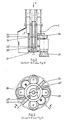
- Figure 4 shows the design of the lower drive part of the intermediate piece and a portion of the upper drive part in a sectional view.
- FIG. 5 shows the upper drive part, which is based on the intermediate piece and is transferred into the control block.
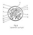
- FIG. 6 also shows the upper drive part in section DE from FIG. 5.
- Figure 7 shows the machine when using separately installed clamping nuts.
Die Innengewindereinigungsmaschine wird durch einen mit einem Hauptventil ausgerüsteten Steuerblock A beherrscht. Im Steuerblock A sind Druckluftanschlüsse A' zur Versorgung der Maschine mit Steuerluft, mit Arbeitsluft für den Antrieb des vorzugsweise als Druckluftlamellenmotor 8 ausgebildeten Antriebsmotors und zur Versorgung des Reinigungsbereiches mit Blasluft vorgesehen.The internal thread cleaning machine is controlled by a control block A equipped with a main valve. In control block A, compressed air connections A 'are provided for supplying the machine with control air, with working air for driving the drive motor, which is preferably designed as a compressed
Darüber hinaus ist dem Steuerblock A die Absaugeleitung A" sowie die Aufhängung für die Maschine verbunden. Des weiteren ist der Steuerblock A als Wartungseinheit für die Schmierung, Wasserabscheidung usw. ausgebildet, sowie mit Anschlüssen für eine pneumatische Fernbedienung A" der Maschine versehen.In addition, control block A is connected to suction line A "and the suspension for the machine. Furthermore, control block A is designed as a maintenance unit for lubrication, water separation, etc., and is provided with connections for pneumatic remote control A" of the machine.
Dem Steuerblock A schließt sich nach unten das zylindrische Gehäuse 17 des Antriebsoberteiles B an, wobei der Kopf 2 der Werkzeugträgerwelle 1 in einer gleichzeitig für die Blasluftzuführung 4 ausgebildeten Langlagerkombination 3 drehbar axial und radial geführt ist.The control block A is adjoined at the bottom by the
Der Werkzeugträgerwellenkopf 2 führt durch die Antriebsträgerplatte 5 und ist anschließend, d.h. darunter angeordnet, mit einem Stirnrad 6 formschlüssig verbunden, wobei in dieses Stirnrad 6 das ebenfalls unterhalb der Antriebsträgerplatte 5 achsparallel zur Werkzeugträgerwelle 1 angeordnete, durch einen auf der Antriebsträgerplatte 5 installierten Durckluftlamellenmotor 8 angetriebene Ritzel 7 eingreift.The tool
Des weiteren ist achsparallel zur Werkzeugträgerwelle 1 der Hubnocken 9 für den Eingriff einer Hubknagge 10 auf der Antriebsträgerplatte 5 vorgesehen, wobei diese ausschwenkbar mit dem Kopf der Kolbenstange 12 des Hubzylinders 11 verbunden ist und zunächst formschlüssig in den Hubnocken 9 greift. Die Antriebsträgerplatte 5 ist in achsparallel zur Werkzeugträgerwelle 1 angeordneten zylindrischen Säulen 13 geführt.Furthermore, the lifting
Die wesentlichen Teile des Antriebs sind über eine große verschließbare in dem Gehäuse 17 angeordneteThe essential parts of the drive are arranged in the
Die Inbetriebnahme erfolgt in aller Regel nach dem Einfahren des Antriebsunterteiles D (d.h. des Führungsrohres) in den RDB-Deckel, wobei zwischen Antriebsunterteil D und Antriebsoberteil B ein später beschriebenes Zwischenstück C geflanscht ist, das sich über den später beschriebenen Flansch 37 des Antriebsunterteiles D abstützt.Commissioning usually takes place after the lower drive part D (ie the guide tube) has been moved into the RPV cover, an intermediate piece C described later being flanged between the lower drive part D and the upper drive part B, which is supported via the
Die weitere Inbetriebnahme wird durch die Betätigung des Hubzylinders 11 bewirkt, der seinerseits wieder im Verlauf seines Hubes einen Rollenhebel 15 zur Betätigung des Wegeventilschalters "Motor-Start-Rechtslauf" und "Blasluft-Ein" veranlaßt. Der Hubzylinder 11 führt die Antriebsträgerplatte 5 so weit nach unten, bis der Bürstenkopf E in das Gewinde im RDB eingreift, wobei in dieser Lage der durch ein Gestänge 16 beherrschte Hubweg der Kolbenstange 12 des Hubzylinders 11 die Hubknagge 10 aus dem Hubnocken 9 ausschwenkt und damit die weitere Bewegung der Werkzeugträgerwelle 1 freigibt.The further commissioning is effected by the actuation of the lifting
Die Werkzeugträgerwelle 1 wird jetzt unabhängig vom Hubzylinder 11 durch Formschluß zwischen dem von ihr getragenen Bürstenkopf E mit dem zu reinigenden Gewinde nach unten bewegt, d.h. der Bürstenkopf E schraubt sich in das Gewinde ein.The
Der Einschraubweg des Bürstenkopfes E entspricht in aller Regel der Gewindelänge, wobei der Tiefstpunkt durch einen unteren Rollenhebel 15' zur Betätigung der Wegeventilschalter "Motor-Stop" und "Motor-Start-Linkslauf" bestimmt ist.The screw-in path of the brush head E generally corresponds to the thread length, the lowest point being determined by a lower roller lever 15 'for actuating the directional control valve switches "motor stop" and "motor start anticlockwise rotation".
Der Bürstenkopf E und damit die Werkzeugträgerwelle 1 schraubt sich nunmehr bis zur Wiedereinkupplung der Hubknagge 10 in den mit der Antriebsträgerplatte 5 verbundenen Hubnocken 9 hoch und der weitere nach oben gerichtete Rück transport wird bei Aufrechterhaltung der Drehung der Werkzeugträgerwelle 1 jetzt durch den jetzt nach oben ziehend en Hubzylinder 11 veranlaßt und zwar so lange, bis sich die Werkzeugträgerwelle 1 wieder in ihrer oberen Ausgangslage befindet und-der obere Rollenhebel 1 die Betätigung der Wegeventilschalter "Motor-Stop" und "Blasluft-Aus" ermöglicht.The brush head E and thus the
Um insbesondere beim Hochfahren des Bürstenkopfes E die Bürstenelemente durch das Gewicht der Antriebseinheit 8/5/6/7 usw., sowie der Werkzeugträgerwelle 1 und Teilen der Absaugevorrichtung zu entlasten, ist in dem zylindrischen Gehäuse 17 des Antriebsoberteiles B ein über Seilrollen 19 und 19' geführtes Gegengewicht 18 integriert, wobei die Lage des Gewichtes 18 innerhalb des Gehäuses 17 in dessen axialer Richtung durch Führungssäulen 18' fixiert ist. Hierbei ist je eine Seilrolle 19 mit dem oberen Abschlußflansch 20 des Gehäuses 17 und je eine Seilrolle 19' mit dem unteren Abschlußflansch 20' des Gehäuses 17 sowie mit dem Gegengewicht 18 über ein Seil 19"mit den zu entlastenden Teilen verbunden. Das Gegengewicht 18 ist ein die Antriebsteile, Abluftleitungen usw. aussparender Formkörper.In order to relieve the brush elements due to the weight of the
Zur Blasluftführung 4 ist zu bemerken, daß, wie eingangs erwähnt, diese in den durch die Langlagerkombination 3 gebildeten Ringraum 3' einmündet. Die Langlagerkombination 3 ist mit der Antriebsträgerplatte 5 verbunden. Der Kopf 2 der Werkzeugträgerwelle 1 ist in dieser Langlagerkombination 3 drehbar axial und radial geführt. Im Bereich zwischen den beiden Hauptführungslagern 3" wird die Druckluft über ein Steuerventil in den dort gegebenen Ringraum 3' geleitet und tritt durch radial gerichtete Bohrungen 21 in eine zentral durch den Werkzeugträgerwellenkopf 2 gerichtete Bohrung 22 ein, wobei der Kopf 2 in ein mit ihm verbundenes Präzisionsstahlrohr 23 überführt, das im wesentlichen die Werkzeugträgerwelle 1 bildet.Regarding the blown air duct 4, it should be noted that, as mentioned at the beginning, it opens into the annular space 3 'formed by the
Im unteren Bereich (D) führt die Werkzeugträgerwelle 1 in ein durch Flansch 25 begrenztes Endstück 24 über, wobei der Flansch 25 gleichzeitig Träger des Mantelrohres 26 für die später beschriebene Abluftzuführung ist. Die Werkzeugträgerwelle 1 ist im Zwischenstück C durch eine Kupplung 27 trennbar.In the lower region (D), the
Mit dem Flansch 25 ist der eigentliche Bürstenkopf E verbunden, der in der Regel vier radial gerichtete Rundbürsten 28 und zwei axial gegen den Gewindegrund im RDB gerichtete Tellerbürsten 29 aufweist. Die Führung der Luft erfolgt in diesem Bereich zentrisch. Die Blasluft tritt von hier aus radial in zwei übereinander angeordneten Ebenen vorgesehenen Ringkanäle 30 und 30', die im Bereich der radial gerichteten Rundbürsten 28 geöffnet sind, und über zusätzliche Richtdüsen 30" in die Gewindegänge ein. Die weiterführende axiale Fortsetzung dieser zentrSlen Blasluftzuführung verjüngt sich gegen das düsenförmig ausgebildete Ende, wobei dieses Ende 31 die Blasluft gegen den Grund des Sacklochgewindes des RDB führt.The actual brush head E is connected to the
Unabhängig von diesem Bürstenkopf E kann ein anderer Kopf aufgesetzt werden, wobei dieser aus mit dem Gewinde korrespondierenden Filzscheiben 40 besteht, die in der Regel mit Molykote getränkt sind.Regardless of this brush head E, another head can be put on, this one consists of felt disks 40 corresponding to the thread, which are generally impregnated with molykote.
Die Absaugung dient der Entfernung der aus den Gewindegängen abgereinigten Schmutzpartikel und sie schließt am Steuerblock A an und führt im weiteren durch das zylindrische Gehäuse 17 des Antriebsoberteiles B, durch das Zwischenstück C, durch das als Führungsrohr ausgebildete Antriebsunterteil D und mündet von dort in das die Werkzeugträgerwelle 1 umfassende Absaugemantelrohr 26, um letztlich in zwei mit dem Bürstenkopf E und der Werkzeugträgerwelle 1 verbundene Absaugehutzen 32 einzumünden.The suction serves to remove the dirt particles cleaned from the threads and it connects to the control block A and leads further through the
Die Anordnung bzw. die Befestigung des Absaugemantelrohres 26 an dem unteren Endflansch 25 der Werkzeugträgerwelle 1 wurde bereits beschrieben. Das sich drehende Absaugemantelrohr 26 mündet in Absaugerichtung in dem Antriebsunterteil D in eine in ihrer axialen Richtung verschiebbar einstellbaren, jedoch sich nicht drehenden Abluftsammelkammer 33 - und zwar gegen diese abdichtend - ein. Die eigentliche Werkzeugträgerwelle 1 führt im weiteren Durchgang durch diese Kammer 33 und tritt aus dieser gemeinsam mit der Kammer 33 axial verschiebbar und gegen diese abgedichtet, aus.The arrangement or the attachment of the
Mit der Abluftsammelkammer 33 sind feststehende Absaugerohre 34 verbunden, von denen im weiteren Verlauf nach oben führend jedes als Teleskopzug 35 ausgebildet ist. Die Rohre enden in dem unteren Begrenzungsflansch 36 des zum Antriebsoberteil B führenden Zwischenstückes C. Das Zwischenstück C baut auf einem einseitig klauenförmig ausgebildeten Flansch 37 auf, wobei dieser als Drehmomentenstütze gegen den RDB-Deckel wirksam ist.
In aller Regel führen zwei Absaugerohre 34 von der Abluftsammelkammer 33 durch das Antriebsunterteil D in das Zwischenstück C. Der jeweils einmündende Bereich des jeweiligen Absaugerohres 34 ist über eine lösbare Schlauchverbindung 38 mit dem jeweils durch das Antriebsoberteil B führenden Absaugerohr 34' verbunden.As a rule, two
Ebenfalls ist in dem Zwischenstück C durch die Kupplung 27 das Oberteil der Werkzeugträgerwelle 1 von dessen Unterteil trennbar. Das Zwischenstück C ist mit einem Montagedeckel 39 versehen, so daß von hier aus die Werkzeugträgerwelle 1 getrennt und Austauschteile installiert werden können. Des weiteren können die Schlauchverbindungen 38 der Absaugerohre 34 / 34' entfernt werden, so daß von hier aus jedes Absaugerohr 34, - z.B. durch;Ausstoßen mit geeigneten Hilfsmitteln, gereinigt werden kann. Die Absaugerohre 34' werden führend durch B und A dem Werknetz angeschlossen und die aboesaugte Luft in geeigneten Filtern gereinigt.In the intermediate piece C, the upper part of the
Die Reinigung von demontierten Muttern auf einem separaten Abstellring ist ebenfalls mit dieser Maschine möglich. In diesem Fall wird die flexible Absaugleitung am Steuerblock A abgebaut. Die Absaugung erfolgt dann über einen über die Mutter greifenden Adapter 41, dem nach unten eine modifizierte Absaugeleitung 42, die ebenfalls zu einem Filtergerät führt,angeschlossen ist. Die Belüftung der Arbeitsstelle erfolgt hier über die freigelegten Absaugleitungen.This machine can also be used to clean dismantled nuts on a separate parking ring. In this case, the flexible suction line on control block A is removed. The suction then takes place via an
Bei Ausfall des Druckluftlamellenmotors 8 bei eingefahrenem Bürstenkopf E kann von der Arbeitsbühne aus eingegriffen werden. Für diesen Zweck ist ein zweites in das Stirnrad 6 eingreifendes, lose mitlaufendes Ritzel 7' vorgesehen, das mit einem durch die Antriebsträgerplatte 5 greifenden Vierkantansatz 7" Arbeitsbühne anzusetzende Handkurbel antreibbar. Der Bürstenkopf E kann damit manuell zurückgeschraubt werden.If the compressed
Claims (6)
Applications Claiming Priority (2)
| Application Number | Priority Date | Filing Date | Title |
|---|---|---|---|
| DE3135882 | 1981-09-10 | ||
| DE19813135882 DE3135882C2 (en) | 1981-09-10 | 1981-09-10 | Device for cleaning blind hole threads in reactor pressure vessels (RPV) with the reactor cover removed or on |
Publications (3)
| Publication Number | Publication Date |
|---|---|
| EP0075155A2 EP0075155A2 (en) | 1983-03-30 |
| EP0075155A3 EP0075155A3 (en) | 1983-07-27 |
| EP0075155B1 true EP0075155B1 (en) | 1986-04-09 |
Family
ID=6141322
Family Applications (1)
| Application Number | Title | Priority Date | Filing Date |
|---|---|---|---|
| EP19820108082 Expired EP0075155B1 (en) | 1981-09-10 | 1982-09-02 | Method of cleaning blind hole threads in reactor pressure vessels with removed or mounted reactor covers by means of a cleaning machine, and machine for carrying out this method |
Country Status (2)
| Country | Link |
|---|---|
| EP (1) | EP0075155B1 (en) |
| DE (1) | DE3135882C2 (en) |
Families Citing this family (6)
| Publication number | Priority date | Publication date | Assignee | Title |
|---|---|---|---|---|
| DE3332881A1 (en) * | 1983-09-13 | 1985-03-28 | Nico Industriereinigung AG, Luzern | METHOD AND DEVICE FOR DECONTAMINATING RADIOACTIVELY DIRTED METAL PROFILES |
| DE19509019C2 (en) * | 1995-03-13 | 1997-03-27 | Siemens Ag | Device for machining a threaded blind hole |
| DE102018118136B3 (en) * | 2018-07-26 | 2019-10-10 | Siempelkamp NIS Ingenieurgesellschaft mbH | Scraper head and scraper cleaning |
| DE102018118145B4 (en) * | 2018-07-26 | 2020-08-06 | Siempelkamp NIS Ingenieurgesellschaft mbH | Brush head, cover screw connection and method for cleaning an internal thread of a cover screw connection |
| DE102018118131B3 (en) * | 2018-07-26 | 2019-11-07 | Siempelkamp NIS Ingenieurgesellschaft mbH | Cleaning device and method for cleaning an internal thread of a cover screw connection of a reactor pressure vessel |
| CN111843586A (en) * | 2020-08-18 | 2020-10-30 | 苏州麻雀智能科技有限公司 | Intelligent manufacturing unit of machine tool |
Family Cites Families (6)
| Publication number | Priority date | Publication date | Assignee | Title |
|---|---|---|---|---|
| DE1657181A1 (en) * | 1968-02-09 | 1971-02-11 | Willi Leise | Device for cleaning beer glasses |
| SE400024B (en) * | 1976-02-11 | 1978-03-13 | Wennberg Flex Ake Ab | SUCTION DEVICE FOR DIRECT EVACUATION OF POLLUTANTS FROM POLLUTIONING TOOLS IN A WORKPLACE |
| DE2606214C3 (en) * | 1976-02-17 | 1980-11-27 | Lothar A. 7141 Hochdorf Voigt | Device for cleaning the threads of screw bolts |
| FR2355578A1 (en) * | 1976-06-23 | 1978-01-20 | Rousselin Jean | Suction cleaner for removing surface deposits in nuclear reactors - which incorporates rotary tool and bell and is economical in space and power |
| DE2732882C3 (en) * | 1977-07-21 | 1980-05-22 | Ntg Nukleartechnik Gmbh U. Partner, 6460 Gelnhausen | Device for cleaning the internal thread of nuts |
| DE2948006A1 (en) * | 1979-11-29 | 1981-06-04 | Jürgen 4477 Welver Volkmann | METHOD AND DEVICE FOR REMOVING SOLID OR LIQUID RESIDUES FROM CAVITIES LIKE HOLES OR THE LIKE. |
-
1981
- 1981-09-10 DE DE19813135882 patent/DE3135882C2/en not_active Expired
-
1982
- 1982-09-02 EP EP19820108082 patent/EP0075155B1/en not_active Expired
Also Published As
| Publication number | Publication date |
|---|---|
| DE3135882C2 (en) | 1984-12-20 |
| DE3135882A1 (en) | 1983-03-31 |
| EP0075155A2 (en) | 1983-03-30 |
| EP0075155A3 (en) | 1983-07-27 |
Similar Documents
| Publication | Publication Date | Title |
|---|---|---|
| DE3688169T2 (en) | FREE MOVABLE CLEANING DEVICE FOR TUBE BUNDLE. | |
| DE69621585T2 (en) | DEVICE FOR REPLACING BURNERS | |
| EP1785222B1 (en) | Quick-action coupling cylinder comprising a guiding device for the nipple | |
| DE3421885C2 (en) | Process for cleaning the gas nozzle of a welding torch and device for carrying out the process | |
| EP0878241A2 (en) | Installation for collecting excess powder in powder coating of workpieces | |
| DE1298952B (en) | Device for assembling and disassembling pipes or pipe bundles in elongated housings, especially for heat exchangers | |
| DE2831687A1 (en) | DEVICE FOR CLEANING THE UPPER PIPES OF COOK OVEN BATTERIES | |
| DE102014011133A1 (en) | Centrifugal station and compressed air cleaning arrangement | |
| EP0075155B1 (en) | Method of cleaning blind hole threads in reactor pressure vessels with removed or mounted reactor covers by means of a cleaning machine, and machine for carrying out this method | |
| DE202008017291U1 (en) | Cleaning device for Lukos or the like. heat exchangers | |
| DE3142849C2 (en) | ||
| CH656151A5 (en) | ANODE ROD CLEANING MACHINE. | |
| EP0130373A2 (en) | Method and apparatus for repairing valve spindles | |
| DE69000540T2 (en) | DEVICE FOR CLEANING BUILDING FACADES. | |
| EP0172556B1 (en) | Spinning apparatus for man-made fibres containing a shaft with a telescopic superior part | |
| DE3730438C2 (en) | ||
| DE68928623T2 (en) | FILTRATION DEVICE CONTAINING A PUMP | |
| DE2606214A1 (en) | Cleaning reactor vessel top closure bolts - by remotely controlled rotating brush assembly revolving around bolt | |
| WO2012163993A2 (en) | Apparatus for cleaning surfaces | |
| DE102021121654B3 (en) | Pump device, method for carrying out a service on a pump device | |
| AT393687B (en) | DEVICE FOR CLEANING THE DOORS OF COOKING OVEN BATTERIES | |
| DE3439653C1 (en) | Device for connecting a drill string to a pipe or the like. | |
| DE2500067A1 (en) | Rake cleaner for clarification plant inlet - has hydraulically actuated rake fitted on rake carriage | |
| DE2423210C3 (en) | Peeling machine for bars and tubes with a back and forth movable clamping carriage | |
| DE3223727C2 (en) | Lift drive device for gripper rake |
Legal Events
| Date | Code | Title | Description |
|---|---|---|---|
| PUAI | Public reference made under article 153(3) epc to a published international application that has entered the european phase |
Free format text: ORIGINAL CODE: 0009012 |
|
| AK | Designated contracting states |
Designated state(s): BE CH FR GB IT LI SE |
|
| PUAL | Search report despatched |
Free format text: ORIGINAL CODE: 0009013 |
|
| AK | Designated contracting states |
Designated state(s): BE CH FR GB IT LI SE |
|
| 17P | Request for examination filed |
Effective date: 19840127 |
|
| GRAA | (expected) grant |
Free format text: ORIGINAL CODE: 0009210 |
|
| AK | Designated contracting states |
Kind code of ref document: B1 Designated state(s): BE CH FR GB IT LI SE |
|
| ITF | It: translation for a ep patent filed | ||
| ET | Fr: translation filed | ||
| RAP2 | Party data changed (patent owner data changed or rights of a patent transferred) |
Owner name: NTG NUKLEARTECHNIK GMBH & CO. KG |
|
| BECN | Be: change of holder's name |
Effective date: 19861001 |
|
| PLBI | Opposition filed |
Free format text: ORIGINAL CODE: 0009260 |
|
| 26 | Opposition filed |
Opponent name: KRAFTWERK UNION AKTIENGESELLSCHAFT Effective date: 19870108 |
|
| REG | Reference to a national code |
Ref country code: CH Ref legal event code: PFA Free format text: NTG NEUE TECHNOLOGIEN GMBH & CO. KG |
|
| RAP2 | Party data changed (patent owner data changed or rights of a patent transferred) |
Owner name: NTG NEUE TECHNOLOGIEN GMBH & CO. KG |
|
| PLAB | Opposition data, opponent's data or that of the opponent's representative modified |
Free format text: ORIGINAL CODE: 0009299OPPO |
|
| PLAB | Opposition data, opponent's data or that of the opponent's representative modified |
Free format text: ORIGINAL CODE: 0009299OPPO |
|
| R26 | Opposition filed (corrected) |
Opponent name: SIEMENS AKTIENGESELLSCHAFT, BERLIN UND MUENCHEN Effective date: 19870108 |
|
| R26 | Opposition filed (corrected) |
Opponent name: SIEMENS AKTIENGESELLSCHAFT, BERLIN UND MUENCHEN Effective date: 19870108 |
|
| PG25 | Lapsed in a contracting state [announced via postgrant information from national office to epo] |
Ref country code: LI Effective date: 19890930 Ref country code: CH Effective date: 19890930 Ref country code: BE Effective date: 19890930 |
|
| PLBN | Opposition rejected |
Free format text: ORIGINAL CODE: 0009273 |
|
| STAA | Information on the status of an ep patent application or granted ep patent |
Free format text: STATUS: OPPOSITION REJECTED |
|
| 27O | Opposition rejected |
Effective date: 19890806 |
|
| BERE | Be: lapsed |
Owner name: NTG NEUE TECHNOLOGIEN G.M.B.H. & CO. K.G. Effective date: 19890930 |
|
| PG25 | Lapsed in a contracting state [announced via postgrant information from national office to epo] |
Ref country code: FR Effective date: 19900531 |
|
| REG | Reference to a national code |
Ref country code: CH Ref legal event code: PL |
|
| REG | Reference to a national code |
Ref country code: FR Ref legal event code: ST |
|
| PGFP | Annual fee paid to national office [announced via postgrant information from national office to epo] |
Ref country code: SE Payment date: 19900925 Year of fee payment: 9 |
|
| PGFP | Annual fee paid to national office [announced via postgrant information from national office to epo] |
Ref country code: GB Payment date: 19901012 Year of fee payment: 9 |
|
| PG25 | Lapsed in a contracting state [announced via postgrant information from national office to epo] |
Ref country code: GB Effective date: 19910902 |
|
| PG25 | Lapsed in a contracting state [announced via postgrant information from national office to epo] |
Ref country code: SE Effective date: 19910903 |
|
| GBPC | Gb: european patent ceased through non-payment of renewal fee | ||
| EUG | Se: european patent has lapsed |
Ref document number: 82108082.7 Effective date: 19920408 |