EP0075064B1 - Abrading device for a brake disc - Google Patents
Abrading device for a brake disc Download PDFInfo
- Publication number
- EP0075064B1 EP0075064B1 EP82102824A EP82102824A EP0075064B1 EP 0075064 B1 EP0075064 B1 EP 0075064B1 EP 82102824 A EP82102824 A EP 82102824A EP 82102824 A EP82102824 A EP 82102824A EP 0075064 B1 EP0075064 B1 EP 0075064B1
- Authority
- EP
- European Patent Office
- Prior art keywords
- brake disc
- bracket
- abrading device
- pair
- abrading
- Prior art date
- Legal status (The legal status is an assumption and is not a legal conclusion. Google has not performed a legal analysis and makes no representation as to the accuracy of the status listed.)
- Expired
Links
Images


Classifications
-
- B—PERFORMING OPERATIONS; TRANSPORTING
- B24—GRINDING; POLISHING
- B24B—MACHINES, DEVICES, OR PROCESSES FOR GRINDING OR POLISHING; DRESSING OR CONDITIONING OF ABRADING SURFACES; FEEDING OF GRINDING, POLISHING, OR LAPPING AGENTS
- B24B7/00—Machines or devices designed for grinding plane surfaces on work, including polishing plane glass surfaces; Accessories therefor
- B24B7/10—Single-purpose machines or devices
- B24B7/16—Single-purpose machines or devices for grinding end-faces, e.g. of gauges, rollers, nuts, piston rings
- B24B7/17—Single-purpose machines or devices for grinding end-faces, e.g. of gauges, rollers, nuts, piston rings for simultaneously grinding opposite and parallel end faces, e.g. double disc grinders
-
- B—PERFORMING OPERATIONS; TRANSPORTING
- B24—GRINDING; POLISHING
- B24B—MACHINES, DEVICES, OR PROCESSES FOR GRINDING OR POLISHING; DRESSING OR CONDITIONING OF ABRADING SURFACES; FEEDING OF GRINDING, POLISHING, OR LAPPING AGENTS
- B24B23/00—Portable grinding machines, e.g. hand-guided; Accessories therefor
- B24B23/08—Portable grinding machines designed for fastening on workpieces or other parts of particular section, e.g. for grinding commutators
Definitions
- This invention relates to an abrading device (or an abrader), and more particularly, it is concerned with a device for abrading the frictional surface of a brake disc of an automobile provided with a disc-type brake on its wheels, when the brake disc gets rusted or stained with oil on its surface.
- the invention also relates to a device for improving working precision in the abrading device for the automobile brake disc.
- an abrading device which, for avoiding trouble and complicacy in removing the brake disc from the axle at every time the brake disc is to be abraded, performs abrasion by urging a grinding stone to the frictional surface of the brake disc with its being mounted on the axle, and rotating the brake disc by an appropriate power source such as automobile engine, while the grinding stone is also being rotated so as not to cause scratches due to cutting by the grinding stone to appear on the frictional surface of the brake disc.
- the abovementioned conventional abrading device for the brake disc provides a fitting member for equipping the abrading device on the caliper supporting member and the supporting member for the grinder with respect to the fitting member being of a cantilever type, with the consequence that the grinding surface of the grinding stone cannot be maintained in a mutually parallel manner with the frictional surface of the brake disc so as to bring about unilateral contact between them, which thereby gives rise to scratches on the frictional surface of the brake disc.
- EP-A-0 006 764 describes an abrading device for vehicle brake discs having a bracket being substantially parallel to said disc mounted on an axle and being provided for the mounting of brake calipers.
- a pair of bearing frames are slidably mounted on a guide rod parallel to said axle.
- a pair of grinding stones one each held on said bearing frames hold said brake disc from its both surfaces. Grinding stone urging means hold the grinding stones in frictional contact with the brake disc.
- an improved abrading device for a brake disc of an automobile is capable of automatically performing cutting of the grinding stone to a predetermined degree.
- Such an improved abrading device for a brake disc of an automobile should make it possible for an operator of the device to know the termination of the cutting work by an electrical signal.
- an improve abrading device for a brake disc is provided with means aiming at increasing precision in the abrasion work by permitting horizontal deflection of the grinding stone following the surface of the brake disc within a certain predetermined limit through appropriate setting of a sliding resistance between the supporting cylinder of a bracket and a guide rod, thereby attempting to maintain uniform wear of the grinding stone on both sides of the brake disc.
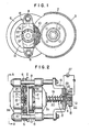
- the abrading device of the present invention is constructed with an axle 1 of the automobile, a brake disc 2 (hereinafter simply called “disc"), a disc cover 3, a caliper supporting member 4, a knuckle 5, and a substantially horse-shoe-shaped bracket 6 being fitted by bolts 7, 7 in a manner to be substantially parallel with the disc 2 and to protrude toward the outer periphery of the disc 2 by utilizing bolt holes remaining free after removal of the caliper from the caliper supporting member 4.
- the abovementioned guide rods 8, 8 support thereon bearing frames 9a, 9b at both the left and the right side of the substantially horse-shoe-shaped bracket 6 (vide Figure 2).
- the guide rods 8, 8 pass through both end parts of the bearing frame 9a, 9b, one of the bearing frames (9a) being fixed at one end of the guide rods 8, 8, and the other of the bearing frames (9b) being slidable along the guide rods 8, 8.
- Grinding stones 10, 10 are rotatably mounted on the opposing surfaces of the abovementioned bearing frames 9a, 9b through the shafts 11, 11.
- the rear surface of each grinding stone 10 is received on and held by a flange 12 having substantially the same diameter as the grinding stone.
- reference numeral 13 designates a cover for the grinding stone
- numeral 14 refers to a stopper flange for the grinding stone
- 15 designates a fixing bolt for the grinding stone.
- the end parts of the guide rods 8, 8 at the side of supporting the movable bearing frame 9b are joined with a fixed frame 16. Between the fixed frame 16 and the movable bearing frame 9b, there is provided a grinding stone urging device A for the cutting (abrading) operation.
- the urging device A may be either a manually operating means provided only with a tightening screw mechanism (i.e., a screw 17 and a pushing rod 18) as shown in Figure 4, or an automatic urging means as shown in Figure 2 utilizing a compression coil spring 19 or a tensile force of a dish spring.
- the automatic urging device A in Figure 2 is provided with means B for setting an abrading quantity, i.e., a moving quantity of the grinding stone.
- a supporting rod 20 for the coil spring 19 compressed between the movable bearing frame 9b and the fixed frame 16 extends outwardly through the fixed frame 16.
- the base part of the nut 21 is loosely fitted around the fixed frame 16.
- Electrical contacts 25, 26 are provided on the opposite surfaces of the fixed frame 16 and the nut 21, both of which are connected to a signalling apparatus 27 such as a pilot lamp, buzzer, bell, and so on.
- a brake caliper (not shown in the drawing) is removed from the caliper supporting member 4 and the nut 21 is turned to the left (vide: the embodiments shown in Figures 1 and 2) to thereby cause the bearing part 9b to retreat against force of a spring 19 and widen the space gap between the grinding stones 10, 10 and the brake disc 2.
- a screw rod 17 is turned to the left to directly pull the bearing frame 9b backward, thereby widening the gap between the grinding stones and the brake disc.
- the screw rod 17 is turned to the right so as to tighten it while continuing to urge the frictional surface of the brake disc with the grinding stones 10, 10, the abrading quantity of which is verified by monitoring with eyes. As soon as the required quantity of abrasion has been attained, the screw rod 17 is reversely turned to separate the grinding stones 10, 10 from the brake disc 2.
- each of the bearing frames 9a, 9b by fixing together the guide rods 8, 8 and the substantially horse-shoe-shaped bracket 6, and then slidably supporting the bearing frames 9a, 9b on the guide rods 8, 8.
- the abrading device for the brake disc is of such a construction that the substantially horse-shoe-shaped bracket 6 mounted on the caliper supporting member 4 of the automobile in a manner to be interchangeable with the caliper is protruded toward the outer periphery of the brake disc 2 substantially in parallel with the brake disc on the axle 1; then, at the outer periphery of the brake disc 2, there are provided a pair of bearing frames 9a, 9b, which are supported on the above- mentioned horse-shoe-shaped bracket 6, at least one of which is slidably supported on the above- mentioned substantially horse-shoe shaped bracket 6; the grinding stones 10, 10 are rotatably supported on the abovementioned bearing frame 9a, 9b in a manner to hold the brake disc 2 at both surfaces; and the grinding stone urging means A to the brake disc 2 is provided between the bearing frame 9b and the guide rod 8.
- the caliper supporting member 4to hold the grinding stones 10, 10 on both surfaces of the brake disc 2 in a manner to contact thereto, the substantially horse-shoe-shaped bracket 6, the guide rods 8, 8, the bearing frames 9a, 9b, and so forth are mutually supported at two points.
- a reference numeral 12 designates the grinding stone receiving and holding member integral with the shaft 11
- numeral 14 refers to the stopper for the grinding stone
- numeral 15 indicates a stopper screw.
- the grinding stone urging means A is constructed as an automatically operable means utilizing the force of the spring, to which there is additionally provided means B for presetting an abrading quantity, so that, if only the means B is manipulated beforehand, there follows automatic abrasion for the quantity set.
- the device is so constructed that, as soon as the abovementioned abrasion completes, a notifying signal may be emitted, hence there is no necessity for watching the abrading quantity of the brake disc 2 with eyes, which effectively contributes to improving the working efficiency.
- the fixed frame 16 is fitted between the pair of the guide rods 8, 8, to which the pushing screw rod 18 to be gradually advanced by the manually operated knob 17a through the screw 17 is supported, then one of the bearing frames 9b is pushed in the axial direction of the grinding stone, and, at the same time, the other bearing frame 9a is pulled toward the bearing frame 9b, thereby performing the cutting of the brake disc 2 by the grinding stones 10, 10.
- the embodiment illustrated in Figure 6 is of such a construction that the feeder 30 is rotatably fitted in the hole of the fixed frame 16, that the above- mentioned knob 17a is fixed to the feeder 30 with the pushing screw 17b, and that the screw 17 of the pushing guide rod 18 is screwed in the hole of the feeder.
- Reference numeral 32 designates a metal
- numeral 34 refers to a thrust bearing.
- rust does not uniformly develop on the brake disc 2 over its entire surface. In most cases, it develops in local places, and, in particular, as shown in the side view of Figure 2, it sometimes develops and adheres onto its surface in a wavy shape. In such case, when the sliding resistance of the guide rod 8 to the guide rod holding cylinder of the bracket 6 is too small, both grinding stones 10, 10 deflect to the left and right following the wavy surface of the disc brake 2, and its abrading efficiency is low. Although the deflection depends on the magnitude of the sliding resistance, it is governed by the weight of the movable part as a whole.
- stepwise or cascaded holes 36, 38, 40 are formed inside the push rod 18 in its longitudinal direction, through which holes a spring receiving and holding rod 42 is inserted in such a manner that it may move forward and backward in and along the long hole 44 and without rotation avoided by a rotation stopping pin 46.
- a pushing knob 48 is fixed on the outer end part of the spring receiving and holding rod 42, and a coil spring 50 is accommodated in a space defined between the inner end of the pushing knob 48 and a stage 38a of the hole 38.
- Numeral 52 refers to graduations inscribed in the outer periphery of the pushing knob 48.
- a sleeve 54 is interposed between the holding cylinder 6a and a guide rod 8, and a degree of pressure contact to the guide rod 8 of the sleeve 54 is adjusted to regulate the sliding resistance between the guide rod 8 and the holding cylinder 6a.
- a rotation stopper is provided between the supporting cylinder 6a and the sleeve 54.
- a reference numeral 58 designates an 0-ring
- numeral 60 refers to a snap ring
- numeral 62 denotes a ring to stop a flange 18a at the forward end part of the pushing rod 18
- 64 designates a fitting bolt for the stopper ring 62.
- the sliding resistance of the sleeve 54 to the guide rod 8 is established by the pushing screw 56, through reading of a numerical value from the graduations 52 inscribed on the outer periphery of the pushing knob 48 at the start of its moving, in such a manner that the value as read out may substantially coincide with a value previously found by a test machine.
Abstract
Description
- This invention relates to an abrading device (or an abrader), and more particularly, it is concerned with a device for abrading the frictional surface of a brake disc of an automobile provided with a disc-type brake on its wheels, when the brake disc gets rusted or stained with oil on its surface. The invention also relates to a device for improving working precision in the abrading device for the automobile brake disc.
- In recent years, a disc-type brake has been widely adopted as the braking device for automobiles. Since, however, this type of the brake inevitably exposes the contact surface between the brake-disc and the brake shoe to the external air, it readily gets rusted on the surface thereof when it is left unused for one to two months, particularly in a cold district where salt is dispersed on the road as a non-freezing measure, with the consequence that smooth braking action becomes difficult to achieve. Therefore, it is highly desirable that, before the vehicle is actuated, the rust is removed and necessary adjustment is effected.
- For this purpose, there has already been known an abrading device which, for avoiding trouble and complicacy in removing the brake disc from the axle at every time the brake disc is to be abraded, performs abrasion by urging a grinding stone to the frictional surface of the brake disc with its being mounted on the axle, and rotating the brake disc by an appropriate power source such as automobile engine, while the grinding stone is also being rotated so as not to cause scratches due to cutting by the grinding stone to appear on the frictional surface of the brake disc.
- There has also been known a structure, in which the abrading device is fitted by utilizing a caliper supporting member in a manner to be interchangeable with the caliper so that the abovementioned abrading device may be set in the neighborhood of the disc brake of the automobile at the time of abrading the brake disc.
- However, the abovementioned conventional abrading device for the brake disc provides a fitting member for equipping the abrading device on the caliper supporting member and the supporting member for the grinder with respect to the fitting member being of a cantilever type, with the consequence that the grinding surface of the grinding stone cannot be maintained in a mutually parallel manner with the frictional surface of the brake disc so as to bring about unilateral contact between them, which thereby gives rise to scratches on the frictional surface of the brake disc.
- Incidentally, there has been known so far most generally: (1) a method for removing the brake disc from the automobile for abrasion; and (2) a method for abrading the brake disc by fitting the abrading device in place of the brake shoe, and rotating the grinding stone, utilizing the rotation of the automobile engine as a drive power source.
- With a view to attaining smooth braking action, very stringent requirements are imposed on the brake disc such as its surface smoothness, precision in its deflection, gauge, and so forth, hence the abrading device is required to be highly precise in its construction and operation.
- While the precision in the disc per se can be secured, in the above-mentioned method not only the precision of the same in its state of being mounted on the axle is not guaranteed, but also the abrading device as a whole becomes expensive, and, moreover, much time is required for the brake disc to be removed from and mounted on the automobile axle, which results in a loss in economy. The method (2) suffers from the same problem as mentioned above in respect of its precision, even though the rust can be removed perfectly.
- EP-A-0 006 764 describes an abrading device for vehicle brake discs having a bracket being substantially parallel to said disc mounted on an axle and being provided for the mounting of brake calipers. A pair of bearing frames are slidably mounted on a guide rod parallel to said axle. A pair of grinding stones one each held on said bearing frames hold said brake disc from its both surfaces. Grinding stone urging means hold the grinding stones in frictional contact with the brake disc.
- In view of such various problems inherent in the conventional abading devices as mentiond in the foregoing, it is a primary object of the present invention to provide an improved abrading device for a brake disc of an automobile, which is capable of accurately press-contacting the grinding stone and brake disc, even when the device is mounted on the caliper supporting member of the automobile in a manner interchangeable with the caliper.
- This object is achieved by the features of the claims.
- According to one embodiment of the present invention an improved abrading device for a brake disc of an automobile is capable of automatically performing cutting of the grinding stone to a predetermined degree.
- Such an improved abrading device for a brake disc of an automobile should make it possible for an operator of the device to know the termination of the cutting work by an electrical signal.
- According to another embodiment of the present invention an improve abrading device for a brake disc is provided with means aiming at increasing precision in the abrasion work by permitting horizontal deflection of the grinding stone following the surface of the brake disc within a certain predetermined limit through appropriate setting of a sliding resistance between the supporting cylinder of a bracket and a guide rod, thereby attempting to maintain uniform wear of the grinding stone on both sides of the brake disc.
- There has thus been outlined, rather broadly, the more important feature of the present invention so that the detailed description thereof that follows may be better understood, and that the present contribution to the art may be better appreciated. There are, of course, additional features of the invention that will be described hereinafter and which will form the subject of the claims appended hereto. Those skilled in the art will appreciate that the concept upon which this disclosure is based may readily be utilized as a basis for the designing of other structures for carrying out the several purposes of the present invention. It is important, therefore, that the claims be regarded as including such equivalent construction as far as they do not depart from the spirit and scope of the present invention.
- Specific embodiments of the present invention have been chosen for the purpose of illustration and description, and are shown in the accompanying drawing, forming a part of the specification, in which:
- Figure 1 is a front view showing the abrading device of the present invention in the state of its use;
- Figure 2 is a side elevational view of the abrading device, when viewed from its left side;
- Figure 3 is a rear view of the same abrading device;
- Figure 4 is a front view of the main part of the embodiment according to the present invention constructed in a manual cutting type;
- Figure 5 is a side elevational view, partly in longitudinal cross-section, of the abrading device according to the present invention;
- Figure 6 is an enlarged side elevational view, partly in longitudinal cross-section showing a principal part of the manual cutting construction according to the present invention; and
- Figure 7 is an enlarged side view, partly in longitudinal cross-section, of a sliding resistance adjusting mechanism with respect to a guide rod.
- In the following, the construction of the abrading device according to the present invention will be described in specific details with reference to its preferred embodiments as shown in the accompanying drawing.
- Referring first to Figures 1 to 3, the abrading device of the present invention is constructed with an axle 1 of the automobile, a brake disc 2 (hereinafter simply called "disc"), a disc cover 3, a
caliper supporting member 4, aknuckle 5, and a substantially horse-shoe-shaped bracket 6 being fitted bybolts disc 2 and to protrude toward the outer periphery of thedisc 2 by utilizing bolt holes remaining free after removal of the caliper from thecaliper supporting member 4. - On the outer periphery of the
disc 2, there are slidably supported a pair of upper andlower guide rods shaped bracket 6. - The
abovementioned guide rods frames guide rods frame guide rods guide rods - Grinding
stones frames stone 10 is received on and held by aflange 12 having substantially the same diameter as the grinding stone. Incidentally,reference numeral 13 designates a cover for the grinding stone,numeral 14 refers to a stopper flange for the grinding stone, and 15 designates a fixing bolt for the grinding stone. - The end parts of the
guide rods frame 9b are joined with a fixedframe 16. Between thefixed frame 16 and the movable bearingframe 9b, there is provided a grinding stone urging device A for the cutting (abrading) operation. The urging device A may be either a manually operating means provided only with a tightening screw mechanism (i.e., ascrew 17 and a pushing rod 18) as shown in Figure 4, or an automatic urging means as shown in Figure 2 utilizing acompression coil spring 19 or a tensile force of a dish spring. The automatic urging device A in Figure 2 is provided with means B for setting an abrading quantity, i.e., a moving quantity of the grinding stone. - A supporting
rod 20 for thecoil spring 19 compressed between the movable bearingframe 9b and thefixed frame 16 extends outwardly through thefixed frame 16. At the end part of the supportingrod 20, there is screwed an abradingquantity setting nut 21 by a left-threadedscrew 22. The base part of thenut 21 is loosely fitted around thefixed frame 16. -
Graduations 23 indicating the abrading quantity in its peripheral direction on the surface of the fixed frame facing thenut 21 and anindex 24 to thedial 23 are provided on the nut in correspondence to thedial 23. -
Electrical contacts fixed frame 16 and thenut 21, both of which are connected to asignalling apparatus 27 such as a pilot lamp, buzzer, bell, and so on. - In the following, operations of the abrading device according to the present invention will be explained. A brake caliper (not shown in the drawing) is removed from the
caliper supporting member 4 and thenut 21 is turned to the left (vide: the embodiments shown in Figures 1 and 2) to thereby cause the bearingpart 9b to retreat against force of aspring 19 and widen the space gap between thegrinding stones brake disc 2. - In the embodiment of Figure 4 a
screw rod 17 is turned to the left to directly pull the bearingframe 9b backward, thereby widening the gap between the grinding stones and the brake disc. - Subsequently, the tip end parts of both legs in the substantially horse-shoe shaped
bracket 6 are overlaid on one surface side of thecaliper supporting member 4, and fixed thereonto withbolts frame 9b until thegrinding stones brake disc 2. Following this, when thebrake disc 2 is rotated, thegrinding stones disc 2 due to friction between them (it may be feasible to impart rotational drive power to the grinding stones), in which state the forwarding motion for cutting is applied to thegrinding stones - That is to say, in the case of the manual operation of the abrading device as shown in Figure 4, the
screw rod 17 is turned to the right so as to tighten it while continuing to urge the frictional surface of the brake disc with thegrinding stones screw rod 17 is reversely turned to separate thegrinding stones brake disc 2. - In the automatic operation as shown in Figures 1 and 2, the
nut 21 is in contact with thefixed frame 16 by the tensile force of thespring 19 until thegrinding stones brake disc 2. In this state, when thenut 21 is further turned to the right, it begins to retreat owing to inability of the bearingframe 9b and the supportingrod 20 to move forward any more with the consequence that a gap g is formed between thenut 21 and thefixed frame 16, as shown in Figure 2. This gap g stands for the quantity of cutting, i.e., abrasion, by the grinding stones, the distance being represented bycircumferential graduations 23 in terms of pitch of thescrew 22. Accordingly, by turning thenut 21 until theindex 24 on it achieves a required value on thegraduations 23, there can be established a gap g corresponding to a quantity of cutting which an operator is intending to perform. In this state, when thebrake disc 2 rotates, thegrinding stones spring 19 until thenut 21 comes into contact with thefixed frame 16. In other words, both surfaces of thebrake disc 2 are automatically abraded by g/2 on each surface. Mutual contact ofcontact points - Incidentally, it is also feasible to provide the urging means on each of the
bearing frames guide rods shaped bracket 6, and then slidably supporting the bearingframes guide rods guide rods bracket 6 to be adjustable. Further, it is better to dispose theguide rods stone 10 as shown in Figure 1. For instance, where the grindingstone 10 has a small diameter, it sometimes occurs that the center axial line of the grinding stone intersects thebrake disc 2. - As stated in the foregoing, the abrading device for the brake disc according to the present invention is of such a construction that the substantially horse-shoe-shaped
bracket 6 mounted on thecaliper supporting member 4 of the automobile in a manner to be interchangeable with the caliper is protruded toward the outer periphery of thebrake disc 2 substantially in parallel with the brake disc on the axle 1; then, at the outer periphery of thebrake disc 2, there are provided a pair of bearingframes bracket 6, at least one of which is slidably supported on the above- mentioned substantially horse-shoe shapedbracket 6; the grindingstones abovementioned bearing frame brake disc 2 at both surfaces; and the grinding stone urging means A to thebrake disc 2 is provided between thebearing frame 9b and theguide rod 8. Accordingly, the caliper supporting member 4to hold the grindingstones brake disc 2 in a manner to contact thereto, the substantially horse-shoe-shapedbracket 6, theguide rods frames reference numeral 12 designates the grinding stone receiving and holding member integral with the shaft 11, numeral 14 refers to the stopper for the grinding stone, and numeral 15 indicates a stopper screw. As a consequence, there is no possibility of each of the abovementioned members to fall, but the grindingstones brake disc 2, whereby the disc surface can always be abraded uniformly and smoothly for finishing. - Further, the grinding stone urging means A is constructed as an automatically operable means utilizing the force of the spring, to which there is additionally provided means B for presetting an abrading quantity, so that, if only the means B is manipulated beforehand, there follows automatic abrasion for the quantity set.
- Furthermore, the device is so constructed that, as soon as the abovementioned abrasion completes, a notifying signal may be emitted, hence there is no necessity for watching the abrading quantity of the
brake disc 2 with eyes, which effectively contributes to improving the working efficiency. - In the afore-described construction of the abrading device according to the present invention, the fixed
frame 16 is fitted between the pair of theguide rods screw rod 18 to be gradually advanced by the manually operatedknob 17a through thescrew 17 is supported, then one of thebearing frames 9b is pushed in the axial direction of the grinding stone, and, at the same time, theother bearing frame 9a is pulled toward thebearing frame 9b, thereby performing the cutting of thebrake disc 2 by the grindingstones - While the forwarding and retreating screw mechanism may be arbitrarily chosen, the embodiment illustrated in Figure 6 is of such a construction that the
feeder 30 is rotatably fitted in the hole of the fixedframe 16, that the above- mentionedknob 17a is fixed to thefeeder 30 with the pushing screw 17b, and that thescrew 17 of the pushingguide rod 18 is screwed in the hole of the feeder.Reference numeral 32 designates a metal, and numeral 34 refers to a thrust bearing. - On the other hand, rust does not uniformly develop on the
brake disc 2 over its entire surface. In most cases, it develops in local places, and, in particular, as shown in the side view of Figure 2, it sometimes develops and adheres onto its surface in a wavy shape. In such case, when the sliding resistance of theguide rod 8 to the guide rod holding cylinder of thebracket 6 is too small, both grindingstones disc brake 2, and its abrading efficiency is low. Although the deflection depends on the magnitude of the sliding resistance, it is governed by the weight of the movable part as a whole. - On the other hand, when the sliding resistance is increased to suppress the abovementioned deflection, and restriction is imposed on the grinding
stones stones - As the practical means (Figure 6), stepwise or cascaded
holes push rod 18 in its longitudinal direction, through which holes a spring receiving and holdingrod 42 is inserted in such a manner that it may move forward and backward in and along thelong hole 44 and without rotation avoided by arotation stopping pin 46. A pushingknob 48 is fixed on the outer end part of the spring receiving and holdingrod 42, and acoil spring 50 is accommodated in a space defined between the inner end of the pushingknob 48 and astage 38a of thehole 38.Numeral 52 refers to graduations inscribed in the outer periphery of the pushingknob 48. - Further, as shown in Figure 7, a
sleeve 54 is interposed between the holdingcylinder 6a and aguide rod 8, and a degree of pressure contact to theguide rod 8 of thesleeve 54 is adjusted to regulate the sliding resistance between theguide rod 8 and the holdingcylinder 6a. Incidentally, a rotation stopper is provided between the supportingcylinder 6a and thesleeve 54. - In Figure 6 a
reference numeral 58 designates an 0-ring, numeral 60 refers to a snap ring, numeral 62 denotes a ring to stop aflange 18a at the forward end part of the pushingrod stopper ring 62. - When the abrading device is mounted on the
caliper supporting member 4 of the automobile and the pushingknob 48 is pushed in a state of causing the grindingstones brake disc 2, the spring receiving and holdingrod 42 also retreats interconnectedly. At this instant, the pushingknob 48 pushes thecoil spring 50 which, in turn, pushes the pushingrod 18 through a stagedhole 38a. Since the pushingrod 18 is screw-connected with thefeeder 30, the fixedframe 16 and theguide rods spring 50 > sliding resistance f between the supportingcylinders guide rods - The sliding resistance of the
sleeve 54 to theguide rod 8 is established by the pushing screw 56, through reading of a numerical value from thegraduations 52 inscribed on the outer periphery of the pushingknob 48 at the start of its moving, in such a manner that the value as read out may substantially coincide with a value previously found by a test machine. - In the above-described manner, desired abrading time and precision can be attained.
Claims (9)
Priority Applications (1)
| Application Number | Priority Date | Filing Date | Title |
|---|---|---|---|
| AT82102824T ATE15003T1 (en) | 1981-09-18 | 1982-04-02 | GRINDING DEVICE FOR BRAKE DISC. |
Applications Claiming Priority (2)
| Application Number | Priority Date | Filing Date | Title |
|---|---|---|---|
| JP56147328A JPS6017661B2 (en) | 1981-09-18 | 1981-09-18 | Grinding accuracy improvement device for automobile brake disk grinding machines |
| JP147328/81 | 1981-09-18 |
Publications (2)
| Publication Number | Publication Date |
|---|---|
| EP0075064A1 EP0075064A1 (en) | 1983-03-30 |
| EP0075064B1 true EP0075064B1 (en) | 1985-08-21 |
Family
ID=15427692
Family Applications (1)
| Application Number | Title | Priority Date | Filing Date |
|---|---|---|---|
| EP82102824A Expired EP0075064B1 (en) | 1981-09-18 | 1982-04-02 | Abrading device for a brake disc |
Country Status (6)
| Country | Link |
|---|---|
| EP (1) | EP0075064B1 (en) |
| JP (1) | JPS6017661B2 (en) |
| AT (1) | ATE15003T1 (en) |
| CA (1) | CA1191348A (en) |
| DE (1) | DE3212443C2 (en) |
| FR (1) | FR2513163A1 (en) |
Families Citing this family (13)
| Publication number | Priority date | Publication date | Assignee | Title |
|---|---|---|---|---|
| IT1186873B (en) * | 1985-05-14 | 1987-12-16 | Galeazzo Maccaferri | MACHINE FOR THE GRINDING OF BRAKE DISCS OF CARS AND VEHICLES IN GENERAL |
| US5152104A (en) * | 1989-09-12 | 1992-10-06 | Accu Industries, Inc. | Rotor finisher |
| DE9414699U1 (en) * | 1994-09-10 | 1994-11-03 | Trumpf Gmbh & Co | Device for clamping workpieces or the like. |
| JPH09174399A (en) * | 1995-12-22 | 1997-07-08 | Speedfam Co Ltd | Polishing device and plashing method using this polishing device |
| SE522123C2 (en) * | 2001-04-10 | 2004-01-13 | Volvo Lastvagnar Ab | A method for reconditioning a friction pair in a service brake and vehicles comprising a device for reconditioning a friction pair in a service brake arranged in said vehicle |
| GB2445361A (en) * | 2007-01-02 | 2008-07-09 | Simon Dockwray | Centrifugal clutch shoe pre-bedding and dynamic balancing machine |
| CN103506904B (en) * | 2013-09-17 | 2016-02-03 | 洛阳轴研科技股份有限公司 | A kind of using method of thin-wall bearing ferrule both ends of the surface grinder |
| WO2018051124A2 (en) * | 2016-09-16 | 2018-03-22 | Kenneth Edwards | Removal of glaze from vehicle brakes |
| WO2019053470A1 (en) * | 2017-09-15 | 2019-03-21 | Kenneth Edwards | Vehicle brake health monitoring |
| CN107336097B (en) * | 2017-07-17 | 2019-02-22 | 奇瑞汽车股份有限公司 | A kind of brake disc DTV repair machine |
| CN110193771B (en) * | 2019-05-24 | 2021-06-04 | 贵州乌江水电开发有限责任公司沙沱发电厂 | Automatic rust cleaning device for ship lift safety drum brake disc |
| CN112621432B (en) * | 2020-12-08 | 2022-04-19 | 北京金隅天坛家具股份有限公司 | Wood grinding device for furniture processing |
| CN112846974B (en) * | 2021-01-11 | 2022-03-29 | 黄山菲英汽车零部件有限公司 | Automobile brake disc surface fine treatment robot |
Family Cites Families (7)
| Publication number | Priority date | Publication date | Assignee | Title |
|---|---|---|---|---|
| FR1352248A (en) * | 1964-05-15 | Brake disc grinding machine | ||
| DE1480125A1 (en) * | 1964-06-09 | 1969-07-03 | Teves Gmbh Alfred | Device for polishing the friction surfaces of disc brakes, especially for motor vehicles |
| ES334507A1 (en) * | 1966-05-21 | 1968-03-16 | Teves Kg Alfred | Disk-brake cleaning method |
| US3573002A (en) * | 1968-02-12 | 1971-03-30 | Battelle Development Corp | Hydrator for lime and the like |
| DE2204955B2 (en) * | 1972-02-03 | 1974-10-03 | Maschinenfabrik Ernst Thielenhaus, 5600 Wuppertal | Surface grinding machine for the production of a flat workpiece of a certain thickness, in particular brake discs for motor vehicle disc brakes |
| DE2316672A1 (en) * | 1972-09-06 | 1974-03-28 | Hans Gramlich | GRINDING DISC BRAKES |
| AU532016B2 (en) * | 1978-06-29 | 1983-09-15 | Hans Gramlich | Brake disc grinding method |
-
1981
- 1981-09-18 JP JP56147328A patent/JPS6017661B2/en not_active Expired
-
1982
- 1982-04-02 FR FR8205743A patent/FR2513163A1/en active Granted
- 1982-04-02 DE DE3212443A patent/DE3212443C2/en not_active Expired
- 1982-04-02 EP EP82102824A patent/EP0075064B1/en not_active Expired
- 1982-04-02 CA CA000400414A patent/CA1191348A/en not_active Expired
- 1982-04-02 AT AT82102824T patent/ATE15003T1/en not_active IP Right Cessation
Also Published As
| Publication number | Publication date |
|---|---|
| JPS6017661B2 (en) | 1985-05-04 |
| CA1191348A (en) | 1985-08-06 |
| DE3212443A1 (en) | 1983-04-14 |
| FR2513163A1 (en) | 1983-03-25 |
| FR2513163B1 (en) | 1985-02-01 |
| DE3212443C2 (en) | 1984-10-25 |
| JPS5851059A (en) | 1983-03-25 |
| EP0075064A1 (en) | 1983-03-30 |
| ATE15003T1 (en) | 1985-09-15 |
Similar Documents
| Publication | Publication Date | Title |
|---|---|---|
| EP0075064B1 (en) | Abrading device for a brake disc | |
| CN1306182C (en) | Spot-type disc brake with fixed caliper | |
| US3830343A (en) | Disc brake with adjustable cam operator and thrust distributer | |
| JP2768524B2 (en) | Micro finishing machine | |
| US4480412A (en) | In-process grinding gage | |
| US4820946A (en) | Electromagnetic brake | |
| US5213056A (en) | Slack adjustment tester | |
| US2734319A (en) | billeter | |
| US5185956A (en) | Wafer slicing and grinding system | |
| US1919545A (en) | Brake shoe grinder | |
| JP7171891B2 (en) | Clamping system for grinders | |
| GB2063117A (en) | Apparatus for producing convex and/or concave spherical surfaces | |
| US3934378A (en) | Mechanism for making roller-hub grooves | |
| US2005870A (en) | Brake gauging device | |
| US1557903A (en) | Means for testing the progress of work in machines for grinding bodies of revolution | |
| US2822650A (en) | Brake shoe grinders | |
| US1949070A (en) | Grinder attachment for brake relining machines | |
| US4468892A (en) | Grinding machine | |
| US2787095A (en) | Wheel truing device | |
| US2246290A (en) | Brake shoe grinder | |
| GB2029263A (en) | Improvements in or relating to rollermills | |
| US3538903A (en) | Cutting tool holder | |
| US2905476A (en) | Controlled centering chuck | |
| US3060649A (en) | Means for grinding automotive brake shoes | |
| US2187962A (en) | Combination precision grinder and caliper |
Legal Events
| Date | Code | Title | Description |
|---|---|---|---|
| PUAI | Public reference made under article 153(3) epc to a published international application that has entered the european phase |
Free format text: ORIGINAL CODE: 0009012 |
|
| AK | Designated contracting states |
Designated state(s): AT BE CH GB LI NL |
|
| 17P | Request for examination filed |
Effective date: 19830531 |
|
| TCAT | At: translation of patent claims filed | ||
| TCNL | Nl: translation of patent claims filed | ||
| GRAA | (expected) grant |
Free format text: ORIGINAL CODE: 0009210 |
|
| AK | Designated contracting states |
Designated state(s): AT BE CH GB LI NL |
|
| REF | Corresponds to: |
Ref document number: 15003 Country of ref document: AT Date of ref document: 19850915 Kind code of ref document: T |
|
| PLBE | No opposition filed within time limit |
Free format text: ORIGINAL CODE: 0009261 |
|
| STAA | Information on the status of an ep patent application or granted ep patent |
Free format text: STATUS: NO OPPOSITION FILED WITHIN TIME LIMIT |
|
| 26N | No opposition filed | ||
| PGFP | Annual fee paid to national office [announced via postgrant information from national office to epo] |
Ref country code: GB Payment date: 19940322 Year of fee payment: 13 |
|
| PGFP | Annual fee paid to national office [announced via postgrant information from national office to epo] |
Ref country code: AT Payment date: 19940421 Year of fee payment: 13 |
|
| PGFP | Annual fee paid to national office [announced via postgrant information from national office to epo] |
Ref country code: NL Payment date: 19940430 Year of fee payment: 13 |
|
| PGFP | Annual fee paid to national office [announced via postgrant information from national office to epo] |
Ref country code: BE Payment date: 19940506 Year of fee payment: 13 |
|
| PGFP | Annual fee paid to national office [announced via postgrant information from national office to epo] |
Ref country code: CH Payment date: 19940519 Year of fee payment: 13 |
|
| PG25 | Lapsed in a contracting state [announced via postgrant information from national office to epo] |
Ref country code: GB Effective date: 19950402 Ref country code: AT Effective date: 19950402 |
|
| PG25 | Lapsed in a contracting state [announced via postgrant information from national office to epo] |
Ref country code: LI Effective date: 19950430 Ref country code: CH Effective date: 19950430 Ref country code: BE Effective date: 19950430 |
|
| BERE | Be: lapsed |
Owner name: HONDA GIKEN KOGYO K.K. Effective date: 19950430 |
|
| PG25 | Lapsed in a contracting state [announced via postgrant information from national office to epo] |
Ref country code: NL Effective date: 19951101 |
|
| GBPC | Gb: european patent ceased through non-payment of renewal fee |
Effective date: 19950402 |
|
| REG | Reference to a national code |
Ref country code: CH Ref legal event code: PL |
|
| NLV4 | Nl: lapsed or anulled due to non-payment of the annual fee |
Effective date: 19951101 |