EP0074981B1 - Joint prosthesis - Google Patents
Joint prosthesis Download PDFInfo
- Publication number
- EP0074981B1 EP0074981B1 EP82900937A EP82900937A EP0074981B1 EP 0074981 B1 EP0074981 B1 EP 0074981B1 EP 82900937 A EP82900937 A EP 82900937A EP 82900937 A EP82900937 A EP 82900937A EP 0074981 B1 EP0074981 B1 EP 0074981B1
- Authority
- EP
- European Patent Office
- Prior art keywords
- joint prosthesis
- prepreg
- pressure means
- constructed
- introduction member
- Prior art date
- Legal status (The legal status is an assumption and is not a legal conclusion. Google has not performed a legal analysis and makes no representation as to the accuracy of the status listed.)
- Expired
Links
Images
Classifications
-
- A—HUMAN NECESSITIES
- A61—MEDICAL OR VETERINARY SCIENCE; HYGIENE
- A61F—FILTERS IMPLANTABLE INTO BLOOD VESSELS; PROSTHESES; DEVICES PROVIDING PATENCY TO, OR PREVENTING COLLAPSING OF, TUBULAR STRUCTURES OF THE BODY, e.g. STENTS; ORTHOPAEDIC, NURSING OR CONTRACEPTIVE DEVICES; FOMENTATION; TREATMENT OR PROTECTION OF EYES OR EARS; BANDAGES, DRESSINGS OR ABSORBENT PADS; FIRST-AID KITS
- A61F2/00—Filters implantable into blood vessels; Prostheses, i.e. artificial substitutes or replacements for parts of the body; Appliances for connecting them with the body; Devices providing patency to, or preventing collapsing of, tubular structures of the body, e.g. stents
- A61F2/02—Prostheses implantable into the body
- A61F2/30—Joints
- A61F2/32—Joints for the hip
- A61F2/36—Femoral heads ; Femoral endoprostheses
-
- A—HUMAN NECESSITIES
- A61—MEDICAL OR VETERINARY SCIENCE; HYGIENE
- A61B—DIAGNOSIS; SURGERY; IDENTIFICATION
- A61B17/00—Surgical instruments, devices or methods, e.g. tourniquets
- A61B17/56—Surgical instruments or methods for treatment of bones or joints; Devices specially adapted therefor
- A61B17/58—Surgical instruments or methods for treatment of bones or joints; Devices specially adapted therefor for osteosynthesis, e.g. bone plates, screws, setting implements or the like
- A61B17/88—Osteosynthesis instruments; Methods or means for implanting or extracting internal or external fixation devices
- A61B17/8802—Equipment for handling bone cement or other fluid fillers
- A61B17/8805—Equipment for handling bone cement or other fluid fillers for introducing fluid filler into bone or extracting it
- A61B17/8808—Equipment for handling bone cement or other fluid fillers for introducing fluid filler into bone or extracting it with sealing collar for bone cavity
-
- A—HUMAN NECESSITIES
- A61—MEDICAL OR VETERINARY SCIENCE; HYGIENE
- A61F—FILTERS IMPLANTABLE INTO BLOOD VESSELS; PROSTHESES; DEVICES PROVIDING PATENCY TO, OR PREVENTING COLLAPSING OF, TUBULAR STRUCTURES OF THE BODY, e.g. STENTS; ORTHOPAEDIC, NURSING OR CONTRACEPTIVE DEVICES; FOMENTATION; TREATMENT OR PROTECTION OF EYES OR EARS; BANDAGES, DRESSINGS OR ABSORBENT PADS; FIRST-AID KITS
- A61F2/00—Filters implantable into blood vessels; Prostheses, i.e. artificial substitutes or replacements for parts of the body; Appliances for connecting them with the body; Devices providing patency to, or preventing collapsing of, tubular structures of the body, e.g. stents
- A61F2/02—Prostheses implantable into the body
- A61F2/30—Joints
- A61F2/3094—Designing or manufacturing processes
- A61F2/30965—Reinforcing the prosthesis by embedding particles or fibres during moulding or dipping
Definitions
- the invention relates to an endoprosthesis (joint prosthesis) frequently used in orthopedic surgery. It can be used for all types of endoprostheses, although the following description of an exemplary embodiment relates exclusively to a hip joint prosthesis.
- the resulting punctiform supports lead to locally very high transverse loads as well as relief of the cortex in the longitudinal direction and thus to resorption in the upper area of the prosthesis attachment.
- the cemented endoprosthesis is anchored in the cavity in a form-fitting manner by the cement, but the bond between the prosthesis socket and the cement holder represents a component that is more rigid than the cortex tube of the bone by about a power of ten. The result is a reorientation of the flow of force in the cortex with a large relief and local overloads across the fiber orientation.
- the invention has for its object to provide a joint prosthesis that can be individually adapted in shape and stiffness distribution without significant compromises to the cortex of the bone and is able to endure the forces required for the general course of movement both statically and dynamically and introduced into the cortex in a physiological manner, so that loosening is to be expected to a lesser extent than with conventional prostheses.
- prepreg is the usual name for fiber fabrics (glass, carbon, aramid or the like) which have already been wetted with a matrix plastic and which have not yet hardened, i.e. whose polymerization process first has to be stimulated by external influences such as heat, ultraviolet light, light, ultrasound or the like.
- the matrix plastic used is a plastic that is connected in liquid form to fibers or fabrics and, after curing, creates a bond between the individual fibers or fibers. These are stacked on top of one another in the scrim or contained in the form of directed fabric with the aim of producing precisely defined, directed stiffnesses and strengths of the composite resulting in connection with suitable matrix plastics.
- the prepreg part preferably consists of specially cut strips fastened at the end, which take over the load-bearing and force-introducing function of the prosthesis and are hardened only during the operation phase by using ultraviolet light or ultrasound and are therefore precisely adapted to the cortex.
- adapter preferably consists of a body-compatible titanium alloy.
- the longer life due to the reduced risk of loosening and the associated risk of breakage in conventional prostheses is due to the joint prosthesis according to the invention of the better individual adaptability of the load-bearing and force-introducing structure of the implant (prepreg part) to the physiological conditions (shape, roughness) of the medullary cavity during insertion the joint prosthesis in the course of an operation and the introduction of force into the cortex of the bone, which is better adapted to the physiological conditions (flexural rigidity) while largely avoiding unphysiological forces perpendicular to the fiber orientation of the cortex.
- the new joint prosthesis can be implanted without much greater effort than the conventional prosthesis, and it can be removed without great effort in the event of a necessary reoperation.
- the prepreg part 2 consists of longitudinal strips and / or counter-rotating spiral strips, which are interwoven in a suitable manner, which are clamped between the holding part 1 a and the screwed-on union part 1 c and in this way give the impression of a feathered bell, which, however - if the hardening does not take place here until the operation phase - in an upper region, where it is attached to the adapter 1, is hardened, while in a lower region 2b it is still deformable and uncured.
- the insertion aid 3 In the threaded neck 1 b there is a tube 7, in which the insertion aid 3 is inserted in such a way that the pressure means 4, which is largely impermeable to fluids, in particular airtight and inflatable, is clamped at its upper end facing the adapter part 1.
- this pressing means 4 e.g. Foil or rubber sacks
- air can be passed through the nozzle 10 through the assembly aid 10, the tube 7, the insertion aid 3 and holes 3a provided therein into the pressing means 4.
- the seals 8 and 9 are provided.
- a vent (not shown in detail) is provided in the adapter 1, through which air (in addition or instead of the use of compressed air via the connector 10a) can also be drawn off.
- the air pressed into the pressing means 4 and / or sucked out of the cavity 11 is the fluid to be used in the present exemplary embodiment, through which the pressing means 4 can be inflated in order to press the strips of the prepreg part 2 in the region 2b against the inner wall of the bone.
- a curing agent is provided, namely the radiator 5.
- the insertion part 3 is provided in the form of a tube made of polyethylene or the like, which also serves as an insertion aid for the still flexible parts 2 (in the area 2b) and 4.
- the emitter 5 is transported at a defined pull-out speed by drive means, not shown, which can be attached to the assembly aid 10.
- the prepreg strips in the area 2b can be designed such that empty spaces remain between them when they are pressed against an inner wall of the bone. Bone tissue can later grow into these spaces.
- the plastic material of the prepregs can e.g. a material can be used which is used in dental practice under the name «UVIOBOND» °.
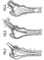
- FIG. 2 shows how the joint prosthesis according to FIG. 1 is inserted after extensive removal of the cancellous bone 12 from a medullary cavity 13 of a cortex 14.
- UV light or ultrasound emitter 5 has already passed halfway through the medullary cavity 13 and has caused part of the prepreg strips 2 to be cured by its radiation penetrating the parts 3 and 4. In contrast to the use of bone cement, there is no heat. Curing takes approximately 6 to 8 minutes using ultraviolet light to cure.
- the aids that are no longer required that is to say parts 3 to 10 are removed, for which purpose a channel (15 in FIG. 4) is provided in adapter part 1 with respect to parts 3 to 7. It is surrounded by the threaded neck 1b (Fig. 1), onto which the mounting aid 10 can be screwed for accomplishing the processes of pressing the prepreg part 2 and curing.
- the assembly aid 10 is unscrewed and after removing the rest Instead, an articulated head 16, for example an aluminum oxide ceramic ball, is screwed on, as shown in FIG. 4 to show the final state.
- the threaded neck 1 b has a self-locking, conical thread for this purpose.
- the prosthesis according to the invention can be repaired by replacing individual parts.
- a new prosthesis can later be easily inserted due to the available cavity, which can be of a conventional type or can also correspond to the embodiment according to the invention.
Abstract
Description
Die Erfindung betrifft eine in der orthopädischen Chirurgie häufig angewendete Endoprothese (Gelenkprothese). Sie ist für alle Arten von Endoprothesen anwendbar, obgleich sich die nachfolgende Beschreibung eines Ausführungsbeipiels ausschliesslich auf eine Hüftgelenkprothese bezieht.The invention relates to an endoprosthesis (joint prosthesis) frequently used in orthopedic surgery. It can be used for all types of endoprostheses, although the following description of an exemplary embodiment relates exclusively to a hip joint prosthesis.
Die verschiedensten Indikationen können es angebracht erscheinen lassen, einem Patienten einen Gelenkersatz zu implantieren. Die herkömmlichen Endoprothesen haben aber nur eine Lebensdauer von etwa fünf bis acht Jahren. Die häufigste Versagensform dieser Prothesen ist die Lockerung aus dem Zementköcher bzw. bei zementlos eingesetzten Prothesen aus der Kortikalis des Femur. Die herkömmliche zementlos eingesetzte Endoprothese hat den Nachteil, dass der in den Knochen (z.B. Femur) hineinragende Schaft durch die notwendige Konfektionierung in einer bestimmten Anzahl von Grössen und durch das Fehlen einer weiteren Krümmung aus der einzigen Krümmungsebene heraus (keine Unterscheidung von rechts und links) ungenügend an die Form des Markhohlraums angepasst ist. Die daraus resultierenden punktuellen Auflagen führen zu örtlich sehr hohen Querbelastungen sowie Entlastungen der Kortikalis in Längsrichtung und damit zu Resorptionen im oberen Bereich des Prothesenansatzes. Die zementierte Endoprothese ist zwar durch den Zement formschlüssig in dem Hohlraum verankert, jedoch stellt der Verbund zwischen Prothesenschaft und Zementköcher ein um etwa eine Zehnerpotenz biegesteiferes Bauteil dar als die Kortikalisröhre des Knochens. Die Folge ist eine Umorientierung des Kraftflusses in der Kortikalis mit einer grossflächigen Entlastung sowie örtlichen Überbelastungen quer zur Faserorientierung.Various indications can make it seem appropriate to implant a joint replacement in a patient. However, conventional endoprostheses only have a lifespan of around five to eight years. The most common form of failure of these prostheses is loosening from the cement tube or, in the case of cementless prostheses, from the cortex of the femur. The conventional cementless endoprosthesis has the disadvantage that the stem protruding into the bone (e.g. femur) due to the necessary assembly in a certain number of sizes and due to the lack of a further curvature out of the single plane of curvature (no distinction between right and left) is insufficiently adapted to the shape of the medullary cavity. The resulting punctiform supports lead to locally very high transverse loads as well as relief of the cortex in the longitudinal direction and thus to resorption in the upper area of the prosthesis attachment. The cemented endoprosthesis is anchored in the cavity in a form-fitting manner by the cement, but the bond between the prosthesis socket and the cement holder represents a component that is more rigid than the cortex tube of the bone by about a power of ten. The result is a reorientation of the flow of force in the cortex with a large relief and local overloads across the fiber orientation.
Dementsprechend liegt der Erfindung die Aufgabe zugrunde, eine Gelenkprothese zu schaffen, die in Form und Steifigkeitsverteilung ohne wesentliche Kompromisse an die Kortikalis des Knochens individuell angepasst werden kann und in der Lage ist, die für den allgemeinen Bewegungsablauf erforderlichen Kräfte sowohl statisch als auch dynamisch zu ertragen und auf physiologische Weise in die Kortikalis einzuleiten, so dass Lockerungen in geringerem Masse zu erwarten sind als bei herkömmlichen Prothesen.Accordingly, the invention has for its object to provide a joint prosthesis that can be individually adapted in shape and stiffness distribution without significant compromises to the cortex of the bone and is able to endure the forces required for the general course of movement both statically and dynamically and introduced into the cortex in a physiological manner, so that loosening is to be expected to a lesser extent than with conventional prostheses.
Diese Aufgabe wird gelöst durch die Gelenkprothese mit den Merkmalen des Patentanspruches 1. Vorteilhafte Weiterbildungen sind in den Unteransprüchen angegeben. Der dabei verwendete Begriff «Prepreg» ist die übliche Bezeichnung für bereits mit einem Matrix-Kunststoff benetzte Faser-Gelege (Glas, Kohle, Aramid od. ähnliches), die noch nicht ausgehärtet sind, d.h. deren Polymerisationsprozess erst durch äussere Einflüsse wie Wärme, ultraviolettes Licht, Licht, Ultraschall oder ähnliches angeregt werden muss. Der dabei verwendete Matrix-Kunststoff ist ein Kunststoff, der in flüssiger Form mit Fasern oder Geweben in Verbindung gebracht wird und nach der Aushärtung einen Verbund zwischen den einzelnen Fibern bzw. Fasern herstellt. Diese sind in dem Gelege aufeinandergeschichtet oder in Gestalt gerichteter Gewebe mit dem Ziel enthalten, genau definierte, gerichtete Steifigkeiten sowie Festigkeiten des in Verbindung mit geeigneten Matrix-Kunststoffen sich ergebenden Verbundes zu erzeugen.This object is achieved by the joint prosthesis with the features of claim 1. Advantageous further developments are specified in the subclaims. The term "prepreg" used here is the usual name for fiber fabrics (glass, carbon, aramid or the like) which have already been wetted with a matrix plastic and which have not yet hardened, i.e. whose polymerization process first has to be stimulated by external influences such as heat, ultraviolet light, light, ultrasound or the like. The matrix plastic used is a plastic that is connected in liquid form to fibers or fabrics and, after curing, creates a bond between the individual fibers or fibers. These are stacked on top of one another in the scrim or contained in the form of directed fabric with the aim of producing precisely defined, directed stiffnesses and strengths of the composite resulting in connection with suitable matrix plastics.
Bevorzugt besteht das Prepreg-Teil aus besonders zugeschnittenen endseitig befestigten Streifen, welche die tragende und krafteinleitende Funktion der Prothese übernehmen und erst während der Operationsphase durch die Verwendung von ultraviolettem Licht oder Ultraschall ausgehärtet werden und damit exakt an die Kortikalis angepasst werden. Die Kraftüberleitung auf einen Gelenkkopf, beispielsweise eine Aluminiumoxid-Keramikkugel geschieht durch ein besonders geformtes Anpassteil (Adapter), das bevorzugt aus einer körperveträglichen Titanlegierung besteht. Durch die Anwendung eines bereits in der Zahnmedizin gebräuchlichen Kunststoffs, der durch ultraviolettes Licht aushärtet, zum Einbetten der Fasern der Prepreg-Streifen entstehen keine zusätzlichen Komplikationen im Zusammenhang mit der Körperverträglichkeit des gesamten Implantats. Vielmehr ist gleiche oder bessere Verträglichkeit mit dem menschlichen Körper zu erwarten als bei herkömmlichen Prothesen. Allefür die Implantation notwendigen Hilfsstoffe und Vorrichtungen können aus gebräuchlichen sterilisierbaren Stoffen gefertigt werden. Als Faserwerkstoff wird Glas, Aramid oder bei Aushärtung durch Ultraschall auch Carbon verwendet.The prepreg part preferably consists of specially cut strips fastened at the end, which take over the load-bearing and force-introducing function of the prosthesis and are hardened only during the operation phase by using ultraviolet light or ultrasound and are therefore precisely adapted to the cortex. The transfer of force to a joint head, for example an aluminum oxide ceramic ball, takes place through a specially shaped adapter (adapter), which preferably consists of a body-compatible titanium alloy. By using a plastic that is already used in dentistry and hardens by ultraviolet light to embed the fibers of the prepreg strips, there are no additional complications in connection with the body tolerance of the entire implant. Rather, the same or better compatibility with the human body can be expected than with conventional prostheses. All the auxiliary materials and devices required for implantation can be made from customary sterilizable materials. Glass, aramid or, if hardened by ultrasound, carbon are used as the fiber material.
Die grössere Lebensdauer durch verminderte Gefahr der Lockerung und der damit verbundenen Bruchgefahr bei herkömmlichen Prothesen verdankt die erfindungsgemässe Gelenkprothese der besseren individuellen Anpassbarkeit der tragenden und krafteinleitenden Struktur des Implantats (Prepreg-Teil) an die physiologischen Gegebenheiten (Form, Rauhigkeit) des Markhohlraums während des Einsetzens der Gelenkprothese im Verlauf einer Operation sowie der an die physiologischen Bedingungen (Biegesteifigkeit) besser angepassten Krafteinleitung in die Kortikalis des Knochens bei weitgehender Vermeidung von unphysiologischen Kräften senkrecht zur Faserorientierung der Kortikalis. Dabei ist die neue Gelenkprothese ohne wesentlich grösseren Aufwand zu implantieren als die herkömmlichen Prothesen, und sie ist im Falle einer eventuellen notwendigen Reoperation ohne grossen Aufwand zu entfernen. Sie ist in allen Fällen einsetzbar, in denen derzeit die konventionelle Form der Prothese benutzt wird, und im besonderen, wenn eine physiologische Abnormität die Einpassung einer konventionellen Prothese erschwert oder unmöglich macht, weil diese nur in bestimmten Abmessungen konfektioniert auf dem Markt angeboten wird. Durch hohe Anpassungsfähigkeit ist das Anwendungsspektrum bedeutend weiter als das der herkömmlichen Prothesenform.The longer life due to the reduced risk of loosening and the associated risk of breakage in conventional prostheses is due to the joint prosthesis according to the invention of the better individual adaptability of the load-bearing and force-introducing structure of the implant (prepreg part) to the physiological conditions (shape, roughness) of the medullary cavity during insertion the joint prosthesis in the course of an operation and the introduction of force into the cortex of the bone, which is better adapted to the physiological conditions (flexural rigidity) while largely avoiding unphysiological forces perpendicular to the fiber orientation of the cortex. The new joint prosthesis can be implanted without much greater effort than the conventional prosthesis, and it can be removed without great effort in the event of a necessary reoperation. It can be used in all cases in which the conventional form of the prosthesis is currently being used, and in particular when a physiological abnormality makes it difficult or impossible to fit a conventional prosthesis because it is only available in certain dimensions on the market, ready-made. Due to its high adaptability, the range of applications is significantly wider than that of the conventional prosthesis shape.
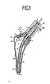
Anhand der Zeichnungen wird ein bevorzugtes Ausführungsbeispiel der Erfindung beschrieben, bei welchem das Prepreg-Teil und eine Anpressmittel durch voneinander getrennte Teile gebildet sind, während die Einführhilfe und das Einführungsteil für das Aushärtemittel durch ein gemeinsames, beide Funktionen erfüllendes Teil gebildet sind, das hohl ist und durchlässig, sowohl für ein Strömungsmittel zum Aufblähen der Anpressmittel als auch für Strahlung von einem zum Aushärten des Prepreg-Teiles vorgesehenen Strahler, der in dem hohlen Teil, das zugleich Einführhilfe und Einführungsteil ist, geführt ist. Es ist ersichtlich, dass die Art der Zuordnung verschiedener Funktionen zu unterschiedlichen bzw. gemeinsamen Teilen, wie es im folgenden beschrieben und dargestellt ist, nur eine der möglichen Ausführungsformen wiedergibt. Es zeigen:
- Fig. 1 im Längsschnitt dargestellt eine Gelenkprothese als Ausführungsbeispiel der Erfindung,
- Fig. 2 die Hauptbestandteile derselben Gelenkprothese, die in eine Kortikalis eingesetzt, dort aber noch nicht befestigt ist,
- Fig. 3 die Anordnung nach Fig. 2, jedoch während des Aushärtens, und
- Fig. 4 die fertig eingesetzte und vervollständigte Gelenkprothese.
- 1 shows in longitudinal section a joint prosthesis as an embodiment of the invention,
- 2 shows the main components of the same joint prosthesis, which is inserted into a cortex but is not yet attached there,
- Fig. 3 shows the arrangement of FIG. 2, but during curing, and
- Fig. 4 shows the fully inserted and completed joint prosthesis.
In den untereinander mit identischen Bezugszeichen versehenen Figuren ist übereinstimmend die folgende Anordnung vorhanden:
- Ein zweiteiliges Anpassteil 1, welches eine Klemmverbindung mit einem Prepreg-
Teil 2 bildet, ist mit einem Halteteil 1 versehen, auf dessenGewindehals 1 b ein Überwurfteil 1 c aufgeschraubt ist. Das Prepreg-Teil 2 ist mit seinem oberen Bereich zwischen den Teilen 1 a und 1 c eingespannt. Eine durch den Gewindehals des Anpassteils 1 hindurchgeführte, in das Prepreg-Teil hineinragende, Einführhilfe 3 stellt zugleich das sogenannte Einführungsteil dar, auf das verschiedentlich getrennt Bezug genommen wird. Anpressmittel 4 sind im Inneren des Prepreg-Teils in Gestalt eines Folienbeutels und eines am unteren Ende des Einführungsteiles 3 zusammen mit diesem verschlossenen, aufblähbaren Schlauches vorgesehen. Ein in das Einführungsteil hineinführbarer UV-Licht- oder Ultraschall-Strahler 5 ist mitTransportmitteln 6 versehen. Weiterhin sind ein Rohr 7,Dichtungen 8 und 9 und eineMontagehilfe 10 mit einemStutzen 10a vorgesehen. DieMontagehilfe 10 besteht aus einem aufschraubbaren Adapter, welcher die notwendigen Anschlüsse zum Durchlass von Strömungs- und Aushärtemitteln aufweist. Durch die Montagehilfe ist wegen der vergrösserten zugänglichen Oberfläche die Handhabung der Prothese bei der Implantation erleichtert.
- A two-part adapter 1, which forms a clamp connection with a
prepreg part 2, is provided with a holding part 1, on the threadedneck 1 b, a coupling part 1 c is screwed. Theprepreg part 2 is clamped with its upper region between parts 1 a and 1 c. An insertion aid 3, which extends through the threaded neck of the adapter 1 and projects into the prepreg part, also represents the so-called insertion part, to which reference is made separately in various ways. Pressing means 4 are provided in the interior of the prepreg part in the form of a foil bag and at the lower end of the insertion part 3 together with this inflatable tube which is closed. A UV light or ultrasound emitter 5 that can be inserted into the insertion part is provided withtransport means 6. Furthermore, a tube 7,seals 8 and 9 and anassembly aid 10 with anozzle 10a are provided. Theassembly aid 10 consists of a screw-on adapter, which has the necessary connections for the passage of flow and curing agents. The assembly aid makes handling the prosthesis easier during implantation due to the larger accessible surface.
Das Prepreg-Teil 2 besteht aus Längsstreifen und/oder gegenläufigen spiraligen Streifen, die auf geeignete Weise verwoben sind, die zwischen dem Halteteil 1 a und dem aufgeschraubten Überwurfteil 1 c eingeklemmt sind und auf diese Weise den Eindruck einer gefiederten Glocke erwecken, die jedoch - falls die Aushärtung nicht auch hier erst in der Operationsphase erfolgt - in einem oberen Bereich, wo sie am Anpassteil 1 befestigt ist, ausgehärtet ist, während sie in einem unteren Bereich 2b noch verformbar und unausgehärtet vorliegt.The
In dem Gewindehals 1 b steckt ein Rohr 7, in welches wiederum die Einführhilfe 3 so eingesteckt ist, dass das weitgehend für Strömungsmittel undurchlässige, insbesondere luftdichte und aufblähbare Anpressmittel 4 an dessen oberen, dem Anpassteil 1 zugewandten Ende eingeklemmt ist. Zur Aufblähung dieses Anpressmittels 4, z.B. Folien- oder Gummisackes, kann durch den Stutzen 1 Oa Luft durch die Montagehilfe 10, das Rohr 7, die Einführhilfe 3 und darin vorgesehene Löcher 3a in die Anpressmittel 4 geleitet werden. Um das Entweichen dieser Luft an unerwünschten Stellen zu verhindern, sind die Dichtungen 8 und 9 vorgesehen. Zum Gewährleisten des Entweichens der Luft aus dem Hohlraum 11 ist eine nicht näher dargestellte Entlüftung in dem Anpassteil 1 vorgesehen, durch welche auch Luft (zusätzlich oder anstelle der 'Druckluftanwendung über den Stutzen 10a) abgesaugt werden kann. Die in die Anpressmittel 4 gedrückte und/oder aus dem Hohlraum 11 gesaugte Luft ist das im vorliegenden Ausführungsbeispiel anzuwendende Strömungsmittel, durch welches die Anpressmittel 4 aufblähbar sind, um die Streifen des Prepreg-Teiles 2 im Bereich 2b gegen die Knocheninnenwand zu pressen. Um diesen angepassten Zustand zu konservieren, ist ein Aushärtemittel vorgesehen, nämlich der Strahler 5.In the threaded
Zum Einführen ist das Einführungsteil 3 in Gestalt eines Rohres aus Polyäthylen oder ähnlichem vorgesehen, das zugleich als Einführhilfe für die noch flexiblen Teile 2 (im Bereich 2b) und 4 dient.For insertion, the insertion part 3 is provided in the form of a tube made of polyethylene or the like, which also serves as an insertion aid for the still flexible parts 2 (in the
Als Transportmittel 6 für den Strahler 5 dient ein längliches, federnd nachgiebiges Element, mittels dessen dem Strahler Energie zugeführt wird, entweder in Gestalt elektrischer Energie oder von ultraviolettem Licht, wenn das Transportmittel 6 zugleich als Lichtleiter ausgebildet ist. Der Transport des Strahlers 5 erfolgt mit definierter Ausziehgeschwindigkeit durch nicht dargestellte Antriebsmittel, die an der Montagehilfe 10 befestigt sein können. Die Prepreg-Streifen im Bereich 2b können so ausgebildet sein, dass dazwischen Leerräume verbleiben, wenn sie an eine Knocheninnenwand angedrückt sind. In diese Zwischenräume kann dann später Knochengewebe einwachsen. Als Kunststoffmaterial der Prepregs kann z.B. ein Material verwendet werden, welches unter der Bezeichnung «UVIOBOND»° in der zahnärztlichen Praxis Verwendung findet.An elongated, resilient element, by means of which energy is supplied to the radiator, either in the form of electrical energy or of ultraviolet light, is used as the transport means 6 for the radiator 5, if the transport means 6 is also designed as a light guide. The emitter 5 is transported at a defined pull-out speed by drive means, not shown, which can be attached to the
In Fig. 2 ist gezeigt, wie die Gelenkprothese nach Fig. 1 nach weitgehendem Ausräumen des Spongiosa 12 aus einem Markhohlraum 13 einer Kortikalis 14 eingesetzt ist.FIG. 2 shows how the joint prosthesis according to FIG. 1 is inserted after extensive removal of the
Fig. 3 zeigt eine spätere Phase mit angepressten Prepreg-Streifen nach dem Eindrücken von Luft in den Stutzen 10a unter leichtem Überdruck von ungefähr 0,8 bar. Der UV-Licht- oder Ultraschall-Strahler 5 hat den Markhohlraum 13 schon zur Hälfte durchlaufen und durch seine die Teile 3 und 4 durchdringende Strahlung die Aushärtung eines Teils der Prepreg-Streifen 2 bewirkt. Dabei entsteht keine Wärme im Gegensatz zur Verwendung von Knochenzement. Die Aushärtung dauert ungefähr 6 bis 8 Minuten bei Verwendung von ultraviolettem Licht zur Aushärtung.3 shows a later phase with pressed prepreg strips after air has been pressed into the
Nach Beendigung der in Fig. 3 gezeigten Phase werden die nicht mehr benötigten Hilfsmittel, also die Teile 3 bis 10 entfernt, wofür bezüglich der Teile 3 bis 7 ein Kanal (15 in Fig. 4) im Anpassteil 1 vorgesehen ist. Er ist von dem Gewindehals 1 b (Fig. 1) umgeben, auf welchen die Montagehilfe 10 aufschraubbaristfürdie Bewerkstelligung der Vorgänge des Anpressens des Prepreg-Teiles 2 und der Aushärtung. Nach dem Aushärten wird die Montagehilfe 10 abgeschraubt und nach dem Entfernen der restlichen Hilfsmittel statt dessen ein Gelenkkopf 16, z.B. eine Aluminiumoxid-Keramikkugel aufgeschraubt, wie es in Fig. 4 zur Darstellung des Endzustandes gezeigt ist. Der Gewindehals 1 b weist zu diesem Zweck ein selbsthemmendes, konisches Gewinde auf.After the phase shown in FIG. 3 has ended, the aids that are no longer required, that is to say parts 3 to 10, are removed, for which purpose a channel (15 in FIG. 4) is provided in adapter part 1 with respect to parts 3 to 7. It is surrounded by the threaded
Der weitere Verlauf der Operation, einschliesslich des Einsetzens der Hüftpfanne, geschieht in der herkömmlichen Art und Weise.The rest of the operation, including the insertion of the acetabulum, is done in the conventional way.
Während bei den bekannten Hüftgelenkprothesen die Krafteinleitung in den Knochen unter Ausbildung von Querkräften geschieht, denen der Knochen in der Regel nicht gewachsen ist, erfolgt die Krafteinleitung bei der Gelenkprothese nach der Erfindung in der physiologisch richtigen Richtung, wobei die Prothese einerseits ein grosses Trägheitsmoment aufweist und andererseits die Einleitungskräfte pro Flächeneinheit wegen der grossen beteiligten Flächen gering sind. Querbelastungen des Knochens und eine mehr oder weniger punktförmige Kraftübertragung wie bei herkömmlichen Prothesen werden vermieden, zumal die Struktur selbst elastisch ist und damit den elastischen Verformungen des Knochens folgen kann.While in the known hip joint prostheses the force is introduced into the bones with the formation of transverse forces which the bone is generally not able to withstand, the force is applied in the joint prosthesis according to the invention in the physiologically correct direction, the prosthesis on the one hand having a large moment of inertia and on the other hand, the initial forces per unit area are low due to the large areas involved. Cross loads on the bone and more or less point-like power transmission as with conventional prostheses are avoided, especially since the structure itself is elastic and can therefore follow the elastic deformations of the bone.
Eine Reparatur der erfindungsgemässen Prothese ist im Gegensatz zu den bekannten Prothesen durch Ersatz einzelner Teile möglich. Darüber hinaus kann später eine neue Prothese wegen des zur Verfügung stehenden Hohlraumes ohne weiteres eingebracht werden, wobei diese herkömmlicher Art sein oder auch der erfindungsgemässen Ausführungsform entsprechen kann.In contrast to the known prostheses, the prosthesis according to the invention can be repaired by replacing individual parts. In addition, a new prosthesis can later be easily inserted due to the available cavity, which can be of a conventional type or can also correspond to the embodiment according to the invention.
Claims (15)
Priority Applications (1)
| Application Number | Priority Date | Filing Date | Title |
|---|---|---|---|
| AT82900937T ATE15324T1 (en) | 1981-04-01 | 1982-04-01 | JOINT PROSTHESIS. |
Applications Claiming Priority (4)
| Application Number | Priority Date | Filing Date | Title |
|---|---|---|---|
| DE3113531 | 1981-04-01 | ||
| DE3113531 | 1981-04-01 | ||
| DE3142730 | 1981-10-23 | ||
| DE19813142730 DE3142730A1 (en) | 1981-04-01 | 1981-10-23 | "JOINT PROSTHESIS" |
Publications (2)
| Publication Number | Publication Date |
|---|---|
| EP0074981A1 EP0074981A1 (en) | 1983-03-30 |
| EP0074981B1 true EP0074981B1 (en) | 1985-09-04 |
Family
ID=25792437
Family Applications (2)
| Application Number | Title | Priority Date | Filing Date |
|---|---|---|---|
| EP82730043A Pending EP0061993A1 (en) | 1981-04-01 | 1982-04-01 | Joint prosthesis |
| EP82900937A Expired EP0074981B1 (en) | 1981-04-01 | 1982-04-01 | Joint prosthesis |
Family Applications Before (1)
| Application Number | Title | Priority Date | Filing Date |
|---|---|---|---|
| EP82730043A Pending EP0061993A1 (en) | 1981-04-01 | 1982-04-01 | Joint prosthesis |
Country Status (4)
| Country | Link |
|---|---|
| US (1) | US4562598A (en) |
| EP (2) | EP0061993A1 (en) |
| DE (2) | DE3142730A1 (en) |
| WO (1) | WO1982003323A1 (en) |
Cited By (1)
| Publication number | Priority date | Publication date | Assignee | Title |
|---|---|---|---|---|
| DE3924990A1 (en) * | 1989-06-13 | 1991-02-14 | Man Technologie Gmbh | Hip joint prosthesis shank |
Families Citing this family (160)
| Publication number | Priority date | Publication date | Assignee | Title |
|---|---|---|---|---|
| NL8302178A (en) * | 1983-06-17 | 1985-01-16 | Stewal N V | METHOD AND TOOLS FOR MAKING A PROSTHESIS |
| IL70736A (en) * | 1984-01-20 | 1988-05-31 | Rosenberg Lior | Self-locking pin device particularly useful for internally fixing bone fractures |
| GB8501907D0 (en) * | 1985-01-25 | 1985-02-27 | Thackray C F Ltd | Surgical instruments |
| CH665554A5 (en) * | 1985-02-07 | 1988-05-31 | Sulzer Ag | BONE IMPLANT. |
| FR2580170B1 (en) * | 1985-04-12 | 1987-11-27 | Meta Ceram | FEMALE HEAD FOR HIP PROSTHESIS |
| US4888024A (en) * | 1985-11-08 | 1989-12-19 | Powlan Roy Y | Prosthetic device and method of fixation within the medullary cavity of bones |
| US4892550A (en) * | 1985-12-30 | 1990-01-09 | Huebsch Donald L | Endoprosthesis device and method |
| US4888022A (en) * | 1985-12-30 | 1989-12-19 | Huebsch Donald L | Endoprosthesis |
| US4714478A (en) * | 1986-01-17 | 1987-12-22 | Fischer William B | Prosthesis, method, and tool for installing same |
| WO1988006023A1 (en) * | 1987-02-20 | 1988-08-25 | Klaus Draenert | Suction drainage-bone screw |
| FR2616060B1 (en) * | 1987-06-03 | 1996-07-12 | Tornier Sa | HIP PROSTHESIS WITH VARIABLE EPIPHYSIS |
| FR2629337A1 (en) * | 1988-03-30 | 1989-10-06 | Bigan Michel | Device for intra-osseus sealing of a prosthesis element |
| CH674928A5 (en) * | 1988-07-05 | 1990-08-15 | Experimentelle Chirurgie Lab | |
| CH676196A5 (en) * | 1988-08-30 | 1990-12-28 | Sulzer Ag | |
| DE3902775A1 (en) * | 1989-01-31 | 1990-08-02 | Labitzke Reiner Prof Dr Med Ha | Femoral joint prosthesis |
| US4969888A (en) * | 1989-02-09 | 1990-11-13 | Arie Scholten | Surgical protocol for fixation of osteoporotic bone using inflatable device |
| DE3914163C1 (en) * | 1989-04-28 | 1990-08-30 | Aesculap Ag, 7200 Tuttlingen, De | |
| EP0412588B1 (en) * | 1989-06-30 | 1998-10-07 | Ligustica S.A. | Epoxy prepreg |
| CH680564A5 (en) * | 1989-12-07 | 1992-09-30 | Experimentelle Chirurgie Schwe | |
| US5171244A (en) * | 1990-01-08 | 1992-12-15 | Caspari Richard B | Methods and apparatus for arthroscopic prosthetic knee replacement |
| US5147366A (en) * | 1990-03-01 | 1992-09-15 | Pfizer Hospital Products Group, Inc. | Pressurization of bone cement surrounding an endoprosthesis |
| US5092891A (en) * | 1990-03-08 | 1992-03-03 | Kummer Frederick J | Cement plug for the medullary canal of a bone and coacting tool for installing same |
| US6990982B1 (en) | 1990-06-28 | 2006-01-31 | Bonutti Ip, Llc | Method for harvesting and processing cells from tissue fragments |
| US5269785A (en) | 1990-06-28 | 1993-12-14 | Bonutti Peter M | Apparatus and method for tissue removal |
| CS277533B6 (en) * | 1990-12-29 | 1993-03-17 | Krajicek Milan | Fixed osteaosynthesis appliance |
| US6280675B1 (en) * | 1991-04-30 | 2001-08-28 | Proseal | Grouting method for rigidly connecting two elements using a binder, and in particular for anchoring one element in another |
| US5329846A (en) | 1991-08-12 | 1994-07-19 | Bonutti Peter M | Tissue press and system |
| US6503277B2 (en) | 1991-08-12 | 2003-01-07 | Peter M. Bonutti | Method of transplanting human body tissue |
| DE59309853D1 (en) * | 1992-06-15 | 1999-12-02 | Klaus Draenert | MEMBRANE SEAL FOR SEALING BONE OPENINGS |
| ES2135520T3 (en) * | 1993-11-04 | 1999-11-01 | Bard Inc C R | NON-MIGRANT VASCULAR PROSTHESIS. |
| US6248110B1 (en) * | 1994-01-26 | 2001-06-19 | Kyphon, Inc. | Systems and methods for treating fractured or diseased bone using expandable bodies |
| US20030229372A1 (en) * | 1994-01-26 | 2003-12-11 | Kyphon Inc. | Inflatable device for use in surgical protocols relating to treatment of fractured or diseased bone |
| JP3333211B2 (en) * | 1994-01-26 | 2002-10-15 | レイリー,マーク・エイ | Improved expandable device for use in a surgical method for bone treatment |
| US20060100635A1 (en) * | 1994-01-26 | 2006-05-11 | Kyphon, Inc. | Inflatable device for use in surgical protocol relating to fixation of bone |
| US6241734B1 (en) * | 1998-08-14 | 2001-06-05 | Kyphon, Inc. | Systems and methods for placing materials into bone |
| DE69534156T2 (en) | 1994-01-26 | 2005-09-29 | Kyphon Inc., Sunnyvale | Improved inflatable device for use in surgical protocols relating to bone fixation |
| DE69406950T2 (en) * | 1994-01-27 | 1998-06-18 | Gore & Ass | DEVICE FOR PROTECTING JOINT PROSTHESES AGAINST WEAR RESIDUES |
| US6132470A (en) * | 1994-01-27 | 2000-10-17 | W. L. Gore & Associates, Inc. | Apparatus and method for protecting prosthetic joint assembly from wear |
| DE4424883A1 (en) * | 1994-07-14 | 1996-01-18 | Merck Patent Gmbh | Femoral prosthesis |
| US20050131269A1 (en) * | 1995-06-07 | 2005-06-16 | Talmadge Karen D. | System and method for delivering a therapeutic agent for bone disease |
| US20050131267A1 (en) * | 1995-06-07 | 2005-06-16 | Talmadge Karen D. | System and method for delivering a therapeutic agent for bone disease |
| US5718717A (en) | 1996-08-19 | 1998-02-17 | Bonutti; Peter M. | Suture anchor |
| US20070282443A1 (en) * | 1997-03-07 | 2007-12-06 | Disc-O-Tech Medical Technologies Ltd. | Expandable element |
| IL128261A0 (en) * | 1999-01-27 | 1999-11-30 | Disc O Tech Medical Tech Ltd | Expandable element |
| US6475230B1 (en) * | 1997-08-01 | 2002-11-05 | Peter M. Bonutti | Method and apparatus for securing a suture |
| DE19740690A1 (en) * | 1997-09-16 | 1999-03-18 | Copf Franz Prof Dr Med | Cortical layer upper thigh bone prothesis |
| US6045551A (en) | 1998-02-06 | 2000-04-04 | Bonutti; Peter M. | Bone suture |
| US7621950B1 (en) | 1999-01-27 | 2009-11-24 | Kyphon Sarl | Expandable intervertebral spacer |
| US6447516B1 (en) | 1999-08-09 | 2002-09-10 | Peter M. Bonutti | Method of securing tissue |
| US6368343B1 (en) | 2000-03-13 | 2002-04-09 | Peter M. Bonutti | Method of using ultrasonic vibration to secure body tissue |
| US6635073B2 (en) | 2000-05-03 | 2003-10-21 | Peter M. Bonutti | Method of securing body tissue |
| ES2262642T3 (en) * | 2000-04-05 | 2006-12-01 | Kyphon Inc. | DEVICE FOR THE TREATMENT OF FRACTURED AND / OR SICK BONES. |
| US6632235B2 (en) * | 2001-04-19 | 2003-10-14 | Synthes (U.S.A.) | Inflatable device and method for reducing fractures in bone and in treating the spine |
| CN1835720B (en) * | 2001-07-25 | 2011-09-28 | Disc整形外科技术股份有限公司 | Deformable tools and implants |
| US6692529B2 (en) * | 2001-09-27 | 2004-02-17 | Mrugesh K. Shah | Hip replacement system having fat lubricant |
| US6719765B2 (en) | 2001-12-03 | 2004-04-13 | Bonutti 2003 Trust-A | Magnetic suturing system and method |
| US20050080425A1 (en) * | 2002-03-18 | 2005-04-14 | Mohit Bhatnagar | Minimally invasive bone manipulation device and method of use |
| AU2003218189A1 (en) * | 2002-03-18 | 2003-10-08 | American Osteomedix, Inc. | Minimally invasive bone manipulation device and method of use |
| US20050090936A1 (en) * | 2003-10-24 | 2005-04-28 | Hitt Dale K. | Two-wire control of sprinkler system |
| WO2004047689A1 (en) * | 2002-11-21 | 2004-06-10 | Sdgi Holdings, Inc. | Systems and techniques for intravertebral spinal stablization with expandable devices |
| US7789885B2 (en) * | 2003-01-15 | 2010-09-07 | Biomet Manufacturing Corp. | Instrumentation for knee resection |
| US7837690B2 (en) * | 2003-01-15 | 2010-11-23 | Biomet Manufacturing Corp. | Method and apparatus for less invasive knee resection |
| US7887542B2 (en) * | 2003-01-15 | 2011-02-15 | Biomet Manufacturing Corp. | Method and apparatus for less invasive knee resection |
| US8551100B2 (en) | 2003-01-15 | 2013-10-08 | Biomet Manufacturing, Llc | Instrumentation for knee resection |
| MXPA05008653A (en) | 2003-02-14 | 2006-04-27 | Depuy Spine Inc | In-situ formed intervertebral fusion device and method. |
| EP2311408B1 (en) * | 2003-03-14 | 2019-02-20 | DePuy Spine, Inc. | Hydraulic device for injection of bone cement in percutaneous vertebroplasty |
| US8066713B2 (en) | 2003-03-31 | 2011-11-29 | Depuy Spine, Inc. | Remotely-activated vertebroplasty injection device |
| US20070032567A1 (en) * | 2003-06-17 | 2007-02-08 | Disc-O-Tech Medical | Bone Cement And Methods Of Use Thereof |
| US8415407B2 (en) | 2004-03-21 | 2013-04-09 | Depuy Spine, Inc. | Methods, materials, and apparatus for treating bone and other tissue |
| US8579908B2 (en) | 2003-09-26 | 2013-11-12 | DePuy Synthes Products, LLC. | Device for delivering viscous material |
| US20050107802A1 (en) * | 2003-11-19 | 2005-05-19 | Vanasse Thomas M. | Canal sizer and associated method |
| US7488324B1 (en) | 2003-12-08 | 2009-02-10 | Biomet Manufacturing Corporation | Femoral guide for implanting a femoral knee prosthesis |
| CN101065080B (en) | 2004-07-30 | 2021-10-29 | 德普伊新特斯产品有限责任公司 | Materials and instruments for treating bone and other tissue |
| US7317331B2 (en) * | 2004-11-08 | 2008-01-08 | Tabula, Inc. | Reconfigurable IC that has sections running at different reconfiguration rates |
| US7695479B1 (en) | 2005-04-12 | 2010-04-13 | Biomet Manufacturing Corp. | Femoral sizer |
| US9381024B2 (en) * | 2005-07-31 | 2016-07-05 | DePuy Synthes Products, Inc. | Marked tools |
| US9918767B2 (en) | 2005-08-01 | 2018-03-20 | DePuy Synthes Products, Inc. | Temperature control system |
| US8591583B2 (en) | 2005-08-16 | 2013-11-26 | Benvenue Medical, Inc. | Devices for treating the spine |
| EP1924227B1 (en) * | 2005-08-16 | 2014-12-17 | Benvenue Medical, Inc. | Spinal tissue distraction devices |
| US8366773B2 (en) | 2005-08-16 | 2013-02-05 | Benvenue Medical, Inc. | Apparatus and method for treating bone |
| US8360629B2 (en) | 2005-11-22 | 2013-01-29 | Depuy Spine, Inc. | Mixing apparatus having central and planetary mixing elements |
| US9907659B2 (en) | 2007-04-17 | 2018-03-06 | Biomet Manufacturing, Llc | Method and apparatus for manufacturing an implant |
| US9173661B2 (en) | 2006-02-27 | 2015-11-03 | Biomet Manufacturing, Llc | Patient specific alignment guide with cutting surface and laser indicator |
| US7780672B2 (en) * | 2006-02-27 | 2010-08-24 | Biomet Manufacturing Corp. | Femoral adjustment device and associated method |
| US9918740B2 (en) | 2006-02-27 | 2018-03-20 | Biomet Manufacturing, Llc | Backup surgical instrument system and method |
| US8591516B2 (en) | 2006-02-27 | 2013-11-26 | Biomet Manufacturing, Llc | Patient-specific orthopedic instruments |
| US8603180B2 (en) | 2006-02-27 | 2013-12-10 | Biomet Manufacturing, Llc | Patient-specific acetabular alignment guides |
| US9339278B2 (en) | 2006-02-27 | 2016-05-17 | Biomet Manufacturing, Llc | Patient-specific acetabular guides and associated instruments |
| US9113971B2 (en) | 2006-02-27 | 2015-08-25 | Biomet Manufacturing, Llc | Femoral acetabular impingement guide |
| US9345548B2 (en) | 2006-02-27 | 2016-05-24 | Biomet Manufacturing, Llc | Patient-specific pre-operative planning |
| US8407067B2 (en) | 2007-04-17 | 2013-03-26 | Biomet Manufacturing Corp. | Method and apparatus for manufacturing an implant |
| US8070752B2 (en) * | 2006-02-27 | 2011-12-06 | Biomet Manufacturing Corp. | Patient specific alignment guide and inter-operative adjustment |
| US9289253B2 (en) | 2006-02-27 | 2016-03-22 | Biomet Manufacturing, Llc | Patient-specific shoulder guide |
| US10278711B2 (en) | 2006-02-27 | 2019-05-07 | Biomet Manufacturing, Llc | Patient-specific femoral guide |
| US20150335438A1 (en) | 2006-02-27 | 2015-11-26 | Biomet Manufacturing, Llc. | Patient-specific augments |
| US7806900B2 (en) | 2006-04-26 | 2010-10-05 | Illuminoss Medical, Inc. | Apparatus and methods for delivery of reinforcing materials to bone |
| US7695520B2 (en) * | 2006-05-31 | 2010-04-13 | Biomet Manufacturing Corp. | Prosthesis and implementation system |
| US9795399B2 (en) | 2006-06-09 | 2017-10-24 | Biomet Manufacturing, Llc | Patient-specific knee alignment guide and associated method |
| EP2032191B1 (en) * | 2006-06-29 | 2015-08-12 | Depuy Spine Inc. | Integrated bone biopsy and therapy apparatus |
| EP2068898A4 (en) * | 2006-09-14 | 2011-07-20 | Depuy Spine Inc | Bone cement and methods of use thereof |
| CA2665995C (en) | 2006-10-19 | 2011-11-29 | Oren Globerman | Fluid delivery system |
| US7879041B2 (en) | 2006-11-10 | 2011-02-01 | Illuminoss Medical, Inc. | Systems and methods for internal bone fixation |
| EP2091445B1 (en) | 2006-11-10 | 2015-03-11 | Illuminoss Medical, Inc. | Systems for internal bone fixation |
| US8105382B2 (en) | 2006-12-07 | 2012-01-31 | Interventional Spine, Inc. | Intervertebral implant |
| US8663328B2 (en) * | 2006-12-21 | 2014-03-04 | Warsaw Orthopedic, Inc. | Methods for positioning a load-bearing component of an orthopedic implant device by inserting a malleable device that hardens in vivo |
| US8758407B2 (en) * | 2006-12-21 | 2014-06-24 | Warsaw Orthopedic, Inc. | Methods for positioning a load-bearing orthopedic implant device in vivo |
| EP2124778B1 (en) | 2007-02-21 | 2019-09-25 | Benvenue Medical, Inc. | Devices for treating the spine |
| US20100274246A1 (en) * | 2007-05-10 | 2010-10-28 | Oren Globerman | Expandable intramedullary nail for small bone fixation |
| US10596032B2 (en) | 2007-05-24 | 2020-03-24 | Johnson & Johnson Surgical Vision, Inc. | System and method for controlling a transverse phacoemulsification system with a footpedal |
| WO2008154762A1 (en) * | 2007-06-18 | 2008-12-24 | Roderic Alexander Frei | Anchoring element for endoprostheses in hollow bones |
| US8900307B2 (en) | 2007-06-26 | 2014-12-02 | DePuy Synthes Products, LLC | Highly lordosed fusion cage |
| AU2008278578B2 (en) * | 2007-07-25 | 2012-08-16 | Depuy Spine, Inc. | Expandable bone filler materials and methods of using same |
| US8265949B2 (en) * | 2007-09-27 | 2012-09-11 | Depuy Products, Inc. | Customized patient surgical plan |
| EP2957237A1 (en) * | 2007-09-30 | 2015-12-23 | DePuy Products, Inc. | Customized patient-specific orthopaedic surgical instrumentation |
| US8357111B2 (en) * | 2007-09-30 | 2013-01-22 | Depuy Products, Inc. | Method and system for designing patient-specific orthopaedic surgical instruments |
| WO2009059090A1 (en) * | 2007-10-31 | 2009-05-07 | Illuminoss Medical, Inc. | Light source |
| US8403968B2 (en) | 2007-12-26 | 2013-03-26 | Illuminoss Medical, Inc. | Apparatus and methods for repairing craniomaxillofacial bones using customized bone plates |
| EP2471493A1 (en) | 2008-01-17 | 2012-07-04 | Synthes GmbH | An expandable intervertebral implant and associated method of manufacturing the same |
| KR20110003475A (en) | 2008-04-05 | 2011-01-12 | 신세스 게엠바하 | Expandable intervertebral implant |
| US20100185202A1 (en) * | 2009-01-16 | 2010-07-22 | Lester Mark B | Customized patient-specific patella resectioning guide |
| US8535327B2 (en) | 2009-03-17 | 2013-09-17 | Benvenue Medical, Inc. | Delivery apparatus for use with implantable medical devices |
| US9526620B2 (en) | 2009-03-30 | 2016-12-27 | DePuy Synthes Products, Inc. | Zero profile spinal fusion cage |
| US8210729B2 (en) | 2009-04-06 | 2012-07-03 | Illuminoss Medical, Inc. | Attachment system for light-conducting fibers |
| BRPI1015207A2 (en) * | 2009-04-07 | 2016-05-03 | Illuminoss Medical Inc | photodynamic bone stabilization systems and methods for treating spine conditions |
| US8512338B2 (en) | 2009-04-07 | 2013-08-20 | Illuminoss Medical, Inc. | Photodynamic bone stabilization systems and methods for reinforcing bone |
| BR112012003783A2 (en) | 2009-08-19 | 2016-04-19 | Illuminoss Medical Inc | devices and methods for bone alignment, stabilization and distraction |
| US20110118740A1 (en) * | 2009-11-10 | 2011-05-19 | Illuminoss Medical, Inc. | Intramedullary Implants Having Variable Fastener Placement |
| US9393129B2 (en) | 2009-12-10 | 2016-07-19 | DePuy Synthes Products, Inc. | Bellows-like expandable interbody fusion cage |
| US8684965B2 (en) | 2010-06-21 | 2014-04-01 | Illuminoss Medical, Inc. | Photodynamic bone stabilization and drug delivery systems |
| US8979860B2 (en) | 2010-06-24 | 2015-03-17 | DePuy Synthes Products. LLC | Enhanced cage insertion device |
| US9592063B2 (en) | 2010-06-24 | 2017-03-14 | DePuy Synthes Products, Inc. | Universal trial for lateral cages |
| TW201215379A (en) | 2010-06-29 | 2012-04-16 | Synthes Gmbh | Distractible intervertebral implant |
| US9402732B2 (en) | 2010-10-11 | 2016-08-02 | DePuy Synthes Products, Inc. | Expandable interspinous process spacer implant |
| US9968376B2 (en) | 2010-11-29 | 2018-05-15 | Biomet Manufacturing, Llc | Patient-specific orthopedic instruments |
| WO2012088432A1 (en) | 2010-12-22 | 2012-06-28 | Illuminoss Medical, Inc. | Systems and methods for treating conditions and diseases of the spine |
| US9241745B2 (en) | 2011-03-07 | 2016-01-26 | Biomet Manufacturing, Llc | Patient-specific femoral version guide |
| WO2012178018A2 (en) | 2011-06-24 | 2012-12-27 | Benvenue Medical, Inc. | Devices and methods for treating bone tissue |
| WO2013013071A1 (en) * | 2011-07-19 | 2013-01-24 | Illuminoss Medical, Inc. | Devices and methods for bone restructure and stabilization |
| EP2734266B1 (en) | 2011-07-19 | 2017-12-20 | Illuminoss Medical, Inc. | Devices for bone restructure and stabilization |
| WO2013059609A1 (en) | 2011-10-19 | 2013-04-25 | Illuminoss Medical, Inc. | Systems and methods for joint stabilization |
| US8939977B2 (en) | 2012-07-10 | 2015-01-27 | Illuminoss Medical, Inc. | Systems and methods for separating bone fixation devices from introducer |
| US9687281B2 (en) | 2012-12-20 | 2017-06-27 | Illuminoss Medical, Inc. | Distal tip for bone fixation devices |
| US9522070B2 (en) | 2013-03-07 | 2016-12-20 | Interventional Spine, Inc. | Intervertebral implant |
| US10085783B2 (en) | 2013-03-14 | 2018-10-02 | Izi Medical Products, Llc | Devices and methods for treating bone tissue |
| DE102013016096A1 (en) | 2013-09-27 | 2015-04-02 | Audi Ag | Motor vehicle configuration by means of communication terminal |
| US9867628B2 (en) * | 2013-11-07 | 2018-01-16 | Zimmer, Inc. | Device for extraction of prosthetic implants |
| US11426290B2 (en) | 2015-03-06 | 2022-08-30 | DePuy Synthes Products, Inc. | Expandable intervertebral implant, system, kit and method |
| CN109688980B (en) | 2016-06-28 | 2022-06-10 | Eit 新兴移植技术股份有限公司 | Expandable and angularly adjustable intervertebral cage with articulation joint |
| EP4233801A3 (en) | 2016-06-28 | 2023-09-06 | Eit Emerging Implant Technologies GmbH | Expandable, angularly adjustable intervertebral cages |
| US10888433B2 (en) | 2016-12-14 | 2021-01-12 | DePuy Synthes Products, Inc. | Intervertebral implant inserter and related methods |
| US10722310B2 (en) | 2017-03-13 | 2020-07-28 | Zimmer Biomet CMF and Thoracic, LLC | Virtual surgery planning system and method |
| US10398563B2 (en) | 2017-05-08 | 2019-09-03 | Medos International Sarl | Expandable cage |
| US11344424B2 (en) | 2017-06-14 | 2022-05-31 | Medos International Sarl | Expandable intervertebral implant and related methods |
| US10940016B2 (en) | 2017-07-05 | 2021-03-09 | Medos International Sarl | Expandable intervertebral fusion cage |
| US11051829B2 (en) | 2018-06-26 | 2021-07-06 | DePuy Synthes Products, Inc. | Customized patient-specific orthopaedic surgical instrument |
| EP3813696A4 (en) | 2018-06-27 | 2022-04-13 | IlluminOss Medical, Inc. | Systems and methods for bone stabilization and fixation |
| US11446156B2 (en) | 2018-10-25 | 2022-09-20 | Medos International Sarl | Expandable intervertebral implant, inserter instrument, and related methods |
| US11426286B2 (en) | 2020-03-06 | 2022-08-30 | Eit Emerging Implant Technologies Gmbh | Expandable intervertebral implant |
| US11850160B2 (en) | 2021-03-26 | 2023-12-26 | Medos International Sarl | Expandable lordotic intervertebral fusion cage |
| US11752009B2 (en) | 2021-04-06 | 2023-09-12 | Medos International Sarl | Expandable intervertebral fusion cage |
Family Cites Families (11)
| Publication number | Priority date | Publication date | Assignee | Title |
|---|---|---|---|---|
| CH389231A (en) * | 1961-11-29 | 1965-03-15 | Container Patent Company Gmbh | Process for the production of blown moldings |
| US3643656A (en) * | 1969-06-16 | 1972-02-22 | Joseph V Young | Inflatable surgical cast |
| US3681787A (en) * | 1971-03-26 | 1972-08-08 | Moxness Products Inc | Implantable breast prosthesis filled with gels of different densities |
| DE2305441A1 (en) * | 1973-02-03 | 1974-08-08 | Rosenthal Stemag Tech Keramik | TENSIONER CONNECTION FOR IMPLANTS |
| DE2310113C2 (en) * | 1973-03-01 | 1974-11-07 | Blietz, Rudolf, Dr.Med.Habil., 2800 Bremen | Knee joint endoprosthesis |
| SE403884B (en) * | 1975-04-22 | 1978-09-11 | Branemark Per Ingvar | FOR PARTY AT NAMES INTENDED PROTEST SPECIALLY INTENDED NOT TO BE IN AN ARTIFICIAL JOINT |
| EP0006415A1 (en) * | 1978-06-29 | 1980-01-09 | Osteo Ag | Device for the application of bone cements |
| ATE2477T1 (en) * | 1979-03-15 | 1983-03-15 | Gebrueder Sulzer Aktiengesellschaft | STOCKING COVER FOR THE ANCHORING SHAFT OF AN ARDOPROSTHESIS. |
| US4274163A (en) * | 1979-07-16 | 1981-06-23 | The Regents Of The University Of California | Prosthetic fixation technique |
| US4357716A (en) * | 1980-07-09 | 1982-11-09 | Brown Byron L | Device and method for cementing a hip prosthesis in a femoral canal |
| US4399814A (en) * | 1981-04-27 | 1983-08-23 | Massachusetts Institute Of Technology | Method and apparatus for pressure-coated bones |
-
1981
- 1981-10-23 DE DE19813142730 patent/DE3142730A1/en not_active Withdrawn
-
1982
- 1982-04-01 EP EP82730043A patent/EP0061993A1/en active Pending
- 1982-04-01 EP EP82900937A patent/EP0074981B1/en not_active Expired
- 1982-04-01 US US06/448,914 patent/US4562598A/en not_active Expired - Fee Related
- 1982-04-01 WO PCT/DE1982/000078 patent/WO1982003323A1/en active IP Right Grant
- 1982-04-01 DE DE8282900937T patent/DE3265973D1/en not_active Expired
Cited By (1)
| Publication number | Priority date | Publication date | Assignee | Title |
|---|---|---|---|---|
| DE3924990A1 (en) * | 1989-06-13 | 1991-02-14 | Man Technologie Gmbh | Hip joint prosthesis shank |
Also Published As
| Publication number | Publication date |
|---|---|
| US4562598A (en) | 1986-01-07 |
| DE3142730A1 (en) | 1982-10-21 |
| EP0074981A1 (en) | 1983-03-30 |
| EP0061993A1 (en) | 1982-10-06 |
| DE3265973D1 (en) | 1985-10-10 |
| WO1982003323A1 (en) | 1982-10-14 |
Similar Documents
| Publication | Publication Date | Title |
|---|---|---|
| EP0074981B1 (en) | Joint prosthesis | |
| EP0692228B1 (en) | Femoral prosthesis | |
| DE60320464T2 (en) | Vertebral distractor | |
| EP0197441B1 (en) | Method of treating bone replacement implants | |
| DE2854334C3 (en) | Thigh-hip joint endoprosthesis | |
| DE2535649A1 (en) | CERAMIC CAP PROSTHESIS | |
| CH637286A5 (en) | ARTIFICIAL JOINT FOR IMPLANTING ON HUMAN BODY. | |
| DE3301415A1 (en) | Endoprosthesis | |
| EP1304984B1 (en) | Surgical element | |
| EP0878176B1 (en) | Femoral neck endoprosthesis for an artificial hip joint | |
| DE2502884A1 (en) | Synthetic bone or joint prosthesis - incorporates zones which are gradually absorbed by the body | |
| DE3336005A1 (en) | Endoprosthesis, especially tumour prosthesis | |
| DE3937786C2 (en) | ||
| EP0921771B1 (en) | Method of testing ceramic cotyloid cavities for hip joint endoprostheses | |
| EP2066265B1 (en) | Hip implant | |
| DE4313201C2 (en) | Prosthetic socket set | |
| DE2832555A1 (en) | Hip joint prosthesis | |
| EP1166724A1 (en) | Joint component of a temporary prosthesis and temporary prosthesis | |
| DE4332230C2 (en) | Endoprosthesis, especially a hip endoprosthesis | |
| DE3536516C2 (en) | ||
| DE102021119574B4 (en) | Fixative for a prosthesis | |
| EP3332747A1 (en) | Hip joint endoprosthesis system | |
| DE4221442A1 (en) | Metal stem for cemented hip joint prosthesis - has cross-section corresp. in its distal portion to femur cavity prepared by basting | |
| GB2104390A (en) | Pressurisation of cement in bones | |
| EP4218636A1 (en) | Cement applicator |
Legal Events
| Date | Code | Title | Description |
|---|---|---|---|
| PUAI | Public reference made under article 153(3) epc to a published international application that has entered the european phase |
Free format text: ORIGINAL CODE: 0009012 |
|
| AK | Designated contracting states |
Designated state(s): AT BE CH DE FR GB IT LI NL SE |
|
| 17P | Request for examination filed |
Effective date: 19830406 |
|
| RBV | Designated contracting states (corrected) |
Designated state(s): AT BE CH DE FR GB IT LI NL SE |
|
| XX | Miscellaneous (additional remarks) |
Free format text: VERBUNDEN MIT 82730043.5/006199 (EUROPAEISCHE ANMELDENUMMER/VEROEFFENTLICHUNGSNUMMER) DURCH ENTSCHEIDUNG VOM 07.06.84. |
|
| GRAA | (expected) grant |
Free format text: ORIGINAL CODE: 0009210 |
|
| AK | Designated contracting states |
Designated state(s): AT BE CH DE FR GB IT LI NL SE |
|
| PG25 | Lapsed in a contracting state [announced via postgrant information from national office to epo] |
Ref country code: NL Effective date: 19850904 Ref country code: IT Free format text: LAPSE BECAUSE OF FAILURE TO SUBMIT A TRANSLATION OF THE DESCRIPTION OR TO PAY THE FEE WITHIN THE PRESCRIBED TIME-LIMIT;WARNING: LAPSES OF ITALIAN PATENTS WITH EFFECTIVE DATE BEFORE 2007 MAY HAVE OCCURRED AT ANY TIME BEFORE 2007. THE CORRECT EFFECTIVE DATE MAY BE DIFFERENT FROM THE ONE RECORDED. Effective date: 19850904 |
|
| REF | Corresponds to: |
Ref document number: 15324 Country of ref document: AT Date of ref document: 19850915 Kind code of ref document: T |
|
| XX | Miscellaneous (additional remarks) |
Free format text: VERBUNDEN MIT 82730043.5/006199 (EUROPAEISCHE ANMELDENUMMER/VEROEFFENTLICHUNGSNUMMER) DURCH ENTSCHEIDUNG VOM 07.06.84. |
|
| PG25 | Lapsed in a contracting state [announced via postgrant information from national office to epo] |
Ref country code: SE Effective date: 19850930 |
|
| REF | Corresponds to: |
Ref document number: 3265973 Country of ref document: DE Date of ref document: 19851010 |
|
| ET | Fr: translation filed | ||
| NLV1 | Nl: lapsed or annulled due to failure to fulfill the requirements of art. 29p and 29m of the patents act | ||
| PGFP | Annual fee paid to national office [announced via postgrant information from national office to epo] |
Ref country code: AT Payment date: 19860409 Year of fee payment: 5 |
|
| PLBE | No opposition filed within time limit |
Free format text: ORIGINAL CODE: 0009261 |
|
| STAA | Information on the status of an ep patent application or granted ep patent |
Free format text: STATUS: NO OPPOSITION FILED WITHIN TIME LIMIT |
|
| 26N | No opposition filed | ||
| PG25 | Lapsed in a contracting state [announced via postgrant information from national office to epo] |
Ref country code: AT Effective date: 19870401 |
|
| BERE | Be: lapsed |
Owner name: MECRON MEDIZINISCHE PRODUKTE G.M.B.H. Effective date: 19870430 |
|
| REG | Reference to a national code |
Ref country code: FR Ref legal event code: ST |
|
| REG | Reference to a national code |
Ref country code: FR Ref legal event code: RC |
|
| REG | Reference to a national code |
Ref country code: FR Ref legal event code: DA |
|
| PG25 | Lapsed in a contracting state [announced via postgrant information from national office to epo] |
Ref country code: BE Effective date: 19890430 |
|
| PGFP | Annual fee paid to national office [announced via postgrant information from national office to epo] |
Ref country code: FR Payment date: 19910419 Year of fee payment: 10 |
|
| PGFP | Annual fee paid to national office [announced via postgrant information from national office to epo] |
Ref country code: GB Payment date: 19910425 Year of fee payment: 10 |
|
| PGFP | Annual fee paid to national office [announced via postgrant information from national office to epo] |
Ref country code: CH Payment date: 19910521 Year of fee payment: 10 |
|
| PG25 | Lapsed in a contracting state [announced via postgrant information from national office to epo] |
Ref country code: GB Effective date: 19920401 |
|
| PG25 | Lapsed in a contracting state [announced via postgrant information from national office to epo] |
Ref country code: LI Effective date: 19920430 Ref country code: CH Effective date: 19920430 |
|
| GBPC | Gb: european patent ceased through non-payment of renewal fee | ||
| PG25 | Lapsed in a contracting state [announced via postgrant information from national office to epo] |
Ref country code: FR Effective date: 19921230 |
|
| REG | Reference to a national code |
Ref country code: CH Ref legal event code: AUV Free format text: DAS OBENGENANNTE PATENT IST, MANGELS BEZAHLUNG DER 11. JAHRESGEBUEHR GELOESCHT WORDEN. Ref country code: CH Ref legal event code: PL |
|
| REG | Reference to a national code |
Ref country code: FR Ref legal event code: ST |
|
| PGFP | Annual fee paid to national office [announced via postgrant information from national office to epo] |
Ref country code: DE Payment date: 20010124 Year of fee payment: 20 |