EP0074876A1 - Dispositif universel de supportage et de bridage d'une pièce - Google Patents
Dispositif universel de supportage et de bridage d'une pièce Download PDFInfo
- Publication number
- EP0074876A1 EP0074876A1 EP82401604A EP82401604A EP0074876A1 EP 0074876 A1 EP0074876 A1 EP 0074876A1 EP 82401604 A EP82401604 A EP 82401604A EP 82401604 A EP82401604 A EP 82401604A EP 0074876 A1 EP0074876 A1 EP 0074876A1
- Authority
- EP
- European Patent Office
- Prior art keywords
- aforementioned
- discs
- disc
- base plate
- unclamping
- Prior art date
- Legal status (The legal status is an assumption and is not a legal conclusion. Google has not performed a legal analysis and makes no representation as to the accuracy of the status listed.)
- Ceased
Links
- 238000003754 machining Methods 0.000 claims description 4
- 238000001804 debridement Methods 0.000 description 2
- 230000006978 adaptation Effects 0.000 description 1
- 230000000694 effects Effects 0.000 description 1
- 238000004519 manufacturing process Methods 0.000 description 1
- 238000000034 method Methods 0.000 description 1
- 230000000284 resting effect Effects 0.000 description 1
- 238000005096 rolling process Methods 0.000 description 1
Images
Classifications
-
- B—PERFORMING OPERATIONS; TRANSPORTING
- B23—MACHINE TOOLS; METAL-WORKING NOT OTHERWISE PROVIDED FOR
- B23Q—DETAILS, COMPONENTS, OR ACCESSORIES FOR MACHINE TOOLS, e.g. ARRANGEMENTS FOR COPYING OR CONTROLLING; MACHINE TOOLS IN GENERAL CHARACTERISED BY THE CONSTRUCTION OF PARTICULAR DETAILS OR COMPONENTS; COMBINATIONS OR ASSOCIATIONS OF METAL-WORKING MACHINES, NOT DIRECTED TO A PARTICULAR RESULT
- B23Q3/00—Devices holding, supporting, or positioning work or tools, of a kind normally removable from the machine
- B23Q3/02—Devices holding, supporting, or positioning work or tools, of a kind normally removable from the machine for mounting on a work-table, tool-slide, or analogous part
- B23Q3/10—Auxiliary devices, e.g. bolsters, extension members
Definitions
- the present invention essentially relates to a universal device for supporting and clamping any part with a view to its machining, for example o
- the invention provides a universal device for temporarily supporting and clamping any part with a view to its machining, for example, and of the type comprising a base plate on which are mounted columns or the like supporting the part as well as means for clamping and unclamping this part, characterized in that said columns are respectively secured to discs preferably fitted and which are relatively mobile in rotation on said base plate so that said columns are capable of covering all the points of any given surface and thus to form a support plane adaptable to any shape of part
- the aforementioned discs are arranged concentrically with inside each other, with the exception of at least one of them which is offset from the others.
- the above-mentioned eccentric disc is provided with at least one column which passes through the common center of rotation of the other discs.
- the above-mentioned eccentric disc rotates in a first disc which does not have a column.
- this first disc are concentrically and successively arranged a second and a third disc respectively carrying at least one column.
- all the aforementioned discs are inserted in a crown or the like externally concentric with the aforementioned third disc and secured to the base plate.
- the cooperating surfaces for fitting the discs and the crown are conical
- each disc has, according to the invention, a radial slot so as to be able to make it extendable and integral with the base plate by means of a conical screw or other similar means inserted in said slot.
- the aforementioned crown is provided with a circular groove in which the above-mentioned clamping and unclamping means are fixed in an adjustable manner around the workpiece.
- Each clamping and unclamping means essentially consists of a set of levers urged by springs to bear on the part supported by the aforementioned columns, one of these levers projecting outwards from the crown to bear. on the underside of a hollowed-out unclamping plate secured to the aforementioned base plate.
- the above-mentioned clamping plate is slidably mounted on uprights provided with springs and integral with the base plate, and this clamping plate is actuable by a gantry or the like provided with movable fingers.
- a support and clamping system essentially comprises an assembly 1 for supporting any workpiece 2 and several identical devices for clamping the workpiece 2, such as the one shown at 3 in Figure 3 '.
- the support assembly 1 is arranged on a base plate or pallet 4 so as to be able to easily transport the assembly 1 from one station to another in order to carry out various machining operations on part 2.
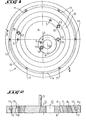
- the support assembly 1 consists of a plurality of discs or rings relatively mobile in rotation on the base plate 4 and bearing, at least for some of them, a column 5 for supporting the part 2.
- Columns 5, as will now be described, are three in number and their relative rotation makes it possible to cover precisely all the points of a any given surface 2a to support.
- the support assembly 1 essentially consists of four nestable discs which are arranged concentrically one inside the other with the exception of one of them which is eccentric relative to the others. More specifically, the assembly 1 is constituted by a first disc 6 which does not carry a column 5, by a second disc 7 which carries a column 5 and by a third disc 8 which also carries a column 5, these three discs 6 , 7 and 8 being concentric and freely movable around a center common 0.
- An eccentric disc or ring 9 is fitted into the first disc 6 and can rotate freely in the latter around the point 0 '.
- This disc 9 which is offset from the others carries a column 5 which, by rotation, passes through the center of rotation 0 of the three concentric discs 6, 7 and 8, as can be seen in FIG. 1 '. This constitutes an essential condition for the three columns 5 associated respectively with the discs 7, 8 and 9, to be able to support any surface, that is to say a part 2 of any shape.
- the discs 6, 7, 8 and 9 are all inserted or fitted into a ring 10 externally concentric with the third disc 8.
- the ring 10 can be fixed to the base plate 4 by means of screws or the like passing through holes shown diagrammatically in 11 in Figures 1 and 2.
- the cooperating surfaces for fitting the disks 6, 7, 8 and 9, and the crown 10 are conical, which allows precise fitting of all these elements while ensuring free relative rotation discs in the crown 10.
- Each disc 6, 7, 8 and 9 has a slot 12 into which any suitable element allowing the extension of the discs can be inserted, this means being for example a conical screw 13.
- the implementation of the support assembly 1 is as follows.
- the columns 5 are first of all adapted to the sides of the surface 2a of the part 2 to be machined.
- the disks are immobilized on the base plate 4, preferably starting with the disk 8 which is the largest.
- the radial extension of the discs as well as their taper allows their application on the pallet 4 with great precision
- the crown 10 has a circular groove 14, for example having a T-shaped profile as can be seen in Figure 2, and which, according to the embodiment shown, allows the introduction and tightening of the screws through the holes or bores 11 for fixing the crown 10 to the base plate 4.
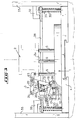
- this T-shaped groove 14 are fixed the devices 3 for clamping and unclamping the part 2, which will now be described with reference to FIG. 3.
- Each device 3 is fixed to the crown 10 by bolts or the like 15 and this by means of an oblong light 16 allowing an appropriate orientation and movement of the device 3 relative to the part 2.
- the device 3 comprises a support 17 having substantially a square shape and on which are articulated in 18 two arms forming levers and namely a first lever 19 and a second lever 10.
- the end 21 of the second lever is articulated at the end of an element d support 22 which includes an oblong opening 23 in which the end of the first lever 19 can be struggled.
- a spring 24 is provided between the two levers 19 and 20, and a another spring 25 is arranged between the support 17 and the first lever 19 as can be seen in FIG. 3.
- the other end of the lever 20 has been shown at 26 which forms an end stop at this point by bearing on support 17
- the first lever 19 has a general shape of a square, a part 19a of which projects outwards from the crown 10 to come below a plate 27 for unclamping.
- This plate 27 has the external dimensions of the pallet 4 and is hollowed out at its center, as shown at 28 in FIG. 3, so as to allow passage over the flanges 3 while covering the projecting elements 19a which carry at their end a roller 29 or other similar rolling means.
- the unclamping plate 27 is slidably mounted along uprights or the like 30 integral with the pallet 4 and provided with springs 31 urging said plate 27 upwards.
- the descent of this plate can be controlled for example by fingers or the like 32 mounted movable along a gantry which was shown very schematically in 33'0
- a universal device has therefore been produced according to the invention for supporting and clamping any part, which has all the qualities of simplicity and reliability required and which finds a particularly advantageous application in flexible workshops.
- the invention is in no way limited to the embodiment described and illustrated, which has been given only by way of example.
- the three movable columns 11 can be of any type and are optionally interchangeable and adjustable in height. It is the same with regard to the possible variants for the clamping system proper 3, as mentioned above.
- the device of the invention comprises more than one disc eccentric with respect to the others, and that the unclamping plate 27 is actuated by means other than the fingers 32 ..
Landscapes
- Engineering & Computer Science (AREA)
- Mechanical Engineering (AREA)
- Jigs For Machine Tools (AREA)
- Machine Tool Units (AREA)
Applications Claiming Priority (2)
| Application Number | Priority Date | Filing Date | Title |
|---|---|---|---|
| FR8117334 | 1981-09-14 | ||
| FR8117334A FR2512721A1 (fr) | 1981-09-14 | 1981-09-14 | Dispositif universel de supportage et de bridage d'une piece |
Publications (1)
| Publication Number | Publication Date |
|---|---|
| EP0074876A1 true EP0074876A1 (fr) | 1983-03-23 |
Family
ID=9262126
Family Applications (1)
| Application Number | Title | Priority Date | Filing Date |
|---|---|---|---|
| EP82401604A Ceased EP0074876A1 (fr) | 1981-09-14 | 1982-08-30 | Dispositif universel de supportage et de bridage d'une pièce |
Country Status (3)
| Country | Link |
|---|---|
| US (1) | US4489926A (enExample) |
| EP (1) | EP0074876A1 (enExample) |
| FR (1) | FR2512721A1 (enExample) |
Cited By (1)
| Publication number | Priority date | Publication date | Assignee | Title |
|---|---|---|---|---|
| CN107825199A (zh) * | 2017-10-31 | 2018-03-23 | 济南大学 | 一种用于两孔轴承座内孔加工的车削夹具及方法 |
Families Citing this family (12)
| Publication number | Priority date | Publication date | Assignee | Title |
|---|---|---|---|---|
| US4543970A (en) * | 1983-02-21 | 1985-10-01 | Tokyo Shibaura Denki Kabushiki Kaisha | Automatic set-up system |
| US4718651A (en) * | 1986-12-30 | 1988-01-12 | Rca Corporation | Self-acting dual-mode clamp |
| US4803828A (en) * | 1987-07-30 | 1989-02-14 | Advanced Micro Devices, Inc. | Fixture for PGA carriers |
| US5092454A (en) * | 1988-11-09 | 1992-03-03 | Acme Manufacturing | Pallet for an integrated buffing and grinding system |
| US5370378A (en) * | 1993-09-13 | 1994-12-06 | Positrol, Inc. | Work holding system |
| US5685413A (en) * | 1995-09-12 | 1997-11-11 | Odawara Automation, Inc. | Adjustable pallet for supporting work pieces |
| US5735219A (en) * | 1996-11-27 | 1998-04-07 | Odawara Automation, Inc. | Open base adjustable pallet for supporting work pieces |
| US7410483B2 (en) * | 2003-05-23 | 2008-08-12 | Novare Surgical Systems, Inc. | Hand-actuated device for remote manipulation of a grasping tool |
| JP5152896B2 (ja) * | 2007-10-10 | 2013-02-27 | 津田駒工業株式会社 | 工作機械における回転割出し装置 |
| CN107297635B (zh) * | 2017-06-28 | 2019-12-27 | 中国航发南方工业有限公司 | 薄壁变形零件的车削夹具及车削固定方法 |
| CN107243622B (zh) * | 2017-08-10 | 2018-06-19 | 安徽理工大学 | 混联式可移动重载铸造机器人 |
| CN108890342B (zh) * | 2018-08-30 | 2023-11-03 | 中山金菱机械有限公司 | 一种新型的数字化立式车床加工环形件的夹具 |
Citations (6)
| Publication number | Priority date | Publication date | Assignee | Title |
|---|---|---|---|---|
| FR520778A (fr) * | 1916-11-15 | 1921-06-30 | Henri Clement | Perfectionnements dans les plateaux diviseurs excentriques employés sur les tours, aléseuses, fraiseuses, perceuses et autres machines-outils similaires |
| DE393965C (de) * | 1924-04-19 | Johann Griesberger | Arbeitstisch fuer Bohr- und aehnliche Werkzeugmaschinen | |
| US2921785A (en) * | 1957-07-01 | 1960-01-19 | Denton W Underhill | Holding fixture |
| US3240485A (en) * | 1963-01-14 | 1966-03-15 | Raymond C Oser | Workpiece positioning devices and systems |
| DE2739109A1 (de) * | 1976-10-27 | 1978-05-03 | Fischer Ag Georg | Einrichtung zum spannen von werkstuecken |
| FR2403161A1 (fr) * | 1977-09-16 | 1979-04-13 | Dart Ind Inc | Dispositif de serrage universel planetaire |
Family Cites Families (4)
| Publication number | Priority date | Publication date | Assignee | Title |
|---|---|---|---|---|
| US2456776A (en) * | 1946-02-05 | 1948-12-21 | Rudolph E Faust | Eccentric chuck |
| DE852162C (de) * | 1951-06-16 | 1952-10-13 | Mohr & Federhaff Ag | Vorrichtung zum Zentrieren von Ziehronden |
| US3227438A (en) * | 1964-08-27 | 1966-01-04 | Sequin Hector | Machine clamp |
| US3357711A (en) * | 1965-01-05 | 1967-12-12 | Fischer Walter Ernst | Eccentrically adjustable chuck |
-
1981
- 1981-09-14 FR FR8117334A patent/FR2512721A1/fr active Granted
-
1982
- 1982-08-30 EP EP82401604A patent/EP0074876A1/fr not_active Ceased
- 1982-09-08 US US06/415,972 patent/US4489926A/en not_active Expired - Fee Related
Patent Citations (6)
| Publication number | Priority date | Publication date | Assignee | Title |
|---|---|---|---|---|
| DE393965C (de) * | 1924-04-19 | Johann Griesberger | Arbeitstisch fuer Bohr- und aehnliche Werkzeugmaschinen | |
| FR520778A (fr) * | 1916-11-15 | 1921-06-30 | Henri Clement | Perfectionnements dans les plateaux diviseurs excentriques employés sur les tours, aléseuses, fraiseuses, perceuses et autres machines-outils similaires |
| US2921785A (en) * | 1957-07-01 | 1960-01-19 | Denton W Underhill | Holding fixture |
| US3240485A (en) * | 1963-01-14 | 1966-03-15 | Raymond C Oser | Workpiece positioning devices and systems |
| DE2739109A1 (de) * | 1976-10-27 | 1978-05-03 | Fischer Ag Georg | Einrichtung zum spannen von werkstuecken |
| FR2403161A1 (fr) * | 1977-09-16 | 1979-04-13 | Dart Ind Inc | Dispositif de serrage universel planetaire |
Cited By (1)
| Publication number | Priority date | Publication date | Assignee | Title |
|---|---|---|---|---|
| CN107825199A (zh) * | 2017-10-31 | 2018-03-23 | 济南大学 | 一种用于两孔轴承座内孔加工的车削夹具及方法 |
Also Published As
| Publication number | Publication date |
|---|---|
| FR2512721B1 (enExample) | 1983-12-23 |
| FR2512721A1 (fr) | 1983-03-18 |
| US4489926A (en) | 1984-12-25 |
Similar Documents
| Publication | Publication Date | Title |
|---|---|---|
| EP0074876A1 (fr) | Dispositif universel de supportage et de bridage d'une pièce | |
| EP0559006B1 (fr) | Dispositif d'entretoisement pour les lames d'un train de scies et train de scies utilisant un tel dispositif | |
| EP0167195B1 (fr) | Mécanisme pour la fixation d'une roue dans un dispositif pour le montage et le démontage d'un pneu sur et d'une jante de roue | |
| FR2514693A1 (fr) | Presse a poinconner a tourelles | |
| EP2957963A1 (fr) | Mobile d'horlogerie | |
| EP0113419B1 (fr) | Procédé et dispositif de tronçonnage d'une pièce tubulaire de grand diamètre en matériau rigide notamment à section ovalisée, telle qu'un tuyau en fonte | |
| EP0391299B1 (fr) | Outil télescopique pour une station d'éjection de déchets dans une machine travaillant des feuilles | |
| EP0823979B1 (fr) | Boite de montre munie d'une lunette tournante | |
| FR2544038A1 (fr) | Ensemble a butee de debrayage | |
| FR2474370A1 (fr) | Dispositif pour supporter le bain de soudure de premiere passe dans le soudage en bout automatique de tubes | |
| FR2612100A1 (fr) | Dispositif de blocage rentrant, pour mandrin de tour ou analogue | |
| FR2693712A1 (fr) | Dispositif de serrage, en particulier pour des piles de briques. | |
| EP0063975B1 (fr) | Patin pour frein à disque et frein à disque équipé d'un tel patin | |
| FR2476527A1 (fr) | Dispositif de retenue de pieces pour les operations de honage | |
| FR2726215A1 (fr) | Support d'etaux de taille de cles a panneton | |
| EP0437413B1 (fr) | Structure unitaire déplaçable de calage ou de soutien d'un véhicule routier par ses roues | |
| FR2705748A1 (fr) | Frein à disque à étrier coulissant. | |
| FR2569596A1 (fr) | Dispositif de bridage et accouplement le comportant | |
| FR2531889A1 (fr) | Dispositif pour serrer une lame de scie dans une machine servant a faconner des scies | |
| FR2732914A1 (fr) | Presse de repliage interieur du bord d'un couvercle metallique | |
| FR2675417A1 (fr) | Dispositif pour le serrage d'un objet d'epaisseur predeterminee entre un plan de serrage fixe et un doigt de serrage. | |
| FR2682902A1 (fr) | Machine pour couper des gaines circonferentielles. | |
| EP1476321B1 (fr) | Dispositif de montage d'un pneu sur une jante de vehicule | |
| FR2499188A1 (fr) | Frein a tambour | |
| EP0136925B1 (fr) | Dispositif d'indexage et de blocage d'un plateau rotatif |
Legal Events
| Date | Code | Title | Description |
|---|---|---|---|
| PUAI | Public reference made under article 153(3) epc to a published international application that has entered the european phase |
Free format text: ORIGINAL CODE: 0009012 |
|
| AK | Designated contracting states |
Designated state(s): AT BE CH DE GB IT LI NL SE |
|
| 17P | Request for examination filed |
Effective date: 19830604 |
|
| STAA | Information on the status of an ep patent application or granted ep patent |
Free format text: STATUS: THE APPLICATION HAS BEEN REFUSED |
|
| 18R | Application refused |
Effective date: 19850512 |
|
| RIN1 | Information on inventor provided before grant (corrected) |
Inventor name: BLATRIX, JEAN-PIERRE M. M. |