EP0074853B1 - Furnaces - Google Patents
Furnaces Download PDFInfo
- Publication number
- EP0074853B1 EP0074853B1 EP82304853A EP82304853A EP0074853B1 EP 0074853 B1 EP0074853 B1 EP 0074853B1 EP 82304853 A EP82304853 A EP 82304853A EP 82304853 A EP82304853 A EP 82304853A EP 0074853 B1 EP0074853 B1 EP 0074853B1
- Authority
- EP
- European Patent Office
- Prior art keywords
- radiant
- conduit
- tube
- conduit means
- tubes
- Prior art date
- Legal status (The legal status is an assumption and is not a legal conclusion. Google has not performed a legal analysis and makes no representation as to the accuracy of the status listed.)
- Expired
Links
Images

Classifications
-
- F—MECHANICAL ENGINEERING; LIGHTING; HEATING; WEAPONS; BLASTING
- F28—HEAT EXCHANGE IN GENERAL
- F28D—HEAT-EXCHANGE APPARATUS, NOT PROVIDED FOR IN ANOTHER SUBCLASS, IN WHICH THE HEAT-EXCHANGE MEDIA DO NOT COME INTO DIRECT CONTACT
- F28D7/00—Heat-exchange apparatus having stationary tubular conduit assemblies for both heat-exchange media, the media being in contact with different sides of a conduit wall
- F28D7/005—Heat-exchange apparatus having stationary tubular conduit assemblies for both heat-exchange media, the media being in contact with different sides of a conduit wall the conduits for only one medium being tubes having bent portions or being assembled from bent tubes or being tubes having a toroidal configuration
-
- C—CHEMISTRY; METALLURGY
- C10—PETROLEUM, GAS OR COKE INDUSTRIES; TECHNICAL GASES CONTAINING CARBON MONOXIDE; FUELS; LUBRICANTS; PEAT
- C10G—CRACKING HYDROCARBON OILS; PRODUCTION OF LIQUID HYDROCARBON MIXTURES, e.g. BY DESTRUCTIVE HYDROGENATION, OLIGOMERISATION, POLYMERISATION; RECOVERY OF HYDROCARBON OILS FROM OIL-SHALE, OIL-SAND, OR GASES; REFINING MIXTURES MAINLY CONSISTING OF HYDROCARBONS; REFORMING OF NAPHTHA; MINERAL WAXES
- C10G9/00—Thermal non-catalytic cracking, in the absence of hydrogen, of hydrocarbon oils
- C10G9/14—Thermal non-catalytic cracking, in the absence of hydrogen, of hydrocarbon oils in pipes or coils with or without auxiliary means, e.g. digesters, soaking drums, expansion means
- C10G9/18—Apparatus
- C10G9/20—Tube furnaces
-
- F—MECHANICAL ENGINEERING; LIGHTING; HEATING; WEAPONS; BLASTING
- F28—HEAT EXCHANGE IN GENERAL
- F28F—DETAILS OF HEAT-EXCHANGE AND HEAT-TRANSFER APPARATUS, OF GENERAL APPLICATION
- F28F2265/00—Safety or protection arrangements; Arrangements for preventing malfunction
- F28F2265/26—Safety or protection arrangements; Arrangements for preventing malfunction for allowing differential expansion between elements
Definitions
- the present invention relates to furnaces, that is to fired heaters for heating process fluids, e.g., process heaters and heated tubular reactors both with and without catalyst. More specifically, but not exclusively, it relates to a fired heater of the type which comprises at least one radiant section in which process fluid flowing therein through conduit means is indirectly heated, preferably, by radiant energy provided by burners.
- Methods and apparatus used in accordance with the present invention are considered well suited for pyrolysis of normally liquid or normally gaseous aromatic and/or aliphatic hydrocarbon feedstocks such as ethane, propane, naphtha or gas oil to produce less saturated products such as acetylene, ethylene, propylene or butadiene. Accordingly, the present invention will be described and explained in the context of hydrocarbon pyrolysis, particularly steam cracking to produce ethylene.
- Steam cracking of hydrocarbons has typically been effected by supplying the feedstock in vaporized or substantially vaporized form, in admixture with substantial amounts of steam, to suitable coils in a cracking furnace. It is conventional to pass the reaction mixture through a number of parallel coils or tubes which pass through a convection section of the cracking furnace wherein hot combustion gases raise the temperature of the reaction mixture. Each coil or tube then passes through a radiant section of the cracking furnace wherein a multiplicity of burners supply the heat necessary to bring the reactants to the desired reaction temperature and effect the desired reaction.
- coke Of primary concern in all steam cracking processes is the formation of coke.
- hydrocarbon feedstocks are subjected to the heating conditions prevalent in a steam cracking furnace, coke deposits tend to form on the inner walls of the tubular members forming the cracking coils. Not only do such coke deposits interfere with heat flow through the tube walls into the stream of reactants, but also with the flow of the reaction mixture due to tube blockage.
- reaction tubes were relatively large, e.g., three to five inch (7.62-12.7 cm) inside diameters.
- a relatively long, fired reaction tube e.g., 150 to 400 feet (45.72-121.92 m) was required to heat the fluid mass within these large tubes to the required temperature, and furnaces, accordingly, required coiled or serpentine tubes to fit within the confines of a reasonably sized radiant section.
- the problems of coke formation, as well as, pressure drop were increased by the multiple turns of these coiled tubes.
- maintenance and construction costs for such tubes were relatively high as compared, for example, with straight tubes.
- the optimum way of improving selectivity to ethylene was found to be by reducing coil volume. while maintaining the heat transfer surface area. This was accomplished by replacing large diameter, serpentine coils with a multiplicity of smaller diameter tubes having a greater surface-to-volume ratio than the large diameter tubes.
- the coking and pressure drop problems mentioned above were effectively overcome by using once-through (single-pass) tubes in parallel such that the process fluid flowed in a once-through fashion through the radiant box, either from arch to floor or floor to arch.
- the tubes typically have inside diameters up to about 2 inches (5.08 cm), generally from about 1 to 2 inches (2.54-5.08 cm). Tube lengths can be about 15 to 50 feet (4.57-15.24 m, with about 20-40 feet (6.09-12.19 cm) being more likely.
- the tremendeous amount of heat generated in the radiant section by the burners will cause the tubes to expand, that is, experience thermal growth. Due to variations in process fluid flow to each tube, uneven coking rates, and non-uniform heat distribution thereto from the burners, the tubes will grow at different rates.
- the original coil is now formed from a multiplicity of parallel, small diameter tubes fed from a common inlet manifold and the reaction effluent from the radiant section is either collected in a common outlet manifold or routed directly to a transfer line exchanger, the tubes are constrained. That is, there is no provision to absorb the differential thermal growth amongst the individual tubes.
- the thermal stresses caused by differential thermal growth of the individual tubes can be excessive and can easily rupture welds and/or severely distort the tube array (which is sometimes referred to as the coil even through no coiled tubes are present).
- this differential thermal growth is typically absorbed by providing each tube with a flexible support comprised of support cables strung over pulleys and held by counterweights.
- Each flexible support must absorb the entire amount of thermal growth experienced by its corresponding reaction tube, typically as much as about 6 to 9 inches (15.24-22.86 cm), and is also used to support the tubes in its vertical position.
- This flexible support system also makes use of flexible-tube interconnections between the inlet manifold and the reaction tubes to absorb differential thermal growth thereof as shown, for example, in Fig 2 of Wallace.
- This flexible-tube interconnection typically takes the form of a long (up to about 10 feet, 3.05 m) flexible loop, known as a "pigtail", of small diameter (about 1 inch, 2.54 cm) located externally to the radiant section.
- the pigtail has a high pressure drop and, therefore, cannot be used at the outlets of the reaction tubes as one of the objectives in operating the furnace is to reduce pressure drop.
- the pigtails are made of flexible material incapable of structurally supporting the radiant tubes, separate support for the tubes is required, adding to the overall expense for the furnace. Also, the use of long, small diameter tubing at temperatures at which small amounts of coking occurs increases the chances for experiencing coking problems. Should such problems occur, the pigtails can be so difficult to clean-out that they most likely will require cutting out in order to remove the coke from the furnace system. Furthermore, the pigtails are made of material that is highly susceptible to cracking from the extreme heat generated by the steam cracking process, potentially requiring frequent replacement.
- BE 825 214 discloses a furnace for thermal cracking of hydrocarbons which has non-linear reaction tubes. More particularly the tubes are said to extend in a continuous manner through the radiant zone of the furnace in the form of a winding, exemplified as a helix, double helix, spiral, zigzag or wave. Such tubes are referred to as coils, that is tubes which individually are coiled in shape (as distinct from the usage of the term coil in the art which, as mentioned hereinbefore, relates to an array of tubes which need not necessarily be coiled). According to BE 825 214 the coil configuration facilitates generally smaller furnaces operating at reduced temperatures over longer run times between shut downs for decoking.
- a furnace for cracking a hydrocarbon process fluid which comprises a radiant section, heating means, and a coil-free tube for carrying process fluid through the radiant section characterised in that the tube is provided with a bend or is arranged to develop a bend at elevated temperature, whereby at least a part of the longitudinal expansion generated in the tube by heating to elevated temperature is taken up by said bend.
- the tube passes through the radiant section in a single pass.
- the tube is preferably defined as one having a low pressure drop effect in use.
- the term low pressure drop will be well understood by those skilled in the art. For example it includes the pressure drop range up to 5 psi, (34.5 kPa), particularly from 3 to 5 psi (20.7-34.5 kPa), which may be exhibited by coil free and/or single pass furnace tubes in operation. This should be compared with pressure drop values of (typically) 20 psi (137.9 kPa) for conventional coiled tube furnaces.
- the tube comprises two relatively elongate portions which are longitudinally and transversely offset by means of a bent portion.
- the elongate portions have parallel longitudinal axes.
- the bent portion makes an angle of 10° to 75°, more preferably 20° to 60°, with each elongate portion.
- the furnace includes a plurality of tubes these are preferably arrayed in one or more rows, and preferably the tubes of the or each row are offset in a common plane, more preferably the plane of the array. It is preferred that in addition to the offset, the tubes are at least partially bowed in a direction out of the plane of the array. Preferably each tube is bowed, and all the to the same extent and in the same direction, for example at about 90°, with respect to the array plane.
- the tubes of each row may be rigidly connected to an inlet manifold which is preferably "floating", such that the bends in the tubes serve to take up the differential thermal growth between the tubes of the row, with at least the major portion of the overall thermal growth associated with heating of the row to elevated temperature being accommodated by the float effect.
- the inlet manifold may be floatably supported for example by a pipe carrying process fluid from the furnace convection section to the radiant section.
- This aspect of the present invention may be described as a fired heater for heating process fluid which comprises at least one radiant section having at least one array (row) of preferably single-pass, coil-free radiant tubes extending therethrough, wherein at least one of the radiant tubes is bent to define an "offset" that absorbs differential thermal growth between radiant tubes.
- Each tube having this offset permits elimination of pigtails normally required for flexible connection of the tube with a process fluid inlet manifold. Also, by providing for absorption of overall coil (i.e.
- a fired heater in accordance with the present invention could utilize either a single radiant section, as shown by Wallace, or a plurality of radiant sections, as shown (for example) by U.S. 3,182,638 and U.S. 3,450,506.
- offset tubes By using such offset tubes instead of the above-described pigtails, the overall chances for coking to occur within the tubes is decreased. And even if coking does occur, it can normally be blown out of the tubes, as opposed to cutting out coked sections of pigtails. Furthermore, the use of offset tubes in accordance with the present invention offers the distinct advantage of less congestion around the furnace burners. Thus, burner maintenance and process changes are more easily accommodated.
- the overall thermal growth of the array is accommodated by provision of a "floating" inlet manifold, that is, the inlet manifold for the array is supported in such a manner as to be able to move in response to, and accordingly absorb at least a major portion of, the overall thermal growth of the array.
- the inlet manifold is, preferably, also rigidly attached to at least one cross-over pipe, i.e., the pipe that conducts process fluid from the furnace convection section to the radiant section thereof.
- the inlet manifold is generally free to move, by deflection of the cross-over pipe, in response to the overall thermal growth of its corresponding array.
- the above-described offset configuration of the coil-free radiant tubes preferably takes the form of first and second radiant tube sections, preferably substantially straight, transversely and longitudinally offset from each other by an interconnecting tube section.
- an interconnection angle is defined at the point of interconnection between the interconnecting tube section and each of the first and second tube sections. It is these interconnection angles that permit each radiant tube to absorb the differential thermal growth; as the first and second tube sections grow, these angles change. There are preferably only two bends in any given tube, thus only two angles.
- the interconnection angles for each tube are preferably at least about 10°; at smaller angles, the tube tends to lose much of its ability to bend. It is, of course, preferred that all radiant rubes in a given row be bent according to the present invention.
- the tubes are preferably placed as close to each other as possible, but in such a manner as to avoid touching during operation of the fired heater. Accordingly, the interconnection angles are preferably less than about 75°. Larger angles could result in adjacent tubes touching during furnace operation.
- the maximum length of the offset is preferably up to about 10% of the overall length of a respective tube, more preferably up to about 5% thereof.
- the interconnection angles for a given radiant tube could be the same or different. While this also applies for angles of adjacent tubes, it is preferred that all tubes in a row have substantially the same interconnection angles, both in their respective offsets and with respect to each other, to yield mutually parallel tubes. In any event, it is more preferred that all tubes in a row be offset in a common plane, most preferably the plane of the row (commonly referred to as the "coil or array plane"). This reduces the chances of any of the tubes moving toward the row of burners generally arranged on either side of the array and, thus, the chances of a tube or tubes being heated to temperatures above its metallurgical limit. This also tends to even out the thermal growth of the individual tubes.
- each tube bent in the array plane can be at least partially bowed in a direction out of the array plane.
- Each tube can, thus, be bowed over a portion of its overall length or over the entire extent thereof.
- the bent tubes in a row all be bowed in a direction perpendicular to the array plane.
- the amount of bow may be e.g., as high as about 10% of the overall tube length.
- the minimum may be e.g. as low as about one inside tube diameter, e.g., for a 2 inch (5.08 cm) inside diameter tube, about 2 inches (5.08 cm).
- the minimum is preferably about one minimum inside diameter.
- the bent tubes could be otherwise “displaced” out of the array plane, as by moving the outlets or inlets of all radiant tubes out of the coil plane (as described below).
- the bend is provided or arranged to develop in the tube is in the form of a bow.
- the inlet and outlet ends of the per se bowed tube may be vertically arranged i.e., one directly vertically below the other, or they may be relatively displaced out of the vertical.
- the tube cannot be arranged vertically since there must be a gravity component on the middle part of the tube to enable bowing to occur.
- the tubes may be single pass and/or low pressure drop.
- the respective inlet and/or outlet ends of the tubes lie in a common plane.
- the bows in the tubes are each to the same extent and in the same direction with regard to the plane which is common to the inlet and outlet ends.
- this common plane is not vertical in the case where the bows develop on heating.
- the extent of the bow in the tube ranges from one half or one tube internal diameter to 10% of the tube length.
- This alternative embodiment of the present invention may be described as follows.
- the tubes could "skewed" out of the plane.
- This skewing could be accomplished either by at least partially bowing the tube out of the common plane, or by displacement of one of the tube inlet or outlet out of the plane or both bowing and displacing the tube.
- this skewing will force thermal growth in the direction of the skew.
- All tubes in a row are, preferably, skewed in the same direction out of the coil plane.
- the maximum amount of skew is, preferably, up to about 10% of the overall length of a respective skewed tube.
- the minimum amount of skew preferably, equals about one inside diameter of the respective tube.
- this invention provides a coil-free tube adapted for use as a conduit in a hydrocarbon process fluid cracking furnace which comprises a first elongate portion and a second elongate portion, which portions are both transversely and longitudinally offset by means of a bent portion which serves to at least partially take up longitudinal expansion generated by heating the tube.
- the preferred characteristics of the tube are as described herein with regard to the furnace or fired heater aspect of the invention.
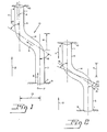
- Fig.'s 1 and 2 1 is a coil-free single-pass, radiant conduit means for directing process fluid, preferably hydrocarbon process fluid, therewithin (as indicated, for example, by arrows 2, 3 and 4) through the radiant section of a fired heater, preferably a hydrocarbon (pyrolysis) cracking furnace, in a once-through manner.
- radiant conduit means 1 could have any cross-sectional configuration, a tubular conduit wherein the cross-sectional configuration is circular is preferred.
- conduit means could have a constant cross-sectional flow area throughout its length or a swage configuration in which the cross-sectional flow area gradually increases from the inlet to the outlet, e.g., inlet inside diameter of 2.0 inches (5.08 cm) and outlet inside diameter of 2.5 inches (6.35 cm).
- This radiant conduit means has a first conduit section 5, preferably a low inlet section through which hydrocarbon process fluid flows in use in a first direction 2, and a second conduit section 6, - through which the fluid flows in use in a second direction 4.
- These sections are, preferably substantially straight.
- Directions 2 and 4 are, preferably, substantially the same; as shown both are upward. Most preferably these directions are substantially mutually parallel.
- inlet section 5 and outlet section 6 are each rigidly attached to elements 9 and 10.
- Element 9 is, preferably, an inlet manifold for distribution of hydrocarbon process fluid to a plurality of radiant conduit means 1 rigidly connected thereto.
- Element 10 could be an outlet manifold for heated hydrocarbon process fluid or a transfer line heat exchanger for cooling said fluid.
- inlet manifold is a "floating" inlet manifold to provide for absorption of the overall thermal growth of the corresponding coil (row of tubes).
- inlet manifold is a "floating" inlet manifold to provide for absorption of the overall thermal growth of the corresponding coil (row of tubes).
- sections 5 and 6 can either move toward each other, or longitudinally distort (as from a straight to bent configuration), in response to differential thermal expansions experienced during furnace operation. This movement of sections 5 and 6 toward each other is indicated by arrows 11 and 12. To provide for absorption of this thermal growth without significant distortion of the conduit means, offset 13 is provided, preferably within the radiant section of the furnace.
- Offset 13 comprises fluid flow conduit interconnecting means 14 which interconnects sections 5 and 6 in fluid flow communication and offsets these sections transversely 15 and longitudinally 16.
- "longitudinal offset” requires that the ends of section 5 and 6 closest to each other be separated by some distance.
- This offset can e.g., have a transverse length 15 of up to about 10% of the respective overall tube length within the radiant section. For example, an offset of 15 to 20 inches (38.1-50.8 cm) for a tube of about 30 feet (9.14 m) would be satisfactory.
- FIG. 1 illustrates a radiant conduit means 1 according to the present invention before the furnace is fired up and, thus, before the conduit means experiences thermal growth.
- Fig. 2 illustrates the radiant conduit means 1 of Fig. 1, but as it exists during furnace operation when differential thermal growth is experienced.
- conduit sections 5 and 6 will "grow” toward each other, as indicated by arrows 11 and 12.
- angles 18 and 19 change (by increasing) and, thus, absorb thermal growth of conduit means 1.
- 20 in Fig.
- angles 18 and 19 should be kept within limits. If these angles are too small before furnace operation, the radiant conduit means will be too straight and lose its ability to self-absorb thermal growth along these angles in a manner to avoid rupture of welds and tube distortions.
- the minimum angle is preferably about 10°. A minimum angle of about 20° is more preferred.
- the maximum angles are preferably about 75°. The more preferred maximum is about 60°.
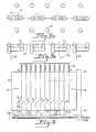
- the once-through radiant conduit means 1 in the form of radiant tubes, in at least one row and in parallel to each other, as shown, for example, in Figs. 3a, 3b and 4.
- Burners 23 are arranged in rows along both sides of each row of radiant tubes 1.
- the distance from a row of burner flames to the corresponding row of radiant tubes is critical and most carefully selected, and it should be kept as constant throughout operation of the furnace as is feasible. It is, accordingly, most desirable to prevent, or at least minimize, the extent of radiant tube distortion, during furance operation, toward the burners.
- any given coil (row) of tubes the offsets, preferably lie substantially in a common plane, most preferably in the plane of the coil 24. This imparts to the individual tubes in any given row the predisposition to bend during furnace operation along the coil plane and, thus, in a direction parallel to the row(s) of burners.
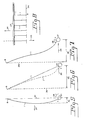
- the radiant tubes are preferably at least partially bowed (Fig. 5) in a direction 33 away from the coil plane 24.
- this direction is preferably the same for all radiant tubes in a given row, that is, it is preferred that all radiant tubes in a given row be at least partially bowed in the same direction away from the coil plane.
- the preferred bow direction is at an angle of 90° (26). By virtue of this bend, any distortion of the radiant tubes in a given row will tend to be in the same direction toward- the burners, thus avoiding shielding or touching of adjacent tubes.
- the bowing of the tubes can be accomplished by simple means.
- the radiant tubes in any given row are all rigidly attached both at their inlet ends 7, to a common inlet manifold 27 (Fig. 4) and at their outlet ends 8, they can be bowed by simply rotating the inlet manifold, as indicated by arrow 28 (Figs. 4, 5 and 7).
- the resulting tubes will either be bowed along a portion of their respective lengths (Fig. 7) or throughout their respective lengths (Fig. 5).
- a row (coil) of radiant conduit means 1 arranged within a radiant section of a fired heater is schematically shown in Fig. 4.
- the process fluid is fed to the radiant tubes from common inlet manifold 27 to which each tube is rigidly attached at 7. In the case of hydrocarbon cracking, this process fluid has been preheated in a convection section of the furnace.
- the cracked process fluid After being radiantly heated within enclosure 29, in the instance of hydrocarbon cracking, the cracked process fluid is fed to receiving means, preferably directly to transfer line exchangers 32 for quenching to stop further reaction of the process fluid (reaction mixture). It is also possible to collect the heated process fluid in a common outlet manifold and then direct it downstream for further processing. e.g., distillation, stripping, etc. In either event, the tube outlets are rigidly connected at 8, either to the transfer line exchanger or to the common outlet manifold.
- the burners are, preferably floor mounted adjacent the radiant tube inlets.
- radiant tubes in accordance with the present invention can be either offset or both offset within a common plane and bowed out of the common plane to cope with thermal stresses experienced during furnace operation.
- the radiant tubes can optionally be at least partially "longitudinally skewed" out of the coil plane 24 (Fig. 8), as illustrated in Fig.'s 5-8.
- Longitudinally means along their respective lengths.
- Skw means that the radiant tubes at least partially extend out of a vertical coil plane 24 drawn through the outlets 8 of the tubes in a given row.
- the radiant tubes 1 can be skewed by bowing them out of vertical coil plane 24, preferably all in the same direction 33 out of the vertical coil plane. This bowing can be accomplished, for example, by rotating the inlet manifold 27 as shown at 28.
- the radiant tubes in a given row can be skewed by horizontal displacement 34 of their inlets out of the vertical coil plane.
- the tubes will distort thermally as shown by dotted line 1' during furnace operation.
- the radiant tubes 1 can, optionally, be both bowed and displaced. This is achieved by horizontal displacement of the inlets 7 and rotation of the inlet manifold.
- the tubes will be predisposed to distort thermally, that is, change their respective longitudinal configurations, along the direction 33 of the skew.
- the radiant tubes in any given row are, preferably, skewed in the same direction out of the vertical coil plane to avoid, or minimize, shielding or touching of adjacent tubes and uneven heat distribution.
- the amount of skew 35, as measured from the vertical coil plane to the furthest point along the tube away from the vertical coil plane, is preferably up to about 10% of the overall length of the tubes.
- the minimum is preferably about one-half of one inside tube diameter the minimum inside diameter for a swage tube.
- a "floating" inlet manifold 27, one that can move in order to absorb a substantial amount (at least 40%) of the overall coil growth, can be provided by virtue of its (fluid flow) interconnections with radiant conduit means 1 and cross-over conduit means "1" for conducting preheated process fluid from convection section 30' to radiant section 30.
- inlet manifold 27 can move downwardly as shown, for example, by the dashed lines in Fig. 9.
- the inlet manifold could be (and preferably is) connected to more than one cross-over pipe.
- any known support means such as a known counterweight mechanism, schematically indicated as 36 in Fig. 9.
- horizontal leg 1 "' could be added to each radiant conduit means 1, preferably outside radiant section 30. It is preferred that the floating inlet manifold be commonly connected to each radiant tube in a given row.
Landscapes
- Engineering & Computer Science (AREA)
- Chemical & Material Sciences (AREA)
- Physics & Mathematics (AREA)
- Thermal Sciences (AREA)
- Oil, Petroleum & Natural Gas (AREA)
- Mechanical Engineering (AREA)
- General Engineering & Computer Science (AREA)
- Chemical Kinetics & Catalysis (AREA)
- General Chemical & Material Sciences (AREA)
- Organic Chemistry (AREA)
- Production Of Liquid Hydrocarbon Mixture For Refining Petroleum (AREA)
- Physical Or Chemical Processes And Apparatus (AREA)
Applications Claiming Priority (2)
| Application Number | Priority Date | Filing Date | Title |
|---|---|---|---|
| US06/301,763 US4499055A (en) | 1981-09-14 | 1981-09-14 | Furnace having bent/single-pass tubes |
| US301763 | 1981-09-14 |
Publications (3)
| Publication Number | Publication Date |
|---|---|
| EP0074853A2 EP0074853A2 (en) | 1983-03-23 |
| EP0074853A3 EP0074853A3 (en) | 1983-08-31 |
| EP0074853B1 true EP0074853B1 (en) | 1986-01-29 |
Family
ID=23164761
Family Applications (1)
| Application Number | Title | Priority Date | Filing Date |
|---|---|---|---|
| EP82304853A Expired EP0074853B1 (en) | 1981-09-14 | 1982-09-14 | Furnaces |
Country Status (6)
| Country | Link |
|---|---|
| US (1) | US4499055A (cg-RX-API-DMAC7.html) |
| EP (1) | EP0074853B1 (cg-RX-API-DMAC7.html) |
| JP (1) | JPS5870834A (cg-RX-API-DMAC7.html) |
| AU (1) | AU564730B2 (cg-RX-API-DMAC7.html) |
| CA (1) | CA1190169A (cg-RX-API-DMAC7.html) |
| DE (1) | DE3268839D1 (cg-RX-API-DMAC7.html) |
Families Citing this family (42)
| Publication number | Priority date | Publication date | Assignee | Title |
|---|---|---|---|---|
| JPS62118146U (cg-RX-API-DMAC7.html) * | 1986-01-16 | 1987-07-27 | ||
| US5181990A (en) * | 1986-01-16 | 1993-01-26 | Babcock-Hitachi Kabushiki Kaisha | Pyrolysis furnace for olefin production |
| DE3605415A1 (de) * | 1986-02-20 | 1987-08-27 | Katec Betz Gmbh & Co | Verfahren und vorrichtung zum verbrennen oxidierbarer bestandteile in einem traegergas |
| US4762958A (en) * | 1986-06-25 | 1988-08-09 | Naphtachimie S.A. | Process and furnace for the steam cracking of hydrocarbons for the preparation of olefins and diolefins |
| US5409675A (en) * | 1994-04-22 | 1995-04-25 | Narayanan; Swami | Hydrocarbon pyrolysis reactor with reduced pressure drop and increased olefin yield and selectivity |
| FR2795022A1 (fr) * | 1999-06-21 | 2000-12-22 | Michelin Soc Tech | Ensemble d'un pneumatique, d'une jante et d'un adaptateur |
| US6767375B1 (en) * | 1999-08-25 | 2004-07-27 | Larry E. Pearson | Biomass reactor for producing gas |
| US6339182B1 (en) | 2000-06-20 | 2002-01-15 | Chevron U.S.A. Inc. | Separation of olefins from paraffins using ionic liquid solutions |
| US20020103406A1 (en) | 2001-02-01 | 2002-08-01 | Georges Mathys | Production of olefin dimers and oligomers |
| US6875899B2 (en) * | 2001-02-01 | 2005-04-05 | Exxonmobil Chemical Patents Inc. | Production of higher olefins |
| US6849774B2 (en) * | 2001-12-31 | 2005-02-01 | Chevron U.S.A. Inc. | Separation of dienes from olefins using ionic liquids |
| US20030127358A1 (en) * | 2002-01-10 | 2003-07-10 | Letzsch Warren S. | Deep catalytic cracking process |
| US20030147604A1 (en) * | 2002-02-01 | 2003-08-07 | Tapia Alejandro L. | Housing assembly for providing combined electrical grounding and fiber distribution of a fiber optic cable |
| US20030209469A1 (en) * | 2002-05-07 | 2003-11-13 | Westlake Technology Corporation | Cracking of hydrocarbons |
| US7482502B2 (en) * | 2003-01-24 | 2009-01-27 | Stone & Webster Process Technology, Inc. | Process for cracking hydrocarbons using improved furnace reactor tubes |
| US6668762B1 (en) | 2003-04-17 | 2003-12-30 | Parviz Khosrowyar | Indirect fired process heater |
| US7048041B2 (en) * | 2003-07-25 | 2006-05-23 | Stone & Webster Process Technology, Inc. | Systems and apparatuses for stabilizing reactor furnace tubes |
| US7128827B2 (en) * | 2004-01-14 | 2006-10-31 | Kellogg Brown & Root Llc | Integrated catalytic cracking and steam pyrolysis process for olefins |
| EP1561796A1 (en) * | 2004-02-05 | 2005-08-10 | Technip France | Cracking furnace |
| US7067597B2 (en) * | 2004-02-25 | 2006-06-27 | Exxonmobil Chemical Patents Inc. | Process of making polypropylene from intermediate grade propylene |
| GB0420971D0 (en) * | 2004-09-21 | 2004-10-20 | Imp College Innovations Ltd | Piping |
| US8029749B2 (en) * | 2004-09-21 | 2011-10-04 | Technip France S.A.S. | Cracking furnace |
| US7749462B2 (en) | 2004-09-21 | 2010-07-06 | Technip France S.A.S. | Piping |
| GB0604895D0 (en) * | 2006-03-10 | 2006-04-19 | Heliswirl Technologies Ltd | Piping |
| US8129576B2 (en) * | 2005-06-30 | 2012-03-06 | Uop Llc | Protection of solid acid catalysts from damage by volatile species |
| US7491315B2 (en) * | 2006-08-11 | 2009-02-17 | Kellogg Brown & Root Llc | Dual riser FCC reactor process with light and mixed light/heavy feeds |
| US20090022635A1 (en) * | 2007-07-20 | 2009-01-22 | Selas Fluid Processing Corporation | High-performance cracker |
| GB0817219D0 (en) | 2008-09-19 | 2008-10-29 | Heliswirl Petrochemicals Ltd | Cracking furnace |
| US8684384B2 (en) * | 2009-01-05 | 2014-04-01 | Exxonmobil Chemical Patents Inc. | Process for cracking a heavy hydrocarbon feedstream |
| NO333597B1 (no) * | 2009-07-15 | 2013-07-15 | Fmc Kongsberg Subsea As | Undervannskjoler |
| US9011620B2 (en) * | 2009-09-11 | 2015-04-21 | Technip Process Technology, Inc. | Double transition joint for the joining of ceramics to metals |
| US8309776B2 (en) * | 2009-12-15 | 2012-11-13 | Stone & Webster Process Technology, Inc. | Method for contaminants removal in the olefin production process |
| US8747765B2 (en) | 2010-04-19 | 2014-06-10 | Exxonmobil Chemical Patents Inc. | Apparatus and methods for utilizing heat exchanger tubes |
| US10415820B2 (en) | 2015-06-30 | 2019-09-17 | Uop Llc | Process fired heater configuration |
| CA2912061C (en) | 2015-11-17 | 2022-11-29 | Nova Chemicals Corporation | Radiant for use in the radiant section of a fired heater |
| KR102379113B1 (ko) | 2017-05-05 | 2022-03-25 | 엑손모빌 케미칼 패턴츠 인코포레이티드 | 탄화수소 처리용 열전달 튜브 |
| CA3087983A1 (en) | 2018-01-08 | 2019-07-11 | Swift Fuels, Llc | Processes for an improvement to gasoline octane for long-chain paraffin feed streams |
| US10941357B2 (en) | 2018-04-16 | 2021-03-09 | Swift Fuels, Llc | Process for converting C2—C5 hydrocarbons to gasoline and diesel fuel blendstocks |
| US12024685B2 (en) | 2018-12-20 | 2024-07-02 | Exxonmobil Chemical Patents Inc. | High pressure ethane cracking with small diameter furnace tubes |
| US20220002214A1 (en) | 2020-03-31 | 2022-01-06 | Swift Fuels, Llc | Process for converting c2-c5 hydrocarbons to gasoline and diesel fuel blendstocks |
| US12435016B2 (en) | 2022-07-28 | 2025-10-07 | Chevron Phillips Chemical Company Lp | Flexible benzene production via selective-higher-olefin oligomerization of ethylene |
| WO2025122148A1 (en) | 2023-12-06 | 2025-06-12 | Chevron Phillips Chemical Company Lp | Flexible production of benzene and derivatives thereof via oligomerization of ethylene |
Family Cites Families (19)
| Publication number | Priority date | Publication date | Assignee | Title |
|---|---|---|---|---|
| US1788386A (en) * | 1928-03-29 | 1931-01-13 | Elliott Co | Heat exchanger |
| US1894279A (en) * | 1930-03-24 | 1933-01-17 | Westinghouse Electric & Mfg Co | Condenser |
| US2323498A (en) * | 1941-06-16 | 1943-07-06 | Universal Oil Prod Co | Heating of fluids |
| GB570115A (en) * | 1942-07-29 | 1945-06-22 | Westinghouse Electric Int Co | Improvements in or relating to heat-exchange apparatus |
| US2479544A (en) * | 1945-12-14 | 1949-08-16 | Lummus Co | Tubular heater |
| US2587720A (en) * | 1946-03-11 | 1952-03-04 | Lawrence H Fritzberg | Heat exchange device |
| US2917564A (en) * | 1959-01-05 | 1959-12-15 | Phillips Petroleum Co | Hydrocarbon cracking furnace and its operation |
| US3195989A (en) * | 1962-07-09 | 1965-07-20 | Foster Wheeler Corp | Integral tube furnace and oxidizer |
| NL295809A (cg-RX-API-DMAC7.html) * | 1962-07-30 | |||
| US3230052A (en) * | 1963-10-31 | 1966-01-18 | Foster Wheeler Corp | Terraced heaters |
| US3258067A (en) * | 1964-06-01 | 1966-06-28 | Fleur Corp | Heat exchanger |
| US3450506A (en) * | 1964-07-23 | 1969-06-17 | Lummus Co | Apparatus for the production of hydrogen |
| US3407789A (en) * | 1966-06-13 | 1968-10-29 | Stone & Webster Eng Corp | Heating apparatus and process |
| US3495556A (en) * | 1968-07-03 | 1970-02-17 | Dorr Oliver Inc | Heat exchanger of the tube bundle type |
| US3583476A (en) * | 1969-02-27 | 1971-06-08 | Stone & Webster Eng Corp | Gas cooling apparatus and process |
| US3607130A (en) * | 1969-09-24 | 1971-09-21 | Exxon Research Engineering Co | Reformer furnace |
| US3820955A (en) * | 1970-01-19 | 1974-06-28 | Stone & Webster Eng Corp | Horizontal high severity furnace |
| US3671198A (en) * | 1970-06-15 | 1972-06-20 | Pullman Inc | Cracking furnace having thin straight single pass reaction tubes |
| DE2504010A1 (de) * | 1975-01-31 | 1976-08-05 | Ici Ltd | Verfahren und vorrichtung zur herstellung von olefinen |
-
1981
- 1981-09-14 US US06/301,763 patent/US4499055A/en not_active Expired - Lifetime
-
1982
- 1982-08-16 CA CA000409497A patent/CA1190169A/en not_active Expired
- 1982-09-13 AU AU88354/82A patent/AU564730B2/en not_active Expired
- 1982-09-14 JP JP57160739A patent/JPS5870834A/ja active Granted
- 1982-09-14 DE DE8282304853T patent/DE3268839D1/de not_active Expired
- 1982-09-14 EP EP82304853A patent/EP0074853B1/en not_active Expired
Also Published As
| Publication number | Publication date |
|---|---|
| EP0074853A2 (en) | 1983-03-23 |
| JPH0210693B2 (cg-RX-API-DMAC7.html) | 1990-03-09 |
| AU8835482A (en) | 1983-03-24 |
| EP0074853A3 (en) | 1983-08-31 |
| US4499055A (en) | 1985-02-12 |
| CA1190169A (en) | 1985-07-09 |
| JPS5870834A (ja) | 1983-04-27 |
| AU564730B2 (en) | 1987-08-27 |
| DE3268839D1 (en) | 1986-03-13 |
Similar Documents
| Publication | Publication Date | Title |
|---|---|---|
| EP0074853B1 (en) | Furnaces | |
| EP1136541B1 (en) | Internally finned U-shaped radiant coil | |
| US6852294B2 (en) | Alternate coke furnace tube arrangement | |
| EP1718717B1 (en) | Cracking furnace | |
| EP0047359B1 (en) | Heating hydrocarbons in a tubular heater | |
| EP1009784B1 (en) | Cracking furnace with radiant heating tubes | |
| CA2068235A1 (en) | Thermal cracking furnace and process | |
| US4999089A (en) | Cracking furnace | |
| US3820955A (en) | Horizontal high severity furnace | |
| US4412975A (en) | Fired process heater | |
| US20130034819A1 (en) | Delayed Coking Process | |
| WO2005068926A1 (en) | Enhanced radiant heat exchanger apparatus | |
| KR101599662B1 (ko) | 열 교환 장치 및 그 제조방법 | |
| TW202503202A (zh) | 用於從裂解氣體進行熱回收之方法及裝置 | |
| JPH0649868B2 (ja) | 炭化水素の熱分解炉 |
Legal Events
| Date | Code | Title | Description |
|---|---|---|---|
| PUAI | Public reference made under article 153(3) epc to a published international application that has entered the european phase |
Free format text: ORIGINAL CODE: 0009012 |
|
| 17P | Request for examination filed |
Effective date: 19820930 |
|
| AK | Designated contracting states |
Designated state(s): DE FR GB NL |
|
| PUAL | Search report despatched |
Free format text: ORIGINAL CODE: 0009013 |
|
| AK | Designated contracting states |
Designated state(s): DE FR GB NL |
|
| GRAA | (expected) grant |
Free format text: ORIGINAL CODE: 0009210 |
|
| AK | Designated contracting states |
Designated state(s): DE FR GB NL |
|
| ET | Fr: translation filed | ||
| REF | Corresponds to: |
Ref document number: 3268839 Country of ref document: DE Date of ref document: 19860313 |
|
| PLBE | No opposition filed within time limit |
Free format text: ORIGINAL CODE: 0009261 |
|
| STAA | Information on the status of an ep patent application or granted ep patent |
Free format text: STATUS: NO OPPOSITION FILED WITHIN TIME LIMIT |
|
| 26N | No opposition filed | ||
| PGFP | Annual fee paid to national office [announced via postgrant information from national office to epo] |
Ref country code: NL Payment date: 20010618 Year of fee payment: 20 |
|
| PGFP | Annual fee paid to national office [announced via postgrant information from national office to epo] |
Ref country code: GB Payment date: 20010807 Year of fee payment: 20 |
|
| PGFP | Annual fee paid to national office [announced via postgrant information from national office to epo] |
Ref country code: FR Payment date: 20010831 Year of fee payment: 20 |
|
| PGFP | Annual fee paid to national office [announced via postgrant information from national office to epo] |
Ref country code: DE Payment date: 20010927 Year of fee payment: 20 |
|
| REG | Reference to a national code |
Ref country code: GB Ref legal event code: IF02 |
|
| PG25 | Lapsed in a contracting state [announced via postgrant information from national office to epo] |
Ref country code: GB Free format text: LAPSE BECAUSE OF EXPIRATION OF PROTECTION Effective date: 20020913 |
|
| PG25 | Lapsed in a contracting state [announced via postgrant information from national office to epo] |
Ref country code: NL Free format text: LAPSE BECAUSE OF EXPIRATION OF PROTECTION Effective date: 20020914 |
|
| REG | Reference to a national code |
Ref country code: GB Ref legal event code: PE20 Effective date: 20020913 |
|
| NLV7 | Nl: ceased due to reaching the maximum lifetime of a patent |
Effective date: 20020914 |