EP0074088B1 - Electromotive actuating drive for valves or the like - Google Patents
Electromotive actuating drive for valves or the like Download PDFInfo
- Publication number
- EP0074088B1 EP0074088B1 EP82108066A EP82108066A EP0074088B1 EP 0074088 B1 EP0074088 B1 EP 0074088B1 EP 82108066 A EP82108066 A EP 82108066A EP 82108066 A EP82108066 A EP 82108066A EP 0074088 B1 EP0074088 B1 EP 0074088B1
- Authority
- EP
- European Patent Office
- Prior art keywords
- handwheel
- valve stem
- nut
- stops
- disposed
- Prior art date
- Legal status (The legal status is an assumption and is not a legal conclusion. Google has not performed a legal analysis and makes no representation as to the accuracy of the status listed.)
- Expired
Links
Images

Classifications
-
- F—MECHANICAL ENGINEERING; LIGHTING; HEATING; WEAPONS; BLASTING
- F16—ENGINEERING ELEMENTS AND UNITS; GENERAL MEASURES FOR PRODUCING AND MAINTAINING EFFECTIVE FUNCTIONING OF MACHINES OR INSTALLATIONS; THERMAL INSULATION IN GENERAL
- F16K—VALVES; TAPS; COCKS; ACTUATING-FLOATS; DEVICES FOR VENTING OR AERATING
- F16K31/00—Actuating devices; Operating means; Releasing devices
- F16K31/02—Actuating devices; Operating means; Releasing devices electric; magnetic
- F16K31/04—Actuating devices; Operating means; Releasing devices electric; magnetic using a motor
- F16K31/047—Actuating devices; Operating means; Releasing devices electric; magnetic using a motor characterised by mechanical means between the motor and the valve, e.g. lost motion means reducing backlash, clutches, brakes or return means
- F16K31/048—Actuating devices; Operating means; Releasing devices electric; magnetic using a motor characterised by mechanical means between the motor and the valve, e.g. lost motion means reducing backlash, clutches, brakes or return means with torque limiters
Definitions
- the invention relates to an electromotive actuator drive for valves, slides or the like.
- torque-dependent end position switch-off of the closure piece arranged on a valve rod by means of an end on a plate spring or the like.
- Spring-loaded lifting spindle arranged switching element which acts on the limit switch, as well as with a handwheel serving as a spindle nut and surrounding the lifting spindle, which serves as a coupling and as a rotation lock for the valve rod.
- actuator drives known from DE-U-72 37 949 the electric motor of the drive, the lifting spindle of which is coupled to an rotatable rod, is switched in good time when the end days of the closure piece are reached.
- this advantageous design shows the disadvantage that no intermediate positions of the closure piece can be set with such an end position switch-off in order to allow a certain part of the medium to pass through.
- the object of the invention is therefore to improve an actuator drive of the aforementioned type in such a way that the closure piece can be set to different intermediate positions in a structurally simple manner and safely without changing the limit switch (closed or fully open position), the intermediate positions in their Setting should be controllable and adjustable from the outside.
- this object is achieved in a generic actuator drive in that two additional, limit the path of the valve rod in an upper and / or lower intermediate position and parallel to or in the direction of movement arranged path-dependent stops, which can be changed from the outside on or in part open valve structure are arranged, are provided.
- the housing is interrupted e.g. partially open to the outside due to cage-like design, so that the stops can be checked and / or easily changed by hand.
- stops are designed to be adjustable by displacement or twisting, any intermediate positions can be set in a simple manner.
- a housing 12 designed as a cage for the actuator drive is fastened to a three-way valve 10 with a closure piece 11 such as a valve plate or valve cone.
- a non-rotatable valve rod 13 arranged on the closure piece 11 projects into the valve structure or the housing 12 and is fastened at the end to a disk-shaped handwheel 14 acting as a spindle nut that is T-shaped in cross section.
- a threaded bore 16 is incorporated centrally in an extension 15 of this handwheel 14 and in the extension of the valve rod 13, into which a rotatable lifting spindle 17 with an external thread 16 is screwed.
- This lifting spindle 17 passes through a pot-shaped housing 19 in which a plurality of annular disks 20 comprising the lifting spindle 17 are arranged, one under the washer 20 being supported on the pot-shaped housing base 19 and an upper washer 20 on a screwed-on cover 21 which closes the housing 19.
- the middle two ring disks 20, which divide the interior of the housing 19 into two chambers 22, in each of which two plate springs 23 are arranged, which surround the lifting spindle 17, are axially limited on the lifting spindle 17 by means of a cotter pin 24, socket pins or the like stored and compress the plate springs 23 in the axial direction to trigger the switching process.
- a larger gear 25 comprises the lifting spindle 17 and meshes with a smaller gear 26, which can be driven by an electric motor 27.
- the transmission space 28 provided in the housing 12 for receiving the two gears is also closed by a removable cover 29 through which the upper end of the lifting spindle 17 is passed.
- a rotary disk 30 At the free end of this lifting spindle 17 outside the housing 12, there is a rotary disk 30, which is rotated alternately to the left or right when the lifting spindle 17 rotates and actuates an upper or lower limit switch 31 attached to the housing 12 during the axial displacement of the lifting spindle 17 which the electric motor 27 is switched as soon as the closure piece 11 has reached one of its end positions.
- valve rod 13 moves up and down without rotation, the handwheel 14 being secured against unintentional rotation by means of a spring-loaded locking bolt 32, the free end of which can be pulled out into a longitudinal groove 33 in the handwheel 14.
- This locking bolt 32 is mounted in a housing 32a, which is screwed into the webs 35 of the valve assembly 12 by means of a thread at right angles to the lifting spindle 17 and accommodates a spring 32b in the interior.
- the spring 32b presses with one end of the spring onto an annular shoulder 32c located on the locking pin 32, while the other end of the spring presses against a clamping ring 32d fastened in the housing 32a, so that the locking pin 32 is always pressed in the direction of the longitudinal groove 33.
- the handwheel 14 is to be adjusted in height, the locking bolt 32 is pulled out of the longitudinal groove 33 by means of a knurled disk 32e.
- the handwheel 14 is free and can be turned until the desired height is reached and the locking bolt 32 can snap back into place.
- the housing 32a is provided on the outside with a vertical slot 32f, into which a pin 32g fastened on the locking pin 32 in the region of the knurled disk 32e engages, which pin 32g is held so that it can be pulled out of the slot 32f is (see Fig. 3).
- the stroke limitation of the valve rod 13 is, instead of the stops 37.38, of a nut 39 connecting the valve rod 13 to the handwheel 14 and an adjustable nut 41 on a threaded attachment 40 enclosing the valve rod 13, with the same design in one direction and formed by a screwed onto the pot-shaped housing 19 and adjustable nut 42 in another direction.
- the stroke of the handwheel 14 is limited in the axial direction by correspondingly turning the nuts 41, 42.
- valve assembly 12 Since the valve assembly 12 is designed as a cage and thus partially open, the nuts 39.41 and 42 acting as stops can also be checked in their position and their position can be changed slightly from the outside.
- any intermediate position for the closure piece 11 can be selected.
- the handwheel 14 can be turned by hand after the locking bolt 32 has been pulled out in such a way that the closure piece 11 also reaches its desired end position in order to open or close the valve in whole or in part.
Description
Die Erfinding bezieht sich auf einen elektromotorischen Stellgliedantrieb für Ventile, Schieber od. dgl. mit drehmomentabhängiger Endlagenabschaltung des an einer Ventilstange angeordneten Verschlußstückes mittels eines endseitig an einer mittels Tellerfedern od.dgl. abgefederten Hubspindel angeordneten Schaltgliedes, das auf Endschalter einwirkt, sowie mit einem als Spindelmutter dienenden, die Hubspindel umgebenden Handrad das als Kupplung und als Drehsicherung für die Ventilstange, dient Bei derartiger z.B. aus DE-U-72 37 949 bekannten Stellgliedantrieben wird bei Erreichen der Endtagen des Verschlußstückes der Elektromotor des Antriebs, dessen Hubspindel mit einer undrehbaren Stange gekuppelt ist, rechtzeitig geschaltet. Diese an sich vorteilhafte Ausbildung zeigt jedoch den Nachteil, daß mit einer solchen Endlagenabschaltung keine Zwischenstellungen des Verschlußstückes eingestellt werden können, um noch einen gewissen Teil des Mediums durchzulassen.The invention relates to an electromotive actuator drive for valves, slides or the like. With torque-dependent end position switch-off of the closure piece arranged on a valve rod by means of an end on a plate spring or the like. Spring-loaded lifting spindle arranged switching element, which acts on the limit switch, as well as with a handwheel serving as a spindle nut and surrounding the lifting spindle, which serves as a coupling and as a rotation lock for the valve rod. actuator drives known from DE-U-72 37 949, the electric motor of the drive, the lifting spindle of which is coupled to an rotatable rod, is switched in good time when the end days of the closure piece are reached. However, this advantageous design shows the disadvantage that no intermediate positions of the closure piece can be set with such an end position switch-off in order to allow a certain part of the medium to pass through.
Aufgabe der Erfindung ist es daher, einen Stellgliedantrieb der vorgenannten Gattung dahingehend zu verbessern, daß das Verschlußstück in konstruktionsmäßig einfacher Weise und sicher auf unterschiedliche Zwischenstellungen eingestellt werden kann, ohne dabei die Endschaltung (Schließ- oder Ganzoffenstellung) zu verändern, wobei die Zwischenstellungen in ihrer Einstellung von außen kontrollierbar und einstellbar sein sollen.The object of the invention is therefore to improve an actuator drive of the aforementioned type in such a way that the closure piece can be set to different intermediate positions in a structurally simple manner and safely without changing the limit switch (closed or fully open position), the intermediate positions in their Setting should be controllable and adjustable from the outside.
Gemäß der Erfindung wird diese Aufgabe bei einem gattungsgemäßen Stellgliedantrieb dadurch gelöst, daß zwei zusätzliche, den Weg der Ventilstange in einer oberen und/oder unteren Zwischenstellung begrenzende und parallel zu bzw. in deren Bewegungsrichtung angeordnette wegabhängige Anschläge, die von außen lageveränderbar am oder im teilweise offenen Ventilaufbau angeordnet sind, vorgesehen sind.According to the invention, this object is achieved in a generic actuator drive in that two additional, limit the path of the valve rod in an upper and / or lower intermediate position and parallel to or in the direction of movement arranged path-dependent stops, which can be changed from the outside on or in part open valve structure are arranged, are provided.
Diese Auschläge sind in ihrer Ausbildung einfach und halten in ihrer Wirkungsweise sicher das Verschlußstück in Zwischenstellungen (zwischen Zu und Ganzoffen.) Dabei kommt die drehmomentabhängige Schaltung des Antriebes auch voll zur Auswirkung. Dazu ist das Gehäuse durch Unterbrechungen z.B. durch käfigarte Ausbildung teilweise (nach außen) offen, so daß die Anschläge einerseits kontrolliert und/oder andererseits leicht von Hand verändert werden können.These deflections are simple in their design and hold the closure piece in intermediate positions (between closed and fully open.) The torque-dependent switching of the drive also comes into full effect. For this purpose the housing is interrupted e.g. partially open to the outside due to cage-like design, so that the stops can be checked and / or easily changed by hand.
Sofern bei einer bevorzugten Ausführungform diese Anschläge verstellbar durch Verschieben oder Verdrehen ausgebildet sind, so können beliebige Zwischenstellungen in einfacher Weise eingestellt werden.If, in a preferred embodiment, these stops are designed to be adjustable by displacement or twisting, any intermediate positions can be set in a simple manner.
Weitere Merkmale der Erfindung sind in den Unteransprüchen aufgeführt.Further features of the invention are listed in the subclaims.
Auf den Zeichnungen sindOn the drawings are
Ausführungsbeispiele der Erfindung dargestellt. Es zeigen:
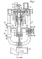
- Fig. 1 eine Seitenansicht mit teilweisem senkrechten Schnitt eines Stellgliedantriebes;
- Fig. 2 eine Seitenansicht mit teilweisem senkrechten Schnitt einer abgeänderten Ausführung eines Stellgliedantriebes und
- Fig. 3 einen senkrechten Schnitt eines abgeänderten, den Feststellbolzen aufnehmenden Gehäuses.
- Figure 1 is a side view with a partial vertical section of an actuator drive.
- Fig. 2 is a side view with partial vertical section of a modified version of an actuator drive and
- Fig. 3 is a vertical section of a modified, the locking bolt receiving housing.
An einem Dreiwegeventil 10 mit einem Verschlußstück 11 wie Ventilteller oder Ventilkegel ist ein als Käfig ausgebildetes Gehäuse 12 für den Stellgliedantrieb befestigt.A
Eine an dem Verschlußstück 11 angeordnete, nicht drehbare Ventilstange 13 ragt in den Ventilaufbau oder das Gehäuse 12 hinein und ist endseitig an einem scheibenförmigen Handrad 14 als Spindelmutter wirkend befestigt, daß im Querschnitt T-förmig ausgebildet ist. Zentrisch in einem Ansatz 15 dieses Handrades 14 und in Verlängerung der Ventilstange 13 ist eine Gewindebohrung 16 eingearbeitet, in die eine drehbare Hubspindel 17 mit Außengewinde 16 eingeschraubt ist. Diese Hubspindel 17 durchfasß topfförmiges Gehäuse 19, in dem mehrere, die Hubspindel 17 umfassende Ringscheiben 20 angeordnet sind, wobei eine unter Ringscheibe 20 sich am topfförmigen Gehäuseboden 19 und eine obere Ringscheibe 20 an einem aufgeschraubten, das Gehäuse 19 schließenden Deckel 21 abstützt. Die mittleren beiden Ringscheiben 20, die den Innenraum des Gehäuse 19 in zwei Kammern 22 unterteilen, in denen jeweils zwei Tellerfedern 23 angeordnet sind, welche die Hubspindel 17 umgeben, sind mittels eines Splintes 24, Steckbolzen od. dgl. auf der Hubspindel 17 axial begrenzt gelagert und drücken die Tellerfedern 23 in axialer Richtung zum Auslösen des Schaltvorganges zusammen. Oberhalb dieses Gehäusetopfes 19, der durch einen abnehmbaren Deckel 21 abgedeckt ist, umfaß ein größeres Zahnrad 25 die Hubspindel 17 und kämmt mit einem kleineren Zahnrad 26, das von einem E-Motor 27 angetrieben werden kann.A
Der ober im Gehäuse 12 zur Aufnahme der beiden Zahnräder vorgesehene Getrieberaum 28 ist ebenfalls durch einen abnehmbaren Deckel 29 abgeschlossen, durch den das obere Ende der Hubspindel 17 hindurchgeführt ist. Am freien Ende dieser Hubspindel 17 außerhalb des Gehäuses 12 lagert eine Rotationsscheibe 30, die bei Drehbewegung der Hubspindel 17 wechselweise links bzw. rechts verdreht wird und bei der axialen Verschiebung der Hubspindel 17 einen oberen bzw. unteren am Gehäuse 12 befestigten Endschalter 31 betätigt, durch den der E-Motor 27 geschaltet wird, sobald das Verschlußstück 11 eine seiner Endlagen erreicht hat.The
Mit der motorischen Drehung der Hubspindel 17 bewegt sich dazu die Ventilstange 13 ohne Drehung nach unten bzw. oben, wobei das Handrad 14 gegen unbeabsichtigte Drehung mittels eines federnd gelagerten Feststellbolzens 32 festgelegt ist, dessen freies Ende in eine Längsnut 33 des Handrades 14 herausziehbar einfaßt.With the motorized rotation of the
Dieser Feststellbolzen 32 lagert in einem Gehäuse 32a, das rechtwinklig zur Hubspindel 17 in einem den Stege 35 des Ventilaufbaues 12 mittels Gewinde eingeschraubt ist und im Inneren eine Feder 32b aufnimmt. Die Feder 32b drückt einerseits mit einem Federende auf einen am Feststellbolzen 32 befindlichen Ringansatz 32c, während das andere Federende gegen einen im Gehäuse 32a befestigten Spannring 32d drückt, so daß der Feststellbolzen 32 stets in Richtung Längsnut 33 gedrückt ist. Soll das Handrad 14 in der Höhe verstellt werden, so wird der Feststellbolzen 32 mittels einer Rändelscheibe 32e aus der Längsnut 33 herausgezogen. Das Handrad 14 ist frei und kann so weit verdreht werden, bis die gewünschte Höhe erreicht ist und der Feststellbolzen 32 wieder einrasten kann.This
Um den Feststellbolzen 32 radial in seiner Lage zu halten, ist das Gehäuse 32a außenseitig mit einem senkrechten Schlitz 32f versehen, in den ein am Feststellbolzen 32 im Bereich der Rändelscheibe 32e befestigter Stift 32g eingreift, der mit dem Feststellbolzen 32 aus dem Schlitz 32f herausziehbar gehalten ist (vergl. Fig. 3).In order to hold the
Wenn das Verschlußstück 11 in seiner Endstellung auf dem Ventilsitz aufliegt, ist der Verschiebeweg der Ventilstange 13 nach unten beendet, so daß die Hubspindel 17 nach oben bewegt wird. Durch die axiale Verschiebung der Hubspindel 17 drückt die mittlere Ringscheibe 20 der Hubspindel 17 die oberen Tellerfedern 23 zusammen, wobei die Rotationsscheibe 30 den oberen Schaltstift 34 des Endschalters 31 betätigt und den Motor 27 abschaltet. Der Schaltvorgang in Öffnungsstellung des Verschlußstückes 11 erfolgt in umgekehrtem Sinne. Die mittlere Ringscheibe 20 drückt dabei auf die unteren Tellerfedern23, wobei die Rotaionsscheibe 30 den unteren Schaltstift 34 betätigt und den Motor 27 schaltet.When the closure piece 11 rests on the valve seat in its end position, the displacement of the
Die Vorteile einer solchen drehmomentabhängigen Ausbildung und Schaltung durch Zwischenschaltung der Tellerfedern 23 liegen einerseits darin, daß der Ventilhub nicht genau eingestellt zu werden braucht und andererseits bei Vorhandensein eines Fremdkörpers zwischen Ventilsitz und Verschlußstück 11 der Antrieb ohne Erreichen seiner Endstellung zunächst abgeschaltet wird.The advantages of such a torque-dependent design and switching by interposing the
Diese an sich bekannte Ausführung wird verbessert durch eine gesonderte wegabhängige Schaltanordnung. Dazu sind an einem steg 35 als Käfig ausgestalteten (d.h. teilweise offenen) Gehäuses 12 in gewissem Abstande ein oberer mittels Schraube 36 od.dgl. verstellbarer Anschlag 37 und ein entsprechender unterer verstellbarer Anschlag 38 gelagert. Diese Anschläge 37, 38 haben die Aufgabe, daß das Verschlußstück 11 innerhalb des Hubbereiches jede Zwischenstellung einnehmen kann, z.B. bei gewissen Gasarmaturen, bei denen eine kleinere Gasmenge zum Aufrechterhalten der Zündflamme gewährleistet sein muß. Auch ist es oftmals notwendig bei Ventilen nicht die volle Gasmenge durchzulassen, so daß das Verschlußstück 11 bei Erreichen eines gewissen Hubes der Hubspindel (wegabhängig) stillgesetzt werden muß.This known design is improved by a separate travel-dependent switching arrangement. For this purpose, on a
Sobald die obere oder untere Fläche des Handrades 14 den einen oder anderen seitlichen Anschlag 37, 38 berührt, hält die Ventilstange 13 an, während sich die Hubspindel 17 noch unter Einhaltung der gewünschten Schließkraft mittels der Tellerfedern 23 bewegt, bis der eine oder andere Schaltstift 34 betätigt wird, so daß dann erst der E-Motor 27 stillsteht.As soon as the upper or lower surface of the
Bei dem Ausführungsbeispiel gemäß Fig. 2 der Zeichnung ist bei sonstiger gleicher Ausbildung die Hubbegrenzung der Ventilstange 13 anstelle der Anschläge 37.38 von einer die Ventilstange 13 mit dem Handrad 14 verbindenden Mutter 39 und einer, auf einem die Ventilstange 13 umschließenden Gewindeansatz 40, einstellbarer Mutter 41 in einer Richtung und von einer auf das topfförmige Gehäuse 19 aufgeschraubten und einstellbaren Mutter 42 in anderer Richtung gebildet. Durch entsprechendes Verdrehen der Muttern 41, 42 wird der Hubweg des Handrades 14 in axialer Richtung begrenzt.In the exemplary embodiment according to FIG. 2 of the drawing, the stroke limitation of the
Da der Ventilaufbau 12 als Käfig und damit teilweise offen ausgebildet ist, können ebenfalls die als Anschläge wirkenden Muttern 39.41 und 42 in ihrer Stellung überprüft und von außen leicht in ihrer Lage verändert werden.Since the
Durch Verstellen der Anschläge 37, 38,41,42 kann jede beliebige Zwischenstellung für das Verschlußstück 11 gewählt werden.By adjusting the
Sofern bei beiden Ausführungen der Antriebsmotor 27 ausfällt, kann das Handrad 14 nach Herausziehen des Feststellbolzens 32 derart von Hand gedreht werden, daß das Verschlußstück 11 ebenfalls seine gewünschte Endlage erreicht, um damit das Ventil ganz oder teilweise zu öffnen oder zu schließen.If the
Claims (4)
Applications Claiming Priority (2)
| Application Number | Priority Date | Filing Date | Title |
|---|---|---|---|
| DE3134820A DE3134820C2 (en) | 1981-09-03 | 1981-09-03 | Electromotive actuator drive for valves or the like. |
| DE3134820 | 1981-09-03 |
Publications (3)
| Publication Number | Publication Date |
|---|---|
| EP0074088A2 EP0074088A2 (en) | 1983-03-16 |
| EP0074088A3 EP0074088A3 (en) | 1984-03-28 |
| EP0074088B1 true EP0074088B1 (en) | 1986-05-21 |
Family
ID=6140730
Family Applications (1)
| Application Number | Title | Priority Date | Filing Date |
|---|---|---|---|
| EP82108066A Expired EP0074088B1 (en) | 1981-09-03 | 1982-09-02 | Electromotive actuating drive for valves or the like |
Country Status (2)
| Country | Link |
|---|---|
| EP (1) | EP0074088B1 (en) |
| DE (2) | DE3134820C2 (en) |
Families Citing this family (4)
| Publication number | Priority date | Publication date | Assignee | Title |
|---|---|---|---|---|
| DE19535051C1 (en) * | 1995-09-21 | 1996-11-28 | Honeywell Ag | Spindle nut or threaded spindle arrangement |
| DE19638216C1 (en) * | 1996-09-19 | 1997-11-20 | Honeywell Ag | Electric motor control element drive e.g. for valves |
| DE102004049180A1 (en) * | 2004-10-08 | 2006-04-13 | Bosch Rexroth Aktiengesellschaft | Valve has slide with electrical spindle drive which operates slide via magnetic lifting unit operated in pulsating manner, unit moving over part of slide path and spindle drive being reset when unit is returning to its original position |
| NO334421B1 (en) * | 2009-08-20 | 2014-03-03 | Vetco Gray Scandinavia As | Electrically operated valve actuator with electromechanical device for detecting end stops |
Citations (1)
| Publication number | Priority date | Publication date | Assignee | Title |
|---|---|---|---|---|
| DE7237949U (en) * | 1973-02-08 | Holter Regelarmaturen Gmbh & Co Kg | Electromotive actuator drive |
Family Cites Families (5)
| Publication number | Priority date | Publication date | Assignee | Title |
|---|---|---|---|---|
| DE912517C (en) * | 1951-06-09 | 1954-05-31 | Basf Ag | Valve or slide protection |
| DE1450824B1 (en) * | 1964-02-24 | 1970-01-29 | Siemens Ag | Screw gear with a motor-driven rotating nut |
| DE1550144B1 (en) * | 1966-12-08 | 1969-09-18 | Helmut Baelz Ges F Patentverwe | Motorized valve drive with manual intervention |
| DE1600697B1 (en) * | 1967-02-18 | 1970-01-29 | Helmut Baelz Ges Fuer Patentve | Motor valve drive with automatic end position switch-off |
| FR2244950B1 (en) * | 1973-09-21 | 1982-07-02 | Guilbert Fils Anciens Ets Leon |
-
1981
- 1981-09-03 DE DE3134820A patent/DE3134820C2/en not_active Expired
-
1982
- 1982-09-02 DE DE8282108066T patent/DE3271255D1/en not_active Expired
- 1982-09-02 EP EP82108066A patent/EP0074088B1/en not_active Expired
Patent Citations (1)
| Publication number | Priority date | Publication date | Assignee | Title |
|---|---|---|---|---|
| DE7237949U (en) * | 1973-02-08 | Holter Regelarmaturen Gmbh & Co Kg | Electromotive actuator drive |
Also Published As
| Publication number | Publication date |
|---|---|
| DE3134820A1 (en) | 1983-03-17 |
| EP0074088A3 (en) | 1984-03-28 |
| EP0074088A2 (en) | 1983-03-16 |
| DE3271255D1 (en) | 1986-06-26 |
| DE3134820C2 (en) | 1984-11-29 |
Similar Documents
| Publication | Publication Date | Title |
|---|---|---|
| DE1550639B1 (en) | ELECTROMOTORIC ACTUATOR FOR VALVES WITH A SPRING TENSION | |
| EP0578168A1 (en) | Valve | |
| EP0432440B1 (en) | Electrically actuated valve | |
| EP0688984A1 (en) | Diaphragm valve | |
| DE1285820B (en) | Control valve that can be switched to different operating modes | |
| DE3027181A1 (en) | Failsafe adjusting device | |
| DE3640302C2 (en) | Metering slide | |
| DE1550268B1 (en) | DIAPHRAGM VALVE FOR THE CONTROL OF A PRESSURE MEDIUM FLOW | |
| EP0074088B1 (en) | Electromotive actuating drive for valves or the like | |
| EP0195206B1 (en) | Pilot-operated valve | |
| EP0816730A2 (en) | Device for limiting the prestress of a control spring | |
| EP0429915A1 (en) | Electric operated valve and its use | |
| DE2416359A1 (en) | 2-way or multi-way valve, especially for aggressive media on the basis of plastic | |
| DE2334571A1 (en) | VALVE ACTUATOR | |
| EP0630452A1 (en) | Proportional distributing valve. | |
| DE2010431B1 (en) | Motorized actuator for valves with thrust-dependent end position shutdown | |
| DE4113019A1 (en) | Flap valve with rotatable and axially movable flap - has flap spindle, fixed for rotation with flap, mounted in housing bearings, that allow axial component of motion | |
| DE4447309C2 (en) | Control valve | |
| DE1750118C3 (en) | Valve or the like. with reversible pressure medium actuation | |
| DE2259868A1 (en) | SLIDE VALVE | |
| DE1426538A1 (en) | Servo control device | |
| DE1457530B2 (en) | GAS LIGHTER | |
| DE2241551A1 (en) | THROUGH VALVE | |
| DE2322940B1 (en) | MOTOR DRIVE IN PARTICULAR FOR CONTROL VALVES | |
| DE1199079B (en) | Flap valve |
Legal Events
| Date | Code | Title | Description |
|---|---|---|---|
| PUAI | Public reference made under article 153(3) epc to a published international application that has entered the european phase |
Free format text: ORIGINAL CODE: 0009012 |
|
| AK | Designated contracting states |
Designated state(s): CH DE FR GB IT LI SE |
|
| 17P | Request for examination filed |
Effective date: 19830913 |
|
| PUAL | Search report despatched |
Free format text: ORIGINAL CODE: 0009013 |
|
| AK | Designated contracting states |
Designated state(s): CH DE FR GB IT LI SE |
|
| GRAA | (expected) grant |
Free format text: ORIGINAL CODE: 0009210 |
|
| AK | Designated contracting states |
Kind code of ref document: B1 Designated state(s): CH DE FR GB IT LI SE |
|
| PG25 | Lapsed in a contracting state [announced via postgrant information from national office to epo] |
Ref country code: IT Free format text: LAPSE BECAUSE OF FAILURE TO SUBMIT A TRANSLATION OF THE DESCRIPTION OR TO PAY THE FEE WITHIN THE PRESCRIBED TIME-LIMIT;WARNING: LAPSES OF ITALIAN PATENTS WITH EFFECTIVE DATE BEFORE 2007 MAY HAVE OCCURRED AT ANY TIME BEFORE 2007. THE CORRECT EFFECTIVE DATE MAY BE DIFFERENT FROM THE ONE RECORDED. Effective date: 19860521 |
|
| PG25 | Lapsed in a contracting state [announced via postgrant information from national office to epo] |
Ref country code: SE Effective date: 19860531 |
|
| ET | Fr: translation filed | ||
| REF | Corresponds to: |
Ref document number: 3271255 Country of ref document: DE Date of ref document: 19860626 |
|
| PLBI | Opposition filed |
Free format text: ORIGINAL CODE: 0009260 |
|
| 26 | Opposition filed |
Opponent name: HOLTER REGELARMATUREN GMBH & CO. KG Effective date: 19870212 |
|
| GBPC | Gb: european patent ceased through non-payment of renewal fee | ||
| RDAG | Patent revoked |
Free format text: ORIGINAL CODE: 0009271 |
|
| STAA | Information on the status of an ep patent application or granted ep patent |
Free format text: STATUS: PATENT REVOKED |
|
| 27W | Patent revoked |
Effective date: 19890407 |
|
| REG | Reference to a national code |
Ref country code: CH Ref legal event code: PL |
|
| GBPR | Gb: patent revoked under art. 102 of the ep convention designating the uk as contracting state |