EP0073652A2 - Annular corrugator - Google Patents
Annular corrugator Download PDFInfo
- Publication number
- EP0073652A2 EP0073652A2 EP82304497A EP82304497A EP0073652A2 EP 0073652 A2 EP0073652 A2 EP 0073652A2 EP 82304497 A EP82304497 A EP 82304497A EP 82304497 A EP82304497 A EP 82304497A EP 0073652 A2 EP0073652 A2 EP 0073652A2
- Authority
- EP
- European Patent Office
- Prior art keywords
- tube
- die
- dies
- rib
- guide
- Prior art date
- Legal status (The legal status is an assumption and is not a legal conclusion. Google has not performed a legal analysis and makes no representation as to the accuracy of the status listed.)
- Withdrawn
Links
Images


Classifications
-
- B—PERFORMING OPERATIONS; TRANSPORTING
- B21—MECHANICAL METAL-WORKING WITHOUT ESSENTIALLY REMOVING MATERIAL; PUNCHING METAL
- B21D—WORKING OR PROCESSING OF SHEET METAL OR METAL TUBES, RODS OR PROFILES WITHOUT ESSENTIALLY REMOVING MATERIAL; PUNCHING METAL
- B21D15/00—Corrugating tubes
- B21D15/04—Corrugating tubes transversely, e.g. helically
- B21D15/06—Corrugating tubes transversely, e.g. helically annularly
Definitions
- the invention relates to the manufacture of corrugated metal hose from thin-walled, seamless or butt-welded smooth tubing, and more particularly, to the formation of annular corrugations in such tubing on a continuous basis.
- the invention is an improvement on the invention disclosed in our co-pending European Patent Application-A-0051454.
- helical metal hose can be manufactured on a continuous basis by either rotating a tube through annular die rings which themselves are free to rotate, or by rotating the die rings about a non-rotating tube.
- Another process for making helical corrugations uses tapered helical dies rotating about a drawn tube moving in a straight line.
- Annular metal hose is typically made by relatively slow procedures such as the internal bulging process and the external inward-forming process.
- the internal bulging process can produce excellent corrugation shapes, but operates at a relatively low speed and can only make relatively short lengths of corrugated tube.
- the process utilizes a solid rubber bung which is compressed to pre- bulge the tube after which the corrugation is formed by axial compression.
- the external inward-forming method depends on either preforming the tube by mechanical pressure using multi-finger type dies, or by pregrooving using a rotary planetary motion around the tube, both prior to forming of the corrugation by axial compression of the tube.
- US-A-3,656,331 discloses an apparatus that purports to produce annularly corrugated tubing with an annular die having an internal helical ridge of less than 360° extent and a pitch equal to the desired corrugation pitch of the finished tube.
- US-A-4,215,559 is related to US-A-3,656,331, but provides for the die ridge to have a maximum height for more than 360°.
- the depth of penetration is adjusted before the corrugating operation commences.
- the tube is driven axially without rotation through a guide in a predetermined relationship to the speed of rotation of a die carrier about the axis of the tube.
- EP-A-0051454 overcomes the problems of the prior art and permits continuous, annularly corrugated tubing to be produced.
- the apparatus utilizes a rolling carriage incorporating a motorized driving head to rotate the tube which in turn causes the synchronized annular dies to rotate.
- This type of drive is expensive, somewhat cumbersome, and limits the length of tube that can be processed since the turning torque induced by the driving head at the trailing end of the tube must be transmitted by the leading end of the tube to rotate the dies.
- the present invention seeks to provide an apparatus which can form metal hose having annular corrugations on a continuous basis and without leaving tool marks on the work which could weaken it or affect its appearance. Another aim is to form such corrugations in tubing having a very thin wall and of a diameter up to at least 150 to 200 mm.
- an apparatus which comprises a first annular die adapted to encompass the tube, said first die including a helical internal rib extending circumferentially at a predetermined internal diameter for at least 360° around the interior wall of said first die and adapted to indentably bear on the exterior of said tube in a substantially radial direction; at least a second annular die adapted to encompass the tube downstream of said first die, said second die including a helical internal rib which extends circumferentially for at least 360° at a predetermined internal diameter, the helical internal rib in said second die having a smaller thread pitch than the rib in said first die, means for incurring relative rotation between said tube and said dies whereby to axially displace said tube continually through said dies while simultaneously forming annular corrugations therein, and means for synchronizing the rotation of said dies so that they rotate at the same angular speed, and which is characterised in that a non-rotatable guide is fixedly positioned on
- each successive die has at least the principal portion of its helical rib at a closer or smaller pitch than the corresponding rib portion of the preceding die and that the ribs be dimensioned so as to progressively deepen the corrugations. It is desirable to have at least 360° of helical rib on each die and preferably several turns on the final dies so as to smooth out the corrugations and to increase the contact driving area between the dies and the tube.
- synchronized dies are rotated by virtue of the fact that the common shaft is driven by a motor.
- the rotating dies frictionally engage the tube and thereby produce a rotation of the tube. They also cause the tube to advance axially through the apparatus.
- this type of drive requires an initial driving rotation of the lead end of the tube until all of the sets of dies are in working contact with the tube, it eliminates the need to drive the trailing end of the tube.
- the tube can be very long, such as 60 metres or more, for example, and can be guided to the apparatus by a simple arcuate trough which is preferably lined with nylon or other low friction material to reduce drag on the rotating tube drawn axially through it.
- each successive die has a helical rib at a closer pitch than the corresponding rib of the preceding die, it is not essential in the situation where there are at least three annular dies in use and small diameter tubing is being produced which requires only a small amount of corrugating.
- the dies for forming 6.35 mm tubing might have, respectively, 1.58, 2.36, 2.36, 3.94 threads per cm (4, 6, 6, 10 threads per inch) while the dies for 38.1 mm tubing might have 1.38, 2.17, 2.76 and 3.14 threads per cm (3b, 5b, 7 and 8 t.p.i.).
- the two centre dies can be duplicates to save tooling cost and the second die with 2.36 t.p.c. would merely serve to transfer the tube, help maintain its driving relation with the other dies and maintain a radial pressure on the tube relative to the opposing pressure exerted on it by the immediately adjacent dies or tube guides.
- the annular dies from the second die to the penultimate die, inclusively, preferably have the first revolution of their helical rib formed at a pitch which is equal to or at least quite close to the pitch of the principal portion of the helical rib of the preceding die. This is easily accomplished by fitting an insert to the upstream or entrance end of each of these dies.
- the arrangement ensures that the corrugations formed by each die will be correctly guided into each succeeding die and will uniformly and gradually be compressed by the succeeding die, with no chance of the tube being cross-threaded.
- the dies could be formed so that the thread pitch of the rib changes uniformly within the die.
- apparatus according to the invention to corrugate tube of diameters of 50 mm or more from thin wall stock having a thickness of only 0.30 mm to 0.41 mm, for example, is dependent on providing the guide for the tube while it is in the first die to firmly engage those portions of the periphery of the tube which, in the absence of the guide, would be forced radially outwardly due to the pressure of the first die on the tube.
- the guide which is fixed, extends through and slightly beyond the first die and completely surrounds the tube except that it has a window in its periphery at one location so that the rib of the first die can contact the tube.
- the guide preferably has an internal diameter about 0.75 mm to 2.0 mm greater than the outer diameter of the tube and causes the tube to remain generally round, thus preventing its collapse.
- the fixed guide necessarily exerts a substantial contact force on the rotating, axially advancing tube, and thus is desirably made of a material which will provide good wear characteristics.
- Brass guides generally have a very limited wear life while tool steel guides sometimes have a tendency to seize the tube, which is generally made of stainless steel.
- a quite satisfactory material for the guide has been found to be an aluminum bronze alloy (e.g. that sold under the tradename Ampco No. 25).
- the various dies are preferably mounted so that they can be tilted, moved axially relative to the tube axis, or moved transversely of the tube axis.
- Axial movement of the dies relative to the tube can be achieved by rotation of one die relative to the next, by movement of die blocks supporting the dies relative to a base of the apparatus, or by a combination of both.
- the annular corrugating apparatus is indicated generally at 10 and shows a tube 11 inserted in the apparatus prior to the initiation of a corrugating operation.
- the apparatus 10 has a horizontal support base 12 carried by legs 12', a fixed front vertical support plate 13, movable front support plates 13', 13", and a plurality of axially transverse support plates 14, 16 and 18.
- Tube support bearings 20, 22, 24 are mounted in the plates 14-18 and an additional tube support bearing 26 is also provided.
- a non-rotating guide 28 extends outwardly from the housing of the bearing 22 and will be described in more detail in connection with Figure 2.
- Positioned between the bearings 20 and 22 are three die stages, the first of which comprises a first die block 30 and a second die block 32.
- the second stage comprises a third die block 34 and a fourth die block 36, while the third stage comprises a fifth die block 38 and a sixth die block 40.
- the number of die blocks provided can vary depending upon the diameter and range of tube sizes to be produced with the apparatus. However, we have found that three stages work satisfactorily.
- Each die block non-rotatably supports an annular die 30' to 40' formed on its inner surface with corrugating helical ribs 30" to 40", respectively.
- Power to drive the die blocks 30-40 is provided by a motor (not shown) which drives a small sprocket wheel 42 through a speed reducing drive mechanism 44.
- a chain 46 then drives a large sprocket wheel 48 which is fixed for rotation with a synchronizing shaft 52 mounted at the top of the apparatus 10.
- a plurality of sprocket drive chains 54 connect large sprockets 56, carried one by each die block, to small sprockets 58 which are mounted by bolts 59 on mounting heads 60 keyed to an idler shaft 52.
- Each small sprocket 58 has a ball joint mounting (not shown) within its mounting head 60 and each head 60 is non-rotatably keyed to a key slot 61 so it can move axially of the idler shaft 52.
- movements of the drive chains 54 which must take place as the die blocks 30-40 are tilted or moved axially, can be readily accommodated.
- Each of the die blocks 30-40 is mounted for tilting movement about a respective tilt shaft 64, and alternate die blocks are mounted for movement toward or away from the tube axis from either the front support wall 13 or a rear support wall 65 (see Figure 3).
- Shafts 66 in each die block can move in elongate slots 68 in the front or rear walls 13, 65 and are locked in varying positions of tilt adjustment by screw fasteners 70.
- the correct angle of tilt of any particular die block will be the angle at which the helical rib 30"-40" (see Figure 2) of the die in the die box will contact the tube 11 in a plane normal to the axis of tube 11. Since the dies in alternate die blocks, such as the die blocks 38 and 40, will contact the tube on the back and front side, respectively, of the ribs 38", 40", the pair of dies which form each stage must be tilted in opposite directions.
- each die rib 30"-40" into the tubing being corrugated is controlled by a feed device which could be mechanically, pneumatically, or hydraulically activated, but is shown in Figure 3 as a manually operable member 74.
- the member 74 rotates but does not move axially to turn a threaded portion 74' thereof which is engaged with an axially movable but non-rotatable nut member 75.
- the nut member 75 is pinned to the respective die block (in the case illustrated in Figure 3, the die block 38) by a pin 75'.
- Figure 3 also shows the mechanism 52-58 for synchronizing the rotation of the various die boxes.
- the corrugations produced by each upstream die be picked up by a lead-in portion of the die rib in a succeeding die.
- the corrugations lla should arrive at the die 32' so that they are exactly aligned with the lead-in segment of the die rib 32". This can be accomplished by slightly rotating the downstream die relative to the upstream die as required. Additional axial adjustment of the die blocks can be obtained by moving the vertical walls 13', 13", 65 relative to the base 12 and clamping them with clamp angles 95 and bolts 95'. In order to accommodate the in-and-out movement of the die blocks and the tilting of the die blocks, some slack is left in the chains 54. If desired, chain tighteners can be provided in the form of idler sprockets (not shown) which are gravity- or spring-biased into engagement with each respective chain 54.
- the leading end of a tube 11 which is to be corrugated into a metal hose is positioned in an arcuate feed trough 96 positioned at the upstream end of the apparatus.
- the trough 96 is preferably lined with nylon or other low friction material.
- the length of the tube 11 which can be corrugated is dependent mainly on the space available to the left of the apparatus, and to a lesser extent on the weight of the tube, the power of the drive motor connected to the mechanism 44, and the friction contact surface area existing between the dies and the tube for driving the tube without slippage.
- a means must be provided for initially “threading” or “starting” the apparatus.
- This "starting” operation requires rotation of the tubing and can be accomplished by use of a starting mechanism 97 which includes a reciprocable carriage 98 which supports guide rollers 99 which are free to roll along guide tubes 100.
- the mechanism 97 has a housing 102 within which a rotatable combination bearing and drive collar member 104 is mounted.
- the member 104 is , adapted to be rotated by a downstream sprocket member 106 which is driven by a motor driven drive shaft 108 having a motor (not shown) controlled by a motor start switch 110.
- the collar member 104 has a plurality of screws 112 which are adapted to be forced into tight engagement with the plain tube 11 adjacent to its downstream end, which preferably has had a plug (not shown) temporarily placed into its end to provide support for the thin wall of the tube.
- the lead end of the plain tube 11 is passed or "threaded" through the apparatus 10 from the feed trough 96 to the collar 104 at a time when all of the dies 30'-40' have been backed out of their operative positions.
- the starter motor is engaged to rotate the collar 104 and thus the tube 11.
- the motor drive mechanism 44 is preferably disengaged by a clutch 106 from its connection with the synchronizing drive shaft 52, so that the shaft will be free to_ rotate when the dies are engaged by the rotating tube.
- the die 30' in the first die block 30 is then brought into full engagement with the tube after the tube surface has been contacted by the die 32' in the second die block 32. This frictional engagement between the rotating tube and the dies in the first pair of die blocks will initiate rotation of the synchronizing shaft 52 and thus of all the other die blocks 34-40.
- first stage die 30' engages the tube, it is frictionally rotated by the tube and produces the shallow corrugations lla (see Figure 2).
- This action causes the tube to be helically advanced and forces the tube starting mechanism 97 to roll to the right along the tubes 100.
- first corrugations lla have been advanced to a point that they underlie the helical rib 32" of the second die 32', that die rib is advanced radially into full engagement with the tube to produce the slightly deeper and more closely pitched corrugations 11b.
- corrugations lib reach the die rib 34" of the die 34', that die is brought into full engagement to produce the corrugations lie.
- the dies 36', 38' and 40' are brought into engagement as they are reached by the corrugations 11c, lid and lle, respectively. Since the respective die ribs only contact one side of the tube, it is necessary to bring the second die of each of the three stages into touching contact with the other side of the tube before the opposed side of the first die of that stage is brought into full engagement with the tube. This contact provides the necessary support for the tube in each stage which would otherwise bend in its passage through the different stages.
- the tube By the time the tube has been engaged by the last die 40', it is in firm frictional engagement with all the dies and can be released from the tube starting mechanism 97 by unscrewing the locking screws 112 in the collar 104 and removing the back-up plug (not shown).
- the clutch 106 is then adjusted to lock the sprocket 48 to the shaft 52 and the drive mechanism 44 is started to cause all the die blocks to be positively driven.
- the drive mechanism 44 be stopped, so that the leading end of the next length of tube to be corrugated can be attached to the trailing end of the tube 11. This can easily be done with silver solder, for example, after crimping the end of the new tube to fit it inside the tube 11.
- the corrugations on successive tubes can be formed without having to "re-thread” the machine, and with a loss of only a few inches of tube length in the region of the solder connection.
- the tube 11 can be corrugated until its trailing end leaves the apparatus, and a new tube can be subjected to the "starting" operation as hereinbefore described. The latter method results in a loss of a few metres of tube between the leading end and the first complete corrugation.
- a very critical portion of the apparatus is the non-rotatable guide 28 which, as best seen in Figure 2, extends through the central opening of the first die 30' in close bearing relationship with the outer wall of the incoming tube 11.
- the guide 28 is mounted by bolts 120 to the bearing 22 in which a rotatable bearing sleeve 122 is mounted.
- the guide 28 has a window 126 formed in its back wall intermediate its ends as seen in Figure 2. This window 126 permits access by the die rib 30" to the tube 11 so it can produce the initial corrugations 11a.
- the window is preferably as small as possible so that the inside surface of the guide 28 will extend around substantially more than 180° of the circumference of the tube 11 as it is being compressed by the die rib 30".
- the internal diameter of the guide 28 is between about 0.75 mm to 2.0 mm greater than the external diameter of the tube 11.
- the forces exerted on the side of the tube by the die rib 30" will be transferred by the tube to the wall of the guide 28, especially to the upper and lower portions of the wall.
- the rigid cylindrical restraint provided by the guide 28 prevents collapse of the tube 11 due to the corrugating forces. This is an extremely important advantage when the tube is of such a large diameter and/or such a small wall thickness that it is incapable of withstanding the corrugating forces without such support.
- a tube having a wall thickness of 0.30 mm and a diameter of 50 mm, or a tube having a wall thickness of 0.41 mm and a diameter of 100 mm can easily be corrugated with the use of the guide 28.
- the minimum possible wall thickness for a 50 mm tube appears to be about 0.51 mm when using an apparatus of the type disclosed in EP-A-0051454 or about 0.41 mm when using the external inward-forming type of apparatus.
- a lead-in portion 130-136 for each of the dies 32'-38' respectively, which preferably has the same pitch as the principal rib portions 30"-36" of the preceding die.
- Each lead-in portion 130-136 is preferably formed as an insert in the respective die block which blend smoothly into the principal rib portions of the immediately following die.
- lead-in portion 130-136 are shown as inserts which have a completely different pitch than the ribs of the dies with which they are associated, the dies could each be machined with a pitch which gradually varies from one end to the other.
- the aforementioned lead-in portions 130-136 are particularly important when high corrugations are being produced, since the thread pitch in the first die then has to be quite large in order to provide sufficient material for such deep corrugations.
- the apparatus described is able to produce corrugations on materials such as stainless steel, bronze and carbon steel which are commonly corrugated to form metal hose. In all instances, thinner wall material can be used than has been used in prior art equipment.
- a single corrugation is produced for every revolution of one of the dies 30'-40' so it is important that each die has at least one complete revolution of its die rib at full depth. It is also important that the dies have tapered entrance and exit portions which can smoothly ease the die ribs into and out of the corrugations.
- the taper from the internal diameter of the die to the full thread depth preferably takes place over about 90° for the first die and about 45° for the remaining dies, with the exit taper taking place over about 15-30°.
- the dies preferably have an internal diameter about two to three times the internal diameter of the hose produced.
Abstract
Description
- The invention relates to the manufacture of corrugated metal hose from thin-walled, seamless or butt-welded smooth tubing, and more particularly, to the formation of annular corrugations in such tubing on a continuous basis. The invention is an improvement on the invention disclosed in our co-pending European Patent Application-A-0051454.
- It is known from US-A-3,128,821 and US-A-3,353-,389, that helical metal hose can be manufactured on a continuous basis by either rotating a tube through annular die rings which themselves are free to rotate, or by rotating the die rings about a non-rotating tube. Another process for making helical corrugations uses tapered helical dies rotating about a drawn tube moving in a straight line.
- Annular metal hose is typically made by relatively slow procedures such as the internal bulging process and the external inward-forming process. The internal bulging process can produce excellent corrugation shapes, but operates at a relatively low speed and can only make relatively short lengths of corrugated tube. The process utilizes a solid rubber bung which is compressed to pre- bulge the tube after which the corrugation is formed by axial compression. The external inward-forming method depends on either preforming the tube by mechanical pressure using multi-finger type dies, or by pregrooving using a rotary planetary motion around the tube, both prior to forming of the corrugation by axial compression of the tube.
- Although helical metal hose has been able to be produced at a much faster rate, and thus at a lower cost than annular tubing, it has a tendency to twist when compressed or extended axially, leading to undesirable torsional stresses within the hose and at its fitting attachment joints. It is also considerably more difficult to assemble to end fittings since the weld must pass through the root of a corrugation. Alternatively, portions of the hose are left uncorrugated to facilitate the application of fittings. Because of the above factors, the industry has a substantial preference for annularly corrugated metal hose.
- Obviously, in view of its advantages, it would be advantageous if one could manufacture annularly corrugated metal hose in a continuous fashion similar to the manner in which helical hose is formed. US-A-2,429,491 discloses a forming tool having a plurality of split, helically mounted discs which can produce a relatively rigid, annularly finned, smooth bored tube of the type used in heat exchangers. However, the resulting tube, in which the fins are formed by displacing the metal of the tube wall, has no correspondence to a metal hose. In a metal hose, the wall thickness stays generally constant and the final hose length is much shorter than the original tube due to the fact that the wall is progressively formed inwardly and outwardly, without any significant change in wall thickness, as the corrugations are produced. US-A-3,656,331 discloses an apparatus that purports to produce annularly corrugated tubing with an annular die having an internal helical ridge of less than 360° extent and a pitch equal to the desired corrugation pitch of the finished tube. US-A-4,215,559 is related to US-A-3,656,331, but provides for the die ridge to have a maximum height for more than 360°. In US-A-3,656,331, the depth of penetration is adjusted before the corrugating operation commences. During the operation, the tube is driven axially without rotation through a guide in a predetermined relationship to the speed of rotation of a die carrier about the axis of the tube.
- The specific apparatus disclosed in EP-A-0051454 overcomes the problems of the prior art and permits continuous, annularly corrugated tubing to be produced. The apparatus utilizes a rolling carriage incorporating a motorized driving head to rotate the tube which in turn causes the synchronized annular dies to rotate. This type of drive is expensive, somewhat cumbersome, and limits the length of tube that can be processed since the turning torque induced by the driving head at the trailing end of the tube must be transmitted by the leading end of the tube to rotate the dies. It has been further found that the apparatus disclosed in EP-A-0051454 cannot produce annularly corrugated tubing of a 50 mm or greater diameter with deep corrugations and a very thin wall, such as 0.30 mm or 0.40 mm, since the tubing tends to collapse from the pressure of the first dies which contact it.
- The present invention seeks to provide an apparatus which can form metal hose having annular corrugations on a continuous basis and without leaving tool marks on the work which could weaken it or affect its appearance. Another aim is to form such corrugations in tubing having a very thin wall and of a diameter up to at least 150 to 200 mm. These and other aims are accomplished by an apparatus according to the present invention which comprises a first annular die adapted to encompass the tube, said first die including a helical internal rib extending circumferentially at a predetermined internal diameter for at least 360° around the interior wall of said first die and adapted to indentably bear on the exterior of said tube in a substantially radial direction; at least a second annular die adapted to encompass the tube downstream of said first die, said second die including a helical internal rib which extends circumferentially for at least 360° at a predetermined internal diameter, the helical internal rib in said second die having a smaller thread pitch than the rib in said first die, means for incurring relative rotation between said tube and said dies whereby to axially displace said tube continually through said dies while simultaneously forming annular corrugations therein, and means for synchronizing the rotation of said dies so that they rotate at the same angular speed, and which is characterised in that a non-rotatable guide is fixedly positioned on said apparatus so as to extend within said first annular die, said guide having an inner cylindrical wall which is provided with a window to permit the helical internal rib of said first die to pass through it to engage said tube, said inner cylindrical wall of the guide having a sufficiently small radial clearance relative to a tube to be corrugated on the apparatus that the guide will be engaged by said tube so as to prevent the collapse of said tube as said tube tends to assume a non-cylindrical shape when deformed by said first die.
- Desirably there are at least two pairs of dies, and preferably three pairs, arranged in spaced stages so that the corrugations are produced gradually on the tube and so that there is sufficient contact with the tube by the dies to minimize slippage. No matter how many dies are utilized, it is preferable that each successive die has at least the principal portion of its helical rib at a closer or smaller pitch than the corresponding rib portion of the preceding die and that the ribs be dimensioned so as to progressively deepen the corrugations. It is desirable to have at least 360° of helical rib on each die and preferably several turns on the final dies so as to smooth out the corrugations and to increase the contact driving area between the dies and the tube. The dies'are preferably rotated in synchronism relative to each other by a series of timing chains which engage sprockets slidably but non-rotatably fixed to a common shaft. In a preferred embodiment, synchronized dies are rotated by virtue of the fact that the common shaft is driven by a motor. The rotating dies frictionally engage the tube and thereby produce a rotation of the tube. They also cause the tube to advance axially through the apparatus. Although this type of drive requires an initial driving rotation of the lead end of the tube until all of the sets of dies are in working contact with the tube, it eliminates the need to drive the trailing end of the tube. Thus, the tube can be very long, such as 60 metres or more, for example, and can be guided to the apparatus by a simple arcuate trough which is preferably lined with nylon or other low friction material to reduce drag on the rotating tube drawn axially through it.
- Although it is preferable that each successive die has a helical rib at a closer pitch than the corresponding rib of the preceding die, it is not essential in the situation where there are at least three annular dies in use and small diameter tubing is being produced which requires only a small amount of corrugating. For example, in a machine having four dies and capable of producing 6.35 mm to 38.1 mm diameter corrugated tubing, the dies for forming 6.35 mm tubing might have, respectively, 1.58, 2.36, 2.36, 3.94 threads per cm (4, 6, 6, 10 threads per inch) while the dies for 38.1 mm tubing might have 1.38, 2.17, 2.76 and 3.14 threads per cm (3b, 5b, 7 and 8 t.p.i.). In the first instance, the two centre dies can be duplicates to save tooling cost and the second die with 2.36 t.p.c. would merely serve to transfer the tube, help maintain its driving relation with the other dies and maintain a radial pressure on the tube relative to the opposing pressure exerted on it by the immediately adjacent dies or tube guides.
- The annular dies, from the second die to the penultimate die, inclusively, preferably have the first revolution of their helical rib formed at a pitch which is equal to or at least quite close to the pitch of the principal portion of the helical rib of the preceding die. This is easily accomplished by fitting an insert to the upstream or entrance end of each of these dies. The arrangement ensures that the corrugations formed by each die will be correctly guided into each succeeding die and will uniformly and gradually be compressed by the succeeding die, with no chance of the tube being cross-threaded. Alternatively, the dies could be formed so that the thread pitch of the rib changes uniformly within the die.
- The ability of apparatus according to the invention to corrugate tube of diameters of 50 mm or more from thin wall stock having a thickness of only 0.30 mm to 0.41 mm, for example, is dependent on providing the guide for the tube while it is in the first die to firmly engage those portions of the periphery of the tube which, in the absence of the guide, would be forced radially outwardly due to the pressure of the first die on the tube. The guide, which is fixed, extends through and slightly beyond the first die and completely surrounds the tube except that it has a window in its periphery at one location so that the rib of the first die can contact the tube. The guide preferably has an internal diameter about 0.75 mm to 2.0 mm greater than the outer diameter of the tube and causes the tube to remain generally round, thus preventing its collapse. The fixed guide necessarily exerts a substantial contact force on the rotating, axially advancing tube, and thus is desirably made of a material which will provide good wear characteristics. Brass guides generally have a very limited wear life while tool steel guides sometimes have a tendency to seize the tube, which is generally made of stainless steel. A quite satisfactory material for the guide has been found to be an aluminum bronze alloy (e.g. that sold under the tradename Ampco No. 25).
- To initiate a corrugating operation to the point where the dies drive the tube, it is necessary to initially rotate the tube by some external power source. This is preferably accomplished by passing the lead end of the tube through the retracted dies, locating an arbor or plug in the end of the tube and forcing some gripping members such as screws which are mounted on an axially, slidable, rotatable head against the tube and its underlying plug. The head is then rotated while the first die stage is brought into full engagement with the tube. As the annular corrugations formed in the rotating tube by the first stage are helically advanced by contact with the helical dies of the first stage into the second stage, the latter dies are brought into full engagement with the tube. A similar procedure is followed for the third stage, after which the plug is removed and the head is released from its driving engagement with the tube. This "tube-starting" procedure must be followed with every tube length to be inserted in the apparatus, causing a loss of the portion of the tube between the leading end and the first complete corrugation. This loss can be reduced from a few metres to several centimetres by attaching the leading end of the succeeding length of tube to be formed to the trailing end of the tube being processed while the latter is still engaged by the dies. The attachment can be accomplished with silver solder, for example. By use of the latter procedure, it is possible to corrugate an indefinite number of tube lengths after using the tube-starting mechanism merely on the first such length.
- To render the apparatus as versatile as possible, the various dies are preferably mounted so that they can be tilted, moved axially relative to the tube axis, or moved transversely of the tube axis. Axial movement of the dies relative to the tube can be achieved by rotation of one die relative to the next, by movement of die blocks supporting the dies relative to a base of the apparatus, or by a combination of both.
- The invention will now be further described, by way of example, with reference to the accompanying drawings, in which:-
- Figure 1 is a front view of one embodiment of corrugating apparatus according to the invention with some portions partially broken away or sectioned for clarity,
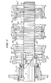
- Figure 2 is an enlarged partial front view of the apparatus of Figure 1 showing the dies in section and also illustrating the apertured tube support guide which projects within the first die,
- Figure 3 is an end view taken on line 3-3 of Figure 1, and
- Figure 4 is a sectional view taken on line 4-4 of Figure 2.
- Referring to Figure 1, the annular corrugating apparatus is indicated generally at 10 and shows a tube 11 inserted in the apparatus prior to the initiation of a corrugating operation. The
apparatus 10 has ahorizontal support base 12 carried by legs 12', a fixed frontvertical support plate 13, movablefront support plates 13', 13", and a plurality of axiallytransverse support plates Tube support bearings non-rotating guide 28 extends outwardly from the housing of thebearing 22 and will be described in more detail in connection with Figure 2. Positioned between thebearings first die block 30 and asecond die block 32. The second stage comprises athird die block 34 and afourth die block 36, while the third stage comprises afifth die block 38 and asixth die block 40. The number of die blocks provided can vary depending upon the diameter and range of tube sizes to be produced with the apparatus. However, we have found that three stages work satisfactorily. Each die block non-rotatably supports an annular die 30' to 40' formed on its inner surface with corrugatinghelical ribs 30" to 40", respectively. - Power to drive the die blocks 30-40 is provided by a motor (not shown) which drives a
small sprocket wheel 42 through a speed reducingdrive mechanism 44. Achain 46 then drives alarge sprocket wheel 48 which is fixed for rotation with a synchronizingshaft 52 mounted at the top of theapparatus 10. A plurality ofsprocket drive chains 54 connectlarge sprockets 56, carried one by each die block, tosmall sprockets 58 which are mounted by bolts 59 on mountingheads 60 keyed to anidler shaft 52. Eachsmall sprocket 58 has a ball joint mounting (not shown) within its mountinghead 60 and eachhead 60 is non-rotatably keyed to akey slot 61 so it can move axially of theidler shaft 52. Thus, movements of thedrive chains 54, which must take place as the die blocks 30-40 are tilted or moved axially, can be readily accommodated. - ; Each of the die blocks 30-40 is mounted for tilting movement about a
respective tilt shaft 64, and alternate die blocks are mounted for movement toward or away from the tube axis from either thefront support wall 13 or a rear support wall 65 (see Figure 3). Shafts 66 in each die block can move in elongate slots 68 in the front orrear walls helical rib 30"-40" (see Figure 2) of the die in the die box will contact the tube 11 in a plane normal to the axis of tube 11. Since the dies in alternate die blocks, such as the die blocks 38 and 40, will contact the tube on the back and front side, respectively, of theribs 38", 40", the pair of dies which form each stage must be tilted in opposite directions. - The penetration depth of each die
rib 30"-40" into the tubing being corrugated is controlled by a feed device which could be mechanically, pneumatically, or hydraulically activated, but is shown in Figure 3 as a manuallyoperable member 74. Themember 74 rotates but does not move axially to turn a threaded portion 74' thereof which is engaged with an axially movable butnon-rotatable nut member 75. Thenut member 75 is pinned to the respective die block (in the case illustrated in Figure 3, the die block 38) by a pin 75'. Figure 3 also shows the mechanism 52-58 for synchronizing the rotation of the various die boxes. - When the apparatus is being set up to corrugate a particular tube, it is necessary that the corrugations produced by each upstream die be picked up by a lead-in portion of the die rib in a succeeding die. Looking at Figure 2, the corrugations lla should arrive at the die 32' so that they are exactly aligned with the lead-in segment of the
die rib 32". This can be accomplished by slightly rotating the downstream die relative to the upstream die as required. Additional axial adjustment of the die blocks can be obtained by moving thevertical walls 13', 13", 65 relative to thebase 12 and clamping them with clamp angles 95 and bolts 95'. In order to accommodate the in-and-out movement of the die blocks and the tilting of the die blocks, some slack is left in thechains 54. If desired, chain tighteners can be provided in the form of idler sprockets (not shown) which are gravity- or spring-biased into engagement with eachrespective chain 54. - In operation, as seen in Figure 1, the leading end of a tube 11 which is to be corrugated into a metal hose is positioned in an
arcuate feed trough 96 positioned at the upstream end of the apparatus. Thetrough 96 is preferably lined with nylon or other low friction material. The length of the tube 11 which can be corrugated is dependent mainly on the space available to the left of the apparatus, and to a lesser extent on the weight of the tube, the power of the drive motor connected to themechanism 44, and the friction contact surface area existing between the dies and the tube for driving the tube without slippage. Since the tube 11 is not driven upstream of the apparatus but rather is driven by virtue of its contact with the several corrugating dieribs 30"-40", it will be obvious that a means must be provided for initially "threading" or "starting" the apparatus. This "starting" operation requires rotation of the tubing and can be accomplished by use of a startingmechanism 97 which includes areciprocable carriage 98 which supports guide rollers 99 which are free to roll alongguide tubes 100. Themechanism 97 has ahousing 102 within which a rotatable combination bearing and drivecollar member 104 is mounted. Themember 104 is , adapted to be rotated by adownstream sprocket member 106 which is driven by a motor drivendrive shaft 108 having a motor (not shown) controlled by amotor start switch 110. Thecollar member 104 has a plurality of screws 112 which are adapted to be forced into tight engagement with the plain tube 11 adjacent to its downstream end, which preferably has had a plug (not shown) temporarily placed into its end to provide support for the thin wall of the tube. The lead end of the plain tube 11 is passed or "threaded" through theapparatus 10 from thefeed trough 96 to thecollar 104 at a time when all of the dies 30'-40' have been backed out of their operative positions. After the lead end of the tube is engaged by the screws 112 in thecollar 104, the starter motor is engaged to rotate thecollar 104 and thus the tube 11. Themotor drive mechanism 44 is preferably disengaged by a clutch 106 from its connection with the synchronizingdrive shaft 52, so that the shaft will be free to_ rotate when the dies are engaged by the rotating tube. The die 30' in thefirst die block 30 is then brought into full engagement with the tube after the tube surface has been contacted by the die 32' in thesecond die block 32. This frictional engagement between the rotating tube and the dies in the first pair of die blocks will initiate rotation of the synchronizingshaft 52 and thus of all the other die blocks 34-40. As the first stage die 30' engages the tube, it is frictionally rotated by the tube and produces the shallow corrugations lla (see Figure 2). This action causes the tube to be helically advanced and forces thetube starting mechanism 97 to roll to the right along thetubes 100. When the first corrugations lla have been advanced to a point that they underlie thehelical rib 32" of the second die 32', that die rib is advanced radially into full engagement with the tube to produce the slightly deeper and more closely pitched corrugations 11b. As corrugations lib reach thedie rib 34" of the die 34', that die is brought into full engagement to produce the corrugations lie. Similarly, the dies 36', 38' and 40' are brought into engagement as they are reached by the corrugations 11c, lid and lle, respectively. Since the respective die ribs only contact one side of the tube, it is necessary to bring the second die of each of the three stages into touching contact with the other side of the tube before the opposed side of the first die of that stage is brought into full engagement with the tube. This contact provides the necessary support for the tube in each stage which would otherwise bend in its passage through the different stages. - By the time the tube has been engaged by the last die 40', it is in firm frictional engagement with all the dies and can be released from the
tube starting mechanism 97 by unscrewing the locking screws 112 in thecollar 104 and removing the back-up plug (not shown). The clutch 106 is then adjusted to lock thesprocket 48 to theshaft 52 and thedrive mechanism 44 is started to cause all the die blocks to be positively driven. When the upstream end of the tube 11 is about to enter thefirst bearing guide 22, it is preferable that thedrive mechanism 44 be stopped, so that the leading end of the next length of tube to be corrugated can be attached to the trailing end of the tube 11. This can easily be done with silver solder, for example, after crimping the end of the new tube to fit it inside the tube 11. In this manner, the corrugations on successive tubes can be formed without having to "re-thread" the machine, and with a loss of only a few inches of tube length in the region of the solder connection. Alternatively, the tube 11 can be corrugated until its trailing end leaves the apparatus, and a new tube can be subjected to the "starting" operation as hereinbefore described. The latter method results in a loss of a few metres of tube between the leading end and the first complete corrugation. - A very critical portion of the apparatus is the
non-rotatable guide 28 which, as best seen in Figure 2, extends through the central opening of the first die 30' in close bearing relationship with the outer wall of the incoming tube 11. Theguide 28 is mounted bybolts 120 to thebearing 22 in which arotatable bearing sleeve 122 is mounted. Theguide 28 has awindow 126 formed in its back wall intermediate its ends as seen in Figure 2. Thiswindow 126 permits access by thedie rib 30" to the tube 11 so it can produce the initial corrugations 11a. The window is preferably as small as possible so that the inside surface of theguide 28 will extend around substantially more than 180° of the circumference of the tube 11 as it is being compressed by thedie rib 30". Preferably, the internal diameter of theguide 28 is between about 0.75 mm to 2.0 mm greater than the external diameter of the tube 11. Thus, the forces exerted on the side of the tube by thedie rib 30" will be transferred by the tube to the wall of theguide 28, especially to the upper and lower portions of the wall. The rigid cylindrical restraint provided by theguide 28 prevents collapse of the tube 11 due to the corrugating forces. This is an extremely important advantage when the tube is of such a large diameter and/or such a small wall thickness that it is incapable of withstanding the corrugating forces without such support. For example, a tube having a wall thickness of 0.30 mm and a diameter of 50 mm, or a tube having a wall thickness of 0.41 mm and a diameter of 100 mm can easily be corrugated with the use of theguide 28. Without theguide 28, the minimum possible wall thickness for a 50 mm tube appears to be about 0.51 mm when using an apparatus of the type disclosed in EP-A-0051454 or about 0.41 mm when using the external inward-forming type of apparatus. - Another important feature of the described embodiment of apparatus according to the invention is the provision of a lead-in portion 130-136 for each of the dies 32'-38' respectively, which preferably has the same pitch as the
principal rib portions 30"-36" of the preceding die. Each lead-in portion 130-136 is preferably formed as an insert in the respective die block which blend smoothly into the principal rib portions of the immediately following die. By providing the lead-in portions with the same pitch as the preceding die, any problem of a succeeding die engaging the side of an incoming corrugation is eliminated. Furthermore, the lead-in portions, which must extend for at least one revolution, cause the compression provided by the respective die to be initiated smoothly and gradually. No lead-in portion is shown for the last die 40' since by this stage of the corrugating operation, the corrugations are deep enough for accurate location of the last die and there is very little decrease in the pitch between the dies 38' and 40'. Although the lead-in portions 130-136 are shown as inserts which have a completely different pitch than the ribs of the dies with which they are associated, the dies could each be machined with a pitch which gradually varies from one end to the other. The aforementioned lead-in portions 130-136 are particularly important when high corrugations are being produced, since the thread pitch in the first die then has to be quite large in order to provide sufficient material for such deep corrugations. The most critical need for a lead-in portion is with respect to the second and third dies where the largest pitch changes take place from die to die. Depending upon the tube size and the pitch and depth of the corrugations being produced, it is sometimes possible to dispense with lead-in portions on two or more of the dies at the downstream end of the tube, thus saving considerable tooling expense. Furthermore, when low corrugation tubing is being produced, it is sometimes possible to eliminate the use of lead-in portions completely when the pitch change between dies is quite small. - The apparatus described is able to produce corrugations on materials such as stainless steel, bronze and carbon steel which are commonly corrugated to form metal hose. In all instances, thinner wall material can be used than has been used in prior art equipment. A single corrugation is produced for every revolution of one of the dies 30'-40' so it is important that each die has at least one complete revolution of its die rib at full depth. It is also important that the dies have tapered entrance and exit portions which can smoothly ease the die ribs into and out of the corrugations. The taper from the internal diameter of the die to the full thread depth preferably takes place over about 90° for the first die and about 45° for the remaining dies, with the exit taper taking place over about 15-30°. The dies preferably have an internal diameter about two to three times the internal diameter of the hose produced.
Claims (11)
Applications Claiming Priority (2)
| Application Number | Priority Date | Filing Date | Title |
|---|---|---|---|
| US06/297,907 US4406142A (en) | 1981-08-31 | 1981-08-31 | Annular corrugator |
| US297907 | 1981-08-31 |
Publications (2)
| Publication Number | Publication Date |
|---|---|
| EP0073652A2 true EP0073652A2 (en) | 1983-03-09 |
| EP0073652A3 EP0073652A3 (en) | 1983-10-12 |
Family
ID=23148216
Family Applications (1)
| Application Number | Title | Priority Date | Filing Date |
|---|---|---|---|
| EP82304497A Withdrawn EP0073652A3 (en) | 1981-08-31 | 1982-08-26 | Annular corrugator |
Country Status (4)
| Country | Link |
|---|---|
| US (1) | US4406142A (en) |
| EP (1) | EP0073652A3 (en) |
| JP (1) | JPS5838321U (en) |
| BR (1) | BR8205077A (en) |
Families Citing this family (5)
| Publication number | Priority date | Publication date | Assignee | Title |
|---|---|---|---|---|
| JPH0267808U (en) * | 1988-11-10 | 1990-05-23 | ||
| DK1084774T3 (en) * | 2000-01-28 | 2003-04-22 | Nexans | Process for Continuously Manufacturing Long-Seam Welded and Corrugated Metal Pipes and Device for Implementing the Process |
| DE10139898C2 (en) * | 2001-08-14 | 2003-10-16 | Kirchner Fraenk Rohr | Corrugated plastic pipe with thread and method for producing a corrugated plastic pipe with thread |
| US7055553B2 (en) * | 2003-02-27 | 2006-06-06 | Titeflex Corporation | Laminated hose construction having one or more intermediate metal barrier layers |
| US9550649B2 (en) * | 2013-05-30 | 2017-01-24 | Stoneage, Inc. | Apparatus for propelling a coil clad hose |
Citations (5)
| Publication number | Priority date | Publication date | Assignee | Title |
|---|---|---|---|---|
| US3353389A (en) * | 1964-04-10 | 1967-11-21 | Calumet & Hecla | Apparatus for use in corrugating metal hose |
| DE1900953A1 (en) * | 1968-01-09 | 1970-02-19 | Pirelli General Cable Works | Method and device for waves of cable sheaths or the like. |
| US3750444A (en) * | 1970-10-29 | 1973-08-07 | Kabel Metallwerke Ghh | Method of continuous production of tubing with helical or annular ribs |
| US3918285A (en) * | 1967-06-21 | 1975-11-11 | Tuyaux Metalliques Flexibles S | Method and apparatus for forming flexible corrugated members |
| US4339936A (en) * | 1980-11-03 | 1982-07-20 | Uop Inc. | Annular corrugator |
Family Cites Families (5)
| Publication number | Priority date | Publication date | Assignee | Title |
|---|---|---|---|---|
| US3128821A (en) * | 1964-04-14 | Corrugator for metal tubing | ||
| US2429491A (en) * | 1944-10-02 | 1947-10-21 | Calumet And Heela Cons Copper | Apparatus for forming annular fins on tubing |
| US3387477A (en) * | 1965-11-29 | 1968-06-11 | Price Pfister Brass Mfg | Apparatus and method for roll forming flexible tubing |
| DE1916357A1 (en) * | 1969-03-29 | 1971-06-16 | Kabel Metallwerke Ghh | Device for the continuous production of tubes with annular shape corrugation |
| DE2804990C2 (en) * | 1978-02-06 | 1985-08-29 | kabelmetal electro GmbH, 3000 Hannover | Device for the continuous corrugation of thin-walled pipes |
-
1981
- 1981-08-31 US US06/297,907 patent/US4406142A/en not_active Expired - Fee Related
-
1982
- 1982-08-26 EP EP82304497A patent/EP0073652A3/en not_active Withdrawn
- 1982-08-30 BR BR8205077A patent/BR8205077A/en unknown
- 1982-08-31 JP JP1982132237U patent/JPS5838321U/en active Pending
Patent Citations (5)
| Publication number | Priority date | Publication date | Assignee | Title |
|---|---|---|---|---|
| US3353389A (en) * | 1964-04-10 | 1967-11-21 | Calumet & Hecla | Apparatus for use in corrugating metal hose |
| US3918285A (en) * | 1967-06-21 | 1975-11-11 | Tuyaux Metalliques Flexibles S | Method and apparatus for forming flexible corrugated members |
| DE1900953A1 (en) * | 1968-01-09 | 1970-02-19 | Pirelli General Cable Works | Method and device for waves of cable sheaths or the like. |
| US3750444A (en) * | 1970-10-29 | 1973-08-07 | Kabel Metallwerke Ghh | Method of continuous production of tubing with helical or annular ribs |
| US4339936A (en) * | 1980-11-03 | 1982-07-20 | Uop Inc. | Annular corrugator |
Also Published As
| Publication number | Publication date |
|---|---|
| JPS5838321U (en) | 1983-03-12 |
| US4406142A (en) | 1983-09-27 |
| BR8205077A (en) | 1983-08-09 |
| EP0073652A3 (en) | 1983-10-12 |
Similar Documents
| Publication | Publication Date | Title |
|---|---|---|
| US3407638A (en) | Method for forming serrated or corrugated hollow tubes | |
| KR100785857B1 (en) | Method and apparatus of manufacturing grooved pipe, and structure thereof | |
| US6488079B2 (en) | Corrugated heat exchanger element having grooved inner and outer surfaces | |
| US3327512A (en) | Fine pitch finned tubing and method of producing the same | |
| US4819469A (en) | Method for rolling tapered threads on bars | |
| US4090382A (en) | Expanding and beading apparatus for tubes and the like | |
| CA2103413C (en) | Self-tracking roll for grooving malleable pipe | |
| EP0073652A2 (en) | Annular corrugator | |
| US3881340A (en) | Drawing machine | |
| US4339936A (en) | Annular corrugator | |
| EP0907433B1 (en) | Method for roll forming and machine and blank for this | |
| JPS5912365B2 (en) | Internally grooved metal tube processing method | |
| US2865424A (en) | Machine for forming finned heat transfer tubes | |
| US4435968A (en) | Apparatus for corrugating pipes | |
| US3855832A (en) | Method of and apparatus for manufacturing integral finned tubing | |
| US5003690A (en) | Finning and thread rolling machine | |
| US3260088A (en) | Apparatus for corrugating metal tubing | |
| US3543551A (en) | Apparatus for helically corrugating metal tubing | |
| US3260090A (en) | Method and apparatus for reducing tubing | |
| JP3345225B2 (en) | Manufacturing method of deformed pipe | |
| US1492067A (en) | Apparatus for making tubes | |
| JP4628858B2 (en) | Double tube manufacturing method and apparatus | |
| US2693779A (en) | Machine for making round flexible metal tubes | |
| US4596127A (en) | Method and machine for splining clutch hubs | |
| US3580024A (en) | Method and apparatus for corrugating tubes |
Legal Events
| Date | Code | Title | Description |
|---|---|---|---|
| PUAI | Public reference made under article 153(3) epc to a published international application that has entered the european phase |
Free format text: ORIGINAL CODE: 0009012 |
|
| AK | Designated contracting states |
Designated state(s): AT BE CH DE FR GB IT LI LU NL SE |
|
| PUAL | Search report despatched |
Free format text: ORIGINAL CODE: 0009013 |
|
| AK | Designated contracting states |
Designated state(s): AT BE CH DE FR GB IT LI LU NL SE |
|
| 17P | Request for examination filed |
Effective date: 19840308 |
|
| STAA | Information on the status of an ep patent application or granted ep patent |
Free format text: STATUS: THE APPLICATION IS DEEMED TO BE WITHDRAWN |
|
| 18D | Application deemed to be withdrawn |
Effective date: 19850806 |
|
| RIN1 | Information on inventor provided before grant (corrected) |
Inventor name: WODRICH, LESTER HENRY Inventor name: KELSTROM, DONALD GORDON Inventor name: WILLIAMS, JOHN DAVID |