EP0073518A2 - Steuereinrichtung für die Zahl der wirkenden Zylinder eines Dieselmotors - Google Patents
Steuereinrichtung für die Zahl der wirkenden Zylinder eines Dieselmotors Download PDFInfo
- Publication number
- EP0073518A2 EP0073518A2 EP82108006A EP82108006A EP0073518A2 EP 0073518 A2 EP0073518 A2 EP 0073518A2 EP 82108006 A EP82108006 A EP 82108006A EP 82108006 A EP82108006 A EP 82108006A EP 0073518 A2 EP0073518 A2 EP 0073518A2
- Authority
- EP
- European Patent Office
- Prior art keywords
- cylinders
- fuel
- circuit
- pulses
- engine
- Prior art date
- Legal status (The legal status is an assumption and is not a legal conclusion. Google has not performed a legal analysis and makes no representation as to the accuracy of the status listed.)
- Granted
Links
Images


Classifications
-
- F—MECHANICAL ENGINEERING; LIGHTING; HEATING; WEAPONS; BLASTING
- F02—COMBUSTION ENGINES; HOT-GAS OR COMBUSTION-PRODUCT ENGINE PLANTS
- F02D—CONTROLLING COMBUSTION ENGINES
- F02D41/00—Electrical control of supply of combustible mixture or its constituents
- F02D41/30—Controlling fuel injection
- F02D41/38—Controlling fuel injection of the high pressure type
- F02D41/40—Controlling fuel injection of the high pressure type with means for controlling injection timing or duration
-
- F—MECHANICAL ENGINEERING; LIGHTING; HEATING; WEAPONS; BLASTING
- F02—COMBUSTION ENGINES; HOT-GAS OR COMBUSTION-PRODUCT ENGINE PLANTS
- F02D—CONTROLLING COMBUSTION ENGINES
- F02D41/00—Electrical control of supply of combustible mixture or its constituents
- F02D41/008—Controlling each cylinder individually
- F02D41/0087—Selective cylinder activation, i.e. partial cylinder operation
-
- F—MECHANICAL ENGINEERING; LIGHTING; HEATING; WEAPONS; BLASTING
- F02—COMBUSTION ENGINES; HOT-GAS OR COMBUSTION-PRODUCT ENGINE PLANTS
- F02B—INTERNAL-COMBUSTION PISTON ENGINES; COMBUSTION ENGINES IN GENERAL
- F02B3/00—Engines characterised by air compression and subsequent fuel addition
- F02B3/06—Engines characterised by air compression and subsequent fuel addition with compression ignition
-
- Y—GENERAL TAGGING OF NEW TECHNOLOGICAL DEVELOPMENTS; GENERAL TAGGING OF CROSS-SECTIONAL TECHNOLOGIES SPANNING OVER SEVERAL SECTIONS OF THE IPC; TECHNICAL SUBJECTS COVERED BY FORMER USPC CROSS-REFERENCE ART COLLECTIONS [XRACs] AND DIGESTS
- Y02—TECHNOLOGIES OR APPLICATIONS FOR MITIGATION OR ADAPTATION AGAINST CLIMATE CHANGE
- Y02T—CLIMATE CHANGE MITIGATION TECHNOLOGIES RELATED TO TRANSPORTATION
- Y02T10/00—Road transport of goods or passengers
- Y02T10/10—Internal combustion engine [ICE] based vehicles
- Y02T10/40—Engine management systems
Definitions
- the present invention relates to an apparatus for controlling the injection of fuel into a Diesel engine and more particularly to an apparatus for controlling the number of operative cylinders of a Diesel engine.
- a control apparatus comprising a fuel injection pump whose injection quantity is determined in accordance with the open duration of an electromagnetic valve, a control circuit for detecting the operating conditions of a Diesel engine to determine the number of cylinders to be operated, a register for storing the cylinder control data from the control circuit, and a pulse generating circuit responsive to cylinder pulses synchronized with the shaft rotation of the Diesel engine and the stored value of the register to control the application of valve opening pulses to the electromagnetic valve, whereby the number of the Diesel engine cylinders to be operated is controlled in accordance with the engine operating conditions.
- the desired control is effected efficiently in accordance with the engine operating conditions.
- the control apparatus comprises a microprocessor MPU 100, a read-only memory ROM 102, a random-access memory RAM 104, an input/output circuit 106 (e.g., the Hitachi HD 46506), sensors 108 and 110 and a fuel injection pump 112.
- the input/output circuit 106 comprises an analog-to-digital converter 114, an engine speed detecting circuit 116, a cylinder control circuit 122, an INT pulse generating circuit 120 and a fuel injection pulse generating circuit 118.
- the sensor 108 is comprised for example of a potentiometer which generates an analog voltage VA corresponding to an accelerator position.
- the analog voltage VA is converted to a digital signal 9AC by the A-D converter 114, taken by the microprocessor 100 and stored in the RAM 104.
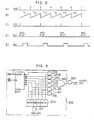
- the injection pump 112 includes the crank angle sensor 110 for generating cylinder cycle indicative pulses REF in synchronism with the rotation of the engine shaft and the pulses shown in (A) of Fig. 2 are generated in correspondence to the Nos. 1 to 6 cylinders.
- the pulses REF are applied to the engine speed detecting circuit 116.
- the circuit 116 counts clocks by a counter so that the periods T 1 to T 6 of the respective cylinder pulses are detected and the period T is applied to the microprocessor MPU 100.
- the period T is the reciprocal of the engine speed and the MPU 100 computes an engine speed N from the period T and stores it in the RAM 104.
- the MPU 100 computes the desired fuel supply quantity and cylinder control data in accordance with the various programs stored in the ROM 102 and the results are respectively set in the fuel injection pulse generating circuit 118 and the cylinder control circuit 122. Also, a constant value INTL is set in the INT pulse generating circuit 120.
- the RAM 104 is used for storing the working data required for the said computations.
- the transmission of the various data between the MPU 100, the ROM 102, the RAM 104 and the input/output circuit 106 is effected through a bus 130 including a data bus and an address bus.
- Fig. 2 is a timing chart for explaining the operation of the blocks in Fig. 1 and the cylinder control circuit 122 is responsive to the pulse REF shown in (A) to generate the pulse CYL shown in (C).
- the pulse CYL is generated in response to the pulse REF in (A) and which of the REF pulses 1 to 6 corresponds to the CYL pulse is determined in accordance with the cylinder control data set in the cylinder control circuit 122.
- the CYL pulses are generated in correspondence to the REF pulses 1, 3 and 5. This means that only the three cylinders of the six-cylinder engine, i.e., the Nos. 1, 3 and 5 cylinders are used to operate the engine and the operation of the remaining Nos.
- the CYL pulse is applied to the INT pulse generating circuit 120 thereby generating a pulse INT which is shifted from the CYL pulse by a given amount INTL.
- This INT pulse is applied as a trigger pulse to the INJ pulse generating circuit 118 which in turn generates an INJ pulse for operating a fuel injection valve 124.
- the cylinder control circuit 122 controls the corresponding relation between the R EF pulses and the CYL pulses thereby controlling the number of the operative cylinders of the engine.
- Fig. 3 shows a detailed circuit construction of the cylinder control circuit 122 in Fig. 1.
- the circuit 122 comprises a ring counter 302, a register 304, AND gates 306, 308, 310, 312, 314 and 316, an OR gate 318 and an AND gate 320.
- the REF pulses applied to the ring counter 302 are cylinder pulses so that for a six-cylinder Diesel engine six pulses are generated at intervals of an equal angle for every two revolutions of the engine shaft as shown in (A) of Fig. 2.
- the ring counter 302 counts the REF pulses to generate pulses Q l to Q 6 . Shown in (A) of Fig. 4 are the R EF pulses shown in (A) of Fig.
- the REF pulses 1 to 6 are generated in synchronism with the Nos. 1 to 6 cylinders of the Diesel engine.
- the Q 1 to Q 6 pulses shown respectively in (C) to (H) of Fig. 4 are generated from the ring counter 302 and are applied to the AND gates 306, 308, 310, 312, 314 and 316, respectively.
- Shown in (B) of Fig. 4 is a signal for resetting the ring count 302 and the ring counter 302 is reset by an REF pulse indicative of the No. 1 cylinder.
- the number of shift stages of the ring counter 302 corresponds to the number of engine cylinders so that once the ring counter 302 is reset at the beginning, it operates properly and there is no need to particularly reset it repeatedly.
- the ring counter 302 is reset each time so as to prevent any erroneous operation due to noise.
- the cylinder control data computed by the MPU 100 is applied to the bits R 1 to R 6 of the register 304 through the bus 130.
- the cylinder control data is 101010
- the data 101010 is stored in the bits R 1 to R 6 of the register 304.
- the outputs of the AND gates 306, 308, 310, 312, 314 and 316 are each applied to the AND gate 320 via the OR gate 318 and is ANDed with the REF pulse to generate a pulse.
- the pulses shown in (O) of Fig. 4 are generated from the AND gate 320 and are applied to the INT pulse generating circuit 120 of Fig. 1.
- Fig. 5 is a detailed circuit diagram of the INT pulse generating circuit 120 and the INJ pulse generating circuit 118 of Fig. 1 and Fig. 6 is a waveform diagram for explaining the operation of these circuits.
- the CYL pulse shown in (A) of Fig. 6 is applied to a waveform reshaping circuit 524, the pulse shown in (B) of Fig. 6 is generated and thus a counter 504 and a flip-flop 514 are reset.
- an AND gate 518 comes into operation so that clocks POS are applied to the counter 504 and it counts up.
- the clock POS is a pulse indicative for example of a unit rotational angle of 2° of the engine shaft and it is sent from a crank angle sensor which is not shown.
- the shift value INTL is applied to a register 502 and thus the output of the counter 504 is compared with the data INTL by a comparator 506.
- the flip-flop 514 is set as shown in (D) of Fig. 6 and the pulse shown in (E) of Fig. 6 is generated from a waveform reshaping circuit 522.
- the AND gate 518 is rendered inoperative and the application of clocks POS to the counter 504 is stopped. This has the effect of preventing any erroneous operation due to overflowing of the counter 504.
- the output of the waveform reshaping circuit 522 sets a flip-flop 516 thereby generating the INT pulse shown in (G) of Fig. 6 and also resets a counter 510 as shown in (F) of Fig. 6.
- an AND gate 520 comes into operation so that a clock generated at intervals of a given time is applied to a counter 510 via the AND gate 520.
- the data INJ indicative of the INJ pulse duration is stored in a register 508 and thus the output of the counter 510 is compared with the data INJ by a comparator 512.
- the flip-flop 516 is reset and the pulse INJ is cut off.
- the AND gate 520 comes out of operation and the application of clocks to the counter 510 is stopped. This prevents overflowing of the counter 510.
- the pulse INJ is applied to the injection valve 124 of the injection pump 112.
- Fig. 7 is a vertical sectional view of the fuel injection valve 112 of Fig. 1.
- a rotary distributor 704 which is positioned centrally in the injection pump 112 and coupled to the engine shaft through a shaft 702, is rotatably disposed in a sleeve 708 which is force fit and firmly positioned in a cylinderical body 706.
- a pressure pump Disposed at the lower end of the rotary distributor 704 is a pressure pump comprising a rotor 710, a roller 712 . and an annular cam 760.
- a vane type supply pump 720 is disposed at the upper end of the rotary distributor 704.
- the fuel is supplied from a fuel tank to an inlet port 730 in the upper part of the injection pump and the fuel is supplied to the vane type pump 720 through a passage 734 and a filter 732.
- the fuel from the vane type pump 720 is supplied to a passage 750 and a part of the fuel is returned to a chamber 738 via a passage 736.
- a passage 742 is communicated with the chamber 738 and thus the fuel in the chamber 738 is returned to the fuel tank.
- the rotor 710 is formed with a transverse hole 756 and a pair of plungers 758 are received within the transverse hole 756.
- the pair of plungers 758 are moved through the roller 712 and a roller support 762 by the action of the annular cam 760 disposed in the lower part of the body 706. This compresses the fuel within the fuel passage formed centrally in the rotary distributor 704 and a shuttle 764 is urged upwardly.
- a longitudinal passage 766 formed centrally in the rotary distributor 704 is communicated at its lower end with the transverse hole 756 and the shuttle 764 is slidably disposed in the longitudinal passage 766.
- the amount of movement of the shuttle 764 is regulated by the amount of fuel supplied to the passage 766 through passages 768, 770 and 772 and a pair of upper and lower stoppers 774.
- Fig. 8 is a sectional view taken along the line A-A of Fig. 7.
- the lower stopper 774 is disposed in the center hole of the rotary distributor 704 and the rotary distributor 704 is rotatable within the central hole of the sleeve 708 fixedly positioned in the body 706.
- the body 706 is enclosed by a case 802 and is integral with an electromagnetic valve 806A mounted at the right end of a valve hole 804.
- Numeral 808 designates a valve stem, 810 an outlet passage shown by the broken line, 780 a transverse hole communicated with the outlet passage 810, and 812 a transverse hole communicating a suction space 814 with the passage 780.
- Numeral 820 designates an orifice opposing the valve stem 808 and communication with an injection communication port is provided by way of the orifice 820.
- the fuel supplied from the electromagnetic valve 806A is pressurized by the shuttle 764 of Fig. 7 and is supplied through distribution outlets 792, 794 and 796 to the corresponding cylinders.
- the timing of the pressurization is determined by the amount of fuel supplied from an electromagnetic valve 806B.
- Figs. 9 to 12 are cross-sectional views of the fuel injection valve, and Fig. 9 is a sectional view taken along the line B-B of Fig. 7 showing fuel delivery passages.
- a delivery passage 918 is selectively aligned with a plurality of delivery ports 916 formed in the sleeve 708 and the delivery ports 916 are each connected with a mounting hole of a pressure valve 920 so that the pressurized fuel in a working chamber 922 is distributed and supplied to the six cylinders of the Diesel engine.
- the fuel is supplied to each of the six cylinders for every rotation of the rotary distributor 704.
- Fig. 10 is a sectional view taken along the line C-C of Fig. 7 showing fuel inlet passages.
- This portion of the rotary distributor 704 is formed with six inlet passages 940 which are arranged at intervals of an equal angle and communicated with the working chamber 922.
- the sleeve 708 is formed with a single inlet port 942.
- the inlet port 942 is arranged so that the inlet port 942 is communicated with the inlet passages 940 at least when the delivery passage 918 is not aligning with the delivery ports 916.
- Fig. 11 is a sectional view taken along the line D-D of Fig. 7 showing the shuttle 764 in section and a fuel escape passage 944.
- the outer diameter of the sleeve 708 is reduced to form a fuel sump groove 946 and a plurality of escape ports 948 are arranged at intervals of an equal angle to communicate with the fuel sump groove 946.
- the escape passage 944 communicates with each of the six escape ports 948 for every rotation of the rotary distributor 704 so that the fuel is gathered in the sump groove 946 and any extra fuel is discharged through the transverse hole 780 and the outlet passage 810.
- Fig. 12 is a sectional view taken along the line E-E of Fig. 7 showing a stopper 960 in section.
- This portion of the rotary distributor 704 is formed with the six injection timing adjusting passages 768 arranged at intervals of an equal angle and these passages 768 are successively co-municated with the passage 778.
- the inlet port 942 is aligned with one of the inlet passages 940.
- the electromagnetic valve 806A is operated so that the valve stem 808 is opened and the fuel in the suction space 814 reaches the delivery port 916 through the valve hole 804, the orifice 820 and an injection communication port 962 thereby delivering the injection fuel to the working chamber 922 on the side of the delivery passage 918.
- the fuel delivered into the working chamber 922 moves the shuttle 764 toward the transverse hole 780 and thus the fuel is supplied to each of the engine cylinders from the working chamber 922 through the pressure valves 788 of Fig. 7.
- the shuttle 764 is moved so long as the escape passage 786 is covered by the rear side of the shuttle 764, and when the escape passage 786 is not covered, the shuttle 764 is stopped moving any further and the fuel remaining in the pressure pump chamber 766 flows to the outlet passage 810 thorugh the escape passage 786 and the escape ports 948.
- the rotary distributor 704 is rotating, the above-mentioned cycle is repeated automatically.
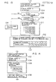
- Fig. 13 is a flow chart for computing a number of cylinders control data which is set in the register 304 of F ig. 3.
- Steps 1002 and 1004 respectively detects an accelerator position eTH and an engine speed N as engine condition indicative parameters.
- a step 1006 determines whether the engine speed N is greater than a given value N 1 so that if it is, the step 1006 transfers to a step 1008 for controlling the number of cylinders.
- the step 1008 determines whether there is a deceleration condition so that it transfers to a step 1010 only when there exists a deceleration condition.
- a transfer is made to a step 1014 for effecting a normal operation control by which all the cylinders are operated.
- the step 1014 selects the number of the cylinders in the engine, i.e., the number 6 in this embodiment and then transfers to a step 1012.
- the step 1010 searches a table showing the numbers of operative cylinders as functions of the engine parameters N and eTH and determines the number of operative cylinders corresponding to the engine operating condition. The table is stored in the ROM 102. If the step 1010 searches the number 0, it means that the fuel supply to all the cylinders is cut off. If the number 4 is searched, it means that the fuel is supplied only to the four of the six cylinders. If the number 6 is searched, it means the ordinary control which supplies the fuel to all the cylinders.
- the step 1012 determines by table searching a control data indicating which of the six cylinders are to be operated and sets the same in the register304.
- the corresponding control data is 000000
- the control data corresponding to the numbers 3 and 6 are respectively 101010 and 111111.
- Fig. 14 is a flow chart for computing a data INJ which is set in the register 508.
- Steps 1102 and 1104 respectively detect an accelerator position eTH and an engine speed N as engine parameters, and a step 1106 determines the desired fuel injection quantity INJ in accordance with the detected parameters N and 9TH.
- the fuel injection quantity INJ is represented as functions of the parameters N and 9TH and such fuel injection quantities INJ are stored in the form of a table in the R OM 102.
- the desired fuel injection quantity INJ is searched in accordance with the table.
- the searched fuel injection quantity INJ is set in the INJ register 508 by a step 1108.
- a pulse corresponding to the computed quantity INJ is supplied to the fuel injection valve 124 and the fuel is supplied to the corresponding cylinders through the fuel injection pump 112.
- FIG. 1 The broken line circuits in Fig. 1 show the principal part of another embodiment of the invention.
- This embodiment is so constructed that in Fig. 1 the output of the crank angle sensor 110 is applied directly to the INT pulse generating circuit 120 as shown by the broken line and the output of the INJ pulse generating circuit 118 is applied to the injection valve 124 not directly but through an AND gate 140 as shown by the broken lines.
- one input of the AND gate 140 receives the INJ pulse as mentioned previously and the other input receives the output of a cylinder control circuit 300.
- all the REF pulses are applied to the INT pulse generating circuit 120 and thus the INJ pulse generating circuit 118 generates the INJ pulse corresponding to all the REF pulses.
- the OR gate 318 generates an output only in response to each of the REF pulses 1, 3 and 5 shown in (I), (K) and (M) of Fig. 4 and only the INJ pulses corresponding to the Nos. 1, 3 and 5 cylinders are applied to the injection valve 124 through the AND gate 140. Consequently, exactly the same effects as the first embodiment are obtained.
Landscapes
- Engineering & Computer Science (AREA)
- Chemical & Material Sciences (AREA)
- Combustion & Propulsion (AREA)
- Mechanical Engineering (AREA)
- General Engineering & Computer Science (AREA)
- Electrical Control Of Air Or Fuel Supplied To Internal-Combustion Engine (AREA)
- Combined Controls Of Internal Combustion Engines (AREA)
- Fuel-Injection Apparatus (AREA)
- Output Control And Ontrol Of Special Type Engine (AREA)
Applications Claiming Priority (2)
| Application Number | Priority Date | Filing Date | Title |
|---|---|---|---|
| JP56138845A JPS5841232A (ja) | 1981-09-02 | 1981-09-02 | 気筒数変換形燃料噴射ポンプの制御装置 |
| JP138845/81 | 1981-09-02 |
Publications (3)
| Publication Number | Publication Date |
|---|---|
| EP0073518A2 true EP0073518A2 (de) | 1983-03-09 |
| EP0073518A3 EP0073518A3 (en) | 1985-10-30 |
| EP0073518B1 EP0073518B1 (de) | 1990-01-17 |
Family
ID=15231522
Family Applications (1)
| Application Number | Title | Priority Date | Filing Date |
|---|---|---|---|
| EP82108006A Expired - Lifetime EP0073518B1 (de) | 1981-09-02 | 1982-08-31 | Steuereinrichtung für die Zahl der wirkenden Zylinder eines Dieselmotors |
Country Status (4)
| Country | Link |
|---|---|
| US (1) | US4552114A (de) |
| EP (1) | EP0073518B1 (de) |
| JP (1) | JPS5841232A (de) |
| DE (1) | DE3280089D1 (de) |
Cited By (1)
| Publication number | Priority date | Publication date | Assignee | Title |
|---|---|---|---|---|
| FR2571782A1 (fr) * | 1984-10-13 | 1986-04-18 | Lucas Ind Plc | Systeme de commande de distribution de combustible pour moteur a combustion interne a allumage par compression |
Families Citing this family (23)
| Publication number | Priority date | Publication date | Assignee | Title |
|---|---|---|---|---|
| US5040507A (en) * | 1990-03-07 | 1991-08-20 | Cummins Engine Company, Inc. | Method and device for variable idle speed control of an internal combustion engine |
| US5042444A (en) * | 1990-03-07 | 1991-08-27 | Cummins Engine Company, Inc. | Device and method for altering the acoustic signature of an internal combustion engine |
| US5119781A (en) * | 1991-02-28 | 1992-06-09 | General Motors Corporation | Control of engine fuel injection during transitional periods associated with deceleration fuel cut-off |
| JP3601837B2 (ja) * | 1992-11-16 | 2004-12-15 | 三菱自動車工業株式会社 | 休筒機構付きエンジンの燃料制御装置 |
| US5408974A (en) * | 1993-12-23 | 1995-04-25 | Ford Motor Company | Cylinder mode selection system for variable displacement internal combustion engine |
| US5408966A (en) * | 1993-12-23 | 1995-04-25 | Ford Motor Company | System and method for synchronously activating cylinders within a variable displacement engine |
| US5374224A (en) * | 1993-12-23 | 1994-12-20 | Ford Motor Company | System and method for controlling the transient torque output of a variable displacement internal combustion engine |
| US5431139A (en) * | 1993-12-23 | 1995-07-11 | Ford Motor Company | Air induction control system for variable displacement internal combustion engine |
| US5398544A (en) * | 1993-12-23 | 1995-03-21 | Ford Motor Company | Method and system for determining cylinder air charge for variable displacement internal combustion engine |
| US5490486A (en) * | 1994-10-05 | 1996-02-13 | Ford Motor Company | Eight cylinder internal combustion engine with variable displacement |
| US6009857A (en) * | 1997-05-29 | 2000-01-04 | Caterpillar Inc. | Compression ignition cylinder cutout system for reducing white smoke |
| US5826563A (en) * | 1997-07-28 | 1998-10-27 | General Electric Company | Diesel engine cylinder skip firing system |
| US6405705B1 (en) * | 2000-05-19 | 2002-06-18 | General Electric Company | Method and apparatus for reducing locomotive diesel engine smoke using skip firing |
| EP1225321A3 (de) * | 2001-01-19 | 2003-05-02 | Jenbacher Aktiengesellschaft | Mehrzylindrige stationäre Brennkraftmaschine |
| US6892701B2 (en) * | 2003-01-28 | 2005-05-17 | General Electric Company | Method and apparatus for controlling locomotive smoke emissions during transient operation |
| US8646435B2 (en) * | 2008-07-11 | 2014-02-11 | Tula Technology, Inc. | System and methods for stoichiometric compression ignition engine control |
| RU2468230C1 (ru) * | 2011-04-13 | 2012-11-27 | Рустам Рифович Галиуллин | Способ регулирования частоты вращения дизель-электрического силового агрегата |
| RU2543105C2 (ru) * | 2013-04-23 | 2015-02-27 | Рустам Рифович Галиуллин | Способ повышения эффективного кпд дизеля электрического силового агрегата |
| KR101509958B1 (ko) * | 2013-10-30 | 2015-04-08 | 현대자동차주식회사 | 인젝터 특성 보정 장치 |
| US11053828B2 (en) | 2015-11-11 | 2021-07-06 | Tula Technology, Inc. | Separately determining firing density and pumping density during firing density transitions for a lean-burn internal combustion engine |
| US10823029B2 (en) | 2015-11-11 | 2020-11-03 | Tula Technology, Inc. | Determining firing density of a skip fire controlled lean-burn engine using air-fuel ratio and exhaust temperatures |
| US11560818B2 (en) | 2015-11-11 | 2023-01-24 | Tula Technology, Inc. | Lean burn internal combustion engine exhaust gas control |
| WO2017083389A1 (en) | 2015-11-11 | 2017-05-18 | Tula Technology, Inc. | Clean burn internal combustion engine exhaust gas temperature control |
Family Cites Families (15)
| Publication number | Priority date | Publication date | Assignee | Title |
|---|---|---|---|---|
| US2875742A (en) * | 1956-09-10 | 1959-03-03 | Gen Motors Corp | Economy engine and method of operation |
| US3703888A (en) * | 1969-12-01 | 1972-11-28 | Bosch Gmbh Robert | Device for the fuel quantity control in response to operational variables of an internal combustion engine |
| JPS4898221A (de) * | 1972-03-30 | 1973-12-13 | ||
| US3996915A (en) * | 1973-11-05 | 1976-12-14 | Resonance Motors, Inc. | Engine selectively utilizing hybrid thermodynamic combustion cycles |
| US4040395A (en) * | 1973-11-05 | 1977-08-09 | Demetrescu Mihai C | Engine selectively utilizing hybrid thermodynamic combustion cycles |
| JPS52107438A (en) * | 1976-03-08 | 1977-09-09 | Nissan Motor Co Ltd | Fuel supply cylinder number control engine |
| DE2632319A1 (de) * | 1976-07-17 | 1978-01-26 | Bosch Gmbh Robert | Verfahren und vorrichtung zur steuerung der zusammensetzung des einer brennkraftmaschine zugefuehrten betriebsgemisches |
| IT1124715B (it) * | 1976-09-06 | 1986-05-14 | Alfa Romeo Spa | Impianto di iniezione intermittente di combustibile per motori a scoppio |
| US4103655A (en) * | 1977-03-22 | 1978-08-01 | Donald Kennedy Coles | Internal combustion engine |
| US4172434A (en) * | 1978-01-06 | 1979-10-30 | Coles Donald K | Internal combustion engine |
| JPS6024312B2 (ja) * | 1978-01-12 | 1985-06-12 | 日産自動車株式会社 | デイ−ゼルエンジンの予熱栓加熱装置 |
| JPS5817339B2 (ja) * | 1978-05-12 | 1983-04-06 | 日産自動車株式会社 | 燃料遮断装置 |
| JPS54148928A (en) * | 1978-05-12 | 1979-11-21 | Nissan Motor Co Ltd | Fuel shut-off device |
| DE2942851A1 (de) * | 1979-10-24 | 1981-05-07 | Vdo Adolf Schindling Ag, 6000 Frankfurt | Einrichtung zum abschalten mindestens eines zylinders einer mehrzylinder-brennkraftmaschine |
| DE3013052A1 (de) * | 1980-04-03 | 1981-10-15 | Robert Bosch Gmbh, 7000 Stuttgart | Zuend- und kraftstoffeinspritzanlage fuer mehrzylindrige brennkraftmaschinen |
-
1981
- 1981-09-02 JP JP56138845A patent/JPS5841232A/ja active Pending
-
1982
- 1982-08-31 EP EP82108006A patent/EP0073518B1/de not_active Expired - Lifetime
- 1982-08-31 DE DE8282108006T patent/DE3280089D1/de not_active Expired - Lifetime
-
1984
- 1984-12-24 US US06/685,258 patent/US4552114A/en not_active Expired - Fee Related
Cited By (1)
| Publication number | Priority date | Publication date | Assignee | Title |
|---|---|---|---|---|
| FR2571782A1 (fr) * | 1984-10-13 | 1986-04-18 | Lucas Ind Plc | Systeme de commande de distribution de combustible pour moteur a combustion interne a allumage par compression |
Also Published As
| Publication number | Publication date |
|---|---|
| EP0073518A3 (en) | 1985-10-30 |
| EP0073518B1 (de) | 1990-01-17 |
| JPS5841232A (ja) | 1983-03-10 |
| US4552114A (en) | 1985-11-12 |
| DE3280089D1 (de) | 1990-02-22 |
Similar Documents
| Publication | Publication Date | Title |
|---|---|---|
| EP0073518A2 (de) | Steuereinrichtung für die Zahl der wirkenden Zylinder eines Dieselmotors | |
| US4545345A (en) | Air/fuel induction system for a multi-cylinder internal combustion engine | |
| US4790277A (en) | Self-adjusting fuel injection system | |
| CA1193161A (en) | Diesel fuel injection pump with adaptive torque balance control | |
| US5642714A (en) | Fuel system | |
| US4022165A (en) | Fuel injection system for successively introducing multiple fuel quantities in an engine cylinder | |
| US5103792A (en) | Processor based fuel injection control system | |
| US4200063A (en) | Engine fuel injection control apparatus with simultaneous pulse width and frequency adjustment | |
| JPS60125756A (ja) | 分配型燃料噴射ポンプ | |
| US4398519A (en) | Fuel injection apparatus for internal combustion engines, in particular for diesel engines | |
| GB1482548A (en) | Fuel injection pumps for internal combustion engines | |
| US4509487A (en) | Fuel system for multi-cylinder engine | |
| GB2076078A (en) | A fuel injection pump | |
| US4767288A (en) | Fuel injection pump | |
| US3404668A (en) | Fuel injection pump | |
| US4446836A (en) | Fuel injection pumping apparatus | |
| US4662336A (en) | Fuel injection pump for self-igniting internal combustion engines | |
| US5005548A (en) | Fuel injection pump | |
| US3409226A (en) | Fuel injection apparatus for piston-type internal combustion engines | |
| GB2058947A (en) | Fuel pumping apparatus | |
| US3101079A (en) | Liquid fuel pumps for internal combustion engines | |
| US4463726A (en) | Distributor pump for injecting fuel into internal combustion engines | |
| DE3069719D1 (en) | Fuel-injection device for internal combustion engines, especially for diesel engines | |
| GB2183061A (en) | A fuel injection device for internal combustion engines | |
| US4132205A (en) | Metering valve for fuel injection |
Legal Events
| Date | Code | Title | Description |
|---|---|---|---|
| PUAI | Public reference made under article 153(3) epc to a published international application that has entered the european phase |
Free format text: ORIGINAL CODE: 0009012 |
|
| AK | Designated contracting states |
Designated state(s): CH DE FR GB IT LI NL SE |
|
| PUAL | Search report despatched |
Free format text: ORIGINAL CODE: 0009013 |
|
| AK | Designated contracting states |
Designated state(s): CH DE FR GB IT LI NL SE |
|
| 17P | Request for examination filed |
Effective date: 19851104 |
|
| 17Q | First examination report despatched |
Effective date: 19860918 |
|
| R17C | First examination report despatched (corrected) |
Effective date: 19870706 |
|
| GRAA | (expected) grant |
Free format text: ORIGINAL CODE: 0009210 |
|
| AK | Designated contracting states |
Kind code of ref document: B1 Designated state(s): DE FR GB |
|
| REF | Corresponds to: |
Ref document number: 3280089 Country of ref document: DE Date of ref document: 19900222 |
|
| ET | Fr: translation filed | ||
| PLBE | No opposition filed within time limit |
Free format text: ORIGINAL CODE: 0009261 |
|
| STAA | Information on the status of an ep patent application or granted ep patent |
Free format text: STATUS: NO OPPOSITION FILED WITHIN TIME LIMIT |
|
| 26N | No opposition filed | ||
| PGFP | Annual fee paid to national office [announced via postgrant information from national office to epo] |
Ref country code: FR Payment date: 19920630 Year of fee payment: 11 |
|
| PGFP | Annual fee paid to national office [announced via postgrant information from national office to epo] |
Ref country code: GB Payment date: 19920821 Year of fee payment: 11 |
|
| PGFP | Annual fee paid to national office [announced via postgrant information from national office to epo] |
Ref country code: DE Payment date: 19921026 Year of fee payment: 11 |
|
| PG25 | Lapsed in a contracting state [announced via postgrant information from national office to epo] |
Ref country code: GB Effective date: 19930831 |
|
| GBPC | Gb: european patent ceased through non-payment of renewal fee |
Effective date: 19930831 |
|
| PG25 | Lapsed in a contracting state [announced via postgrant information from national office to epo] |
Ref country code: FR Effective date: 19940429 |
|
| PG25 | Lapsed in a contracting state [announced via postgrant information from national office to epo] |
Ref country code: DE Effective date: 19940503 |
|
| REG | Reference to a national code |
Ref country code: FR Ref legal event code: ST |