EP0073466B1 - Fluid handling apparatus having a fluid metering volume therein - Google Patents
Fluid handling apparatus having a fluid metering volume therein Download PDFInfo
- Publication number
- EP0073466B1 EP0073466B1 EP82107795A EP82107795A EP0073466B1 EP 0073466 B1 EP0073466 B1 EP 0073466B1 EP 82107795 A EP82107795 A EP 82107795A EP 82107795 A EP82107795 A EP 82107795A EP 0073466 B1 EP0073466 B1 EP 0073466B1
- Authority
- EP
- European Patent Office
- Prior art keywords
- fluid
- seal member
- rotary actuator
- stator
- handling apparatus
- Prior art date
- Legal status (The legal status is an assumption and is not a legal conclusion. Google has not performed a legal analysis and makes no representation as to the accuracy of the status listed.)
- Expired
Links
- 239000012530 fluid Substances 0.000 title claims description 75
- 238000007789 sealing Methods 0.000 claims description 9
- 230000008878 coupling Effects 0.000 claims description 4
- 238000010168 coupling process Methods 0.000 claims description 4
- 238000005859 coupling reaction Methods 0.000 claims description 4
- 238000005086 pumping Methods 0.000 claims description 4
- 239000003153 chemical reaction reagent Substances 0.000 description 10
- 239000000463 material Substances 0.000 description 9
- 238000004891 communication Methods 0.000 description 6
- DHKHKXVYLBGOIT-UHFFFAOYSA-N 1,1-Diethoxyethane Chemical compound CCOC(C)OCC DHKHKXVYLBGOIT-UHFFFAOYSA-N 0.000 description 3
- 239000011354 acetal resin Substances 0.000 description 3
- 230000000694 effects Effects 0.000 description 3
- 239000007788 liquid Substances 0.000 description 3
- 229920006324 polyoxymethylene Polymers 0.000 description 3
- 230000008901 benefit Effects 0.000 description 2
- 238000012986 modification Methods 0.000 description 2
- 230000004048 modification Effects 0.000 description 2
- 238000010926 purge Methods 0.000 description 2
- 239000004677 Nylon Substances 0.000 description 1
- 230000005540 biological transmission Effects 0.000 description 1
- 238000010276 construction Methods 0.000 description 1
- 238000011109 contamination Methods 0.000 description 1
- 239000013536 elastomeric material Substances 0.000 description 1
- 230000001771 impaired effect Effects 0.000 description 1
- 230000001050 lubricating effect Effects 0.000 description 1
- 229920001778 nylon Polymers 0.000 description 1
- 239000011347 resin Substances 0.000 description 1
- 229920005989 resin Polymers 0.000 description 1
- 238000005070 sampling Methods 0.000 description 1
- 229910001220 stainless steel Inorganic materials 0.000 description 1
- 239000010935 stainless steel Substances 0.000 description 1
- 239000000126 substance Substances 0.000 description 1
Images
Classifications
-
- G—PHYSICS
- G01—MEASURING; TESTING
- G01N—INVESTIGATING OR ANALYSING MATERIALS BY DETERMINING THEIR CHEMICAL OR PHYSICAL PROPERTIES
- G01N35/00—Automatic analysis not limited to methods or materials provided for in any single one of groups G01N1/00 - G01N33/00; Handling materials therefor
- G01N35/10—Devices for transferring samples or any liquids to, in, or from, the analysis apparatus, e.g. suction devices, injection devices
- G01N35/1095—Devices for transferring samples or any liquids to, in, or from, the analysis apparatus, e.g. suction devices, injection devices for supplying the samples to flow-through analysers
- G01N35/1097—Devices for transferring samples or any liquids to, in, or from, the analysis apparatus, e.g. suction devices, injection devices for supplying the samples to flow-through analysers characterised by the valves
-
- Y—GENERAL TAGGING OF NEW TECHNOLOGICAL DEVELOPMENTS; GENERAL TAGGING OF CROSS-SECTIONAL TECHNOLOGIES SPANNING OVER SEVERAL SECTIONS OF THE IPC; TECHNICAL SUBJECTS COVERED BY FORMER USPC CROSS-REFERENCE ART COLLECTIONS [XRACs] AND DIGESTS
- Y10—TECHNICAL SUBJECTS COVERED BY FORMER USPC
- Y10T—TECHNICAL SUBJECTS COVERED BY FORMER US CLASSIFICATION
- Y10T137/00—Fluid handling
- Y10T137/8593—Systems
- Y10T137/86389—Programmer or timer
- Y10T137/86445—Plural, sequential, valve actuations
-
- Y—GENERAL TAGGING OF NEW TECHNOLOGICAL DEVELOPMENTS; GENERAL TAGGING OF CROSS-SECTIONAL TECHNOLOGIES SPANNING OVER SEVERAL SECTIONS OF THE IPC; TECHNICAL SUBJECTS COVERED BY FORMER USPC CROSS-REFERENCE ART COLLECTIONS [XRACs] AND DIGESTS
- Y10—TECHNICAL SUBJECTS COVERED BY FORMER USPC
- Y10T—TECHNICAL SUBJECTS COVERED BY FORMER US CLASSIFICATION
- Y10T137/00—Fluid handling
- Y10T137/8593—Systems
- Y10T137/86493—Multi-way valve unit
- Y10T137/86501—Sequential distributor or collector type
Definitions
- This invention relates to a fluid handling apparatus having a rotary slot valve comprising a stator having a planar surface, at least two fluid passages terminating at the planar surface, a seal member having a slot therein sealing against the planar surface, a fluid metering volume and a rotary valve actuator having a shaft.
- a fluid handling system adapted to select various ones of a plurality of chemical reagents and convey a metered quantity of a selected one of the reagents to successive portions of the sample.
- the fluid handling system exhibit certain basic requirements.
- the time required for reagent metering and delivery has an effect upon the operating cost, both from the standpoint of machine usage efficiency and from the standpoint of reagent supply expense.
- a fluid handling apparatus comprises two disc-shaped body sections, which are mounted facing one another for rotation about a generally centrally disposed shaft with a flat seal member interposed between the sections.
- Rotating means are attached to the upper body to selectively rotate the upper body section through a preselected angle about the shaft.
- Liquid flow channel is formed through the lower body section in communication with the bore for a sample taking piston which is located in the upper body section.
- Drive means are arranged to reciprocate the piston to withdraw a liquid sample from the flow channel. After the sample is drawn, the upper body section is rotated and the sampling piston is driven downward to release the sample into a pyrolisis tube or the like.
- the seal member is connected to the lower body section by way of tabs so that it is not-rotatably fixed to the lower body section which is the stator.
- the object of the invention is to provide a fluid handling apparatus with rotary slot valve in which the seal member may be expeditiously changed without the requirement of any tools to thus further maximize machine usage efficiency.
- stator and the rotary actuator are detachably connected to one another by cooperating coupling means provided on the stator and the rotary actuator and that the seal member is removably attached to one end of the shaft of the rotary actuator for rotation with the rotary actuator.
- the removability of the rotary actuator from the stator and seal member from the rotary actuator permits the seal member to be quickly and expeditiously replaced without the need of tooling.
- the fluid handling apparatus includes a stator member having a plurality of fluid conduction passages, a fluid transfer passage, and a fluid metering chamber formed therein. One end of each of the fluid conduction passages and of the fluid transfer passage opens onto a planar surface provided on the stator.
- a piston is slidably disposed in a close fitting relationship within the fluid metering volume.
- a rotating seal member having a slot formed therein is rotatably disposed with respect to the planar surface of the stator. The seal member is provided with a slot sized to permit communication between the transfer passage and one of the conduction passages.
- a rotary actuator such as a stepping motor is connected to the seal member for moving the same from a first position in which the transfer passage communicates through the slot with one of the conduction passages to a second position in which the transfer passage communicates through the slot to a second of the conduction passages.
- a linear actuator is connected to the piston for moving the same in a first, suction, direction when the seal is in the first position to draw fluid into the metering chamber and for moving the piston in a second, pumping, direction when the seal is in the second position to positively displace fluid from the metering volume into the second conduction passage.
- the stator is provided with an arm having a slot therein.
- the rotary actuator has a pin arranged thereon such that when the rotary actuator is moved in a first direction the pin is engaged within the arm to secure the rotary actuator to the stator. Movement of the rotary actuator in a counter direction disengages the pin from the stator.
- the seal member is provided with a projecting tab which is receivable within an appropriately sized cut out portion provided in the rotary actuator shaft. When the seal is received within the cut out portion of the shaft the tab is accessible for manipulation by the operator to permit the seal to be removable from the plunger. The removability of the rotary actuator from the stator and the seal member from the rotary actuator permits the seal member to be quickly and expeditiously replaced without the need of tooling.
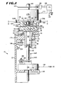
- FIG. 1 shown is a side elevational view entirely in section of a fluid handling apparatus generally indicated by reference character 10.
- the fluid handling apparatus 10 is supported on a suitable bracket 12 which may be affixed to any predetermined support surface.
- the fluid handling apparatus 10 includes a stator member indicated by a reference character 14 and a rotatably movable rotary seal member 16 suppported for rotational movement with respect to the stator 14.
- the stator 14 includes a generally cylindrical valve body portion 22, an elongated reservoir or metering cylinder structure portion 24, these last two elements being threadedly interconnected by a collar 26.
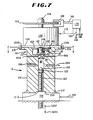
- a collar 26 Although the stator 14 in Figure 1 is shown as configured from the discrete valve body portion 22, metering cylinder structure portion 24 and collar 26, it should be understood that the stator 14 may be formed in the manner illustrated in Figure 7 in which the body portion 22' and the metering cylinder structure portion 24' are integrally formed. Such a construction obviates the need for a collar.
- the valve body portion 22 is a generally cylindrical member formed of a suitable material having a lubricating tendency when another member is frictionally abraded thereagainst.
- Suitable for use as the material used to form the body 22 is an acetal resin material sold by E. I. du Pont de Nemours and Company under the trademark Deirin 8.
- Preferably, off center stock is utilized to avoid porosity.
- other suitable materials such as TFE-fluorocarbon resin or nylon may also be used to form the valve body 22.
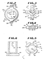
- a pair of opposed arms 32A and 32b extends radially outwardly from the upper end of the valve body 22.
- the arms 32 are provided with oppositely facing slots 34A and 34B ( Figure 2), each of the slots respectively terminating in a notch 36A and 36B for a purpose hereafter disclosed.
- the lower exterior surface of the body portion 22 is provided with threads 42.
- An annular retainer sleeve 46 depends downwardly from the lower surface of the valve body 22.
- the valve body 22 is provided with a counterbore region 48 formed in the upper surface thereof to define a keyway for a purpose hereafter discussed.
- a second bored region 50 extends coaxially with the first counterbore 48 and terminates in a generally planar surface 52.
- a central axial throughbore 56 is provided within the valve body 22 to define a fluid transfer passage through the stator 14. The fluid transfer passage 56 terminates in a frustoconical surface 58.
- An annular surface 60 is defined between the radially inner edge of the frustoconical surface 58 and extends radially outwardly to the base of the sleeve 46.
- the surface 60 is inclined at a predetermined angle (typically about three degrees) to define a substantially annular rim 62 about the frustoconical surface 60.
- At least two but preferably a plurality of fluid conduction passages 66 are provided within the valve body 22.
- any suitable number of fluid conduction passages 66 as are necessary may be conveniently provided in the valve body portion 22.
- the flow passages 66 extend from the cylindrical surface of the valve body 22 intermediate the threads 42 and the arms 32 and open on the flat surface 52 at the base of the counterbore 50.
- the fluid conduction passages 66, as well as the fluid transfer passage 56, are formed with smooth, noncreviced, continuous sidewalls so that fluid conducted or transferred therethrough is not afforded an opening in which to remain. Thus, carry over is minimized.
- the metering cylinder structure 24 is an elongated cylindrical member having a first and a second annular shoulder 74 and 76 formed therein respectively adjacent the upper and intermediate portions of the exterior thereof.
- the member 24 is formed of a suitable material, as stainless steel, although other suitable material, such as acetal resin material sold by E. I. du Pont de Nemours and Company under the trademark Deirin O may be used. If the stator 14 is formed with an integral valve body 22' and metering cylinder structure 24' ( Figure 7), the acetal resin material such as Deirin O is preferred. It should be noted that forming the stator 14 in a manner in which the body 22' and the metering cylinder structure 24' are integral provides the advantage of reduced mill costs. In addition, such an integral structural arrangement further minimizes the possibility of fluid carry over.
- a throughbore 78 having a diameter substantially equal to the diameter of the frustoconical surface 58 in the valve body 22 extends through the member 24.
- the bore 78 can vary in size (diameter and length) consistent with the application to thereby meter appropriately sized volumes of fluid.
- the bore 78 is formed of smooth, noncreviced, continuous sidewalls for the reason discussed above.
- the outside diameter of the upper portion of the member 24 between the flat top surface thereof and the first shoulder72 formed thereon is sized to be snuggly received within the downwardly depending sleeve 46 provided on the valve body 22.
- the rim 62 on the valve body 22 mates against the upper surface of the member 24 adjacent the bore 78 and the body 22 and member 24 cooperate to define a fluid metering volume 80 therein.
- the fluid transfer passage 56 is in fluid communication and coaxially aligned metering volume 80.
- the lower end of the member 24 is provided with a radially extending backflush passage 82 communicating with the metering volume 80.
- the valve body 22 and the member 24 are held in the described assembled relationship by the collar 26.
- the collar 26 includes a generally cylindrical central portion 88 having a cylindrical bore 90 formed therein.
- the bore 90 is coaxial with the passage 56 and the bore 78 and exhibits a dimension substantially equal to the dimension of the sleeve 46 depending downwardly from the body portion 22.
- the collar 26 is counterbored as at 92 to define an upwardly extending annular region having threads 94 provided therein.
- the bore 90 is partially closed by radially inwardly extending annular portion 96 having a diameter substantially equal to the diameter of that portion of the member 24 intermediate the shoulders 74 and 76.
- the stator 14 is formed by threadedly interconnecting the threads 94 on the collar 26 with the threads 42 of the lower portion of the valve body 22 until the annular region 96 adjacent the lower end of the collar 26 is brought into an abutting relationship with the undersurface of the shoulder 74 formed on the member 24.
- the rotary valve seal member 16 ( Figures 3 and 4) is formed of a elastomeric material such as a fluroelastomer material sold by E. I. du Pont de Nemours and Company under the trademark Viton O.
- the seal is removably mountable to a plunger member 102 ( Figures 5 and 6).
- the plunger 102 is a hollow tubular member having an annular flange 104 connected to the lower end thereof.
- the flange 104 has a generally planar annular surface 106 thereon.
- the flange 104 is provided with cutouts 108 which cooperate to define a plurality of radially extending channels 110 defined between an array of feet 112.
- the rotary seal member 16 includes a central cylindrical body portion 124 ( Figures 3 and 4) having a plurality of radially outwardly extending tabs 126 thereon.
- the diametrical dimension 128 of the body portion 124 and the width dimension 130 of the tabs 126 are sized to be respectively received within the cylindrical surface 115 provided on the radially inside edges of the feet 112 and within the channels 110 respectively.
- the radially outward ends 132 of each of the tabs 126 extends a predetermined distance past the outer diameter of the feet 112 so that the rotary seal 120 may be manipulated and manually inserted and removed by an operator.
- the central portion 124 of the seal 16 is provided with a substantially radially extending slot 136 having a predetermined slot width 137 (Figure 3).
- the dimension of the slot width 137 is sized in accordance with the angular distance between the openings of adjacent fluid conduction passages 66 on the surface 52.
- the radial dimension 138 of the slot 132 is sufficient to encompass the radial distance 140 ( Figure 2) (including the dimensions of the openings) between the fluid transfer passage 56 and any one of the fluid conduction passages 66 terminating on the planar surface 52 of the valve body 22.
- the diametric dimension 128 of the rotary seal 120 is preferably any dimension up to 0.30 inch.
- This dimension size serves to reduce the friction generated between the rotary seal 120 and the surface 52 of the stator 14, thus reducing the torque required to rotate the seal 120.
- the radial dimension 138 of the slot 136 may be up to 2,5 mm (0.10 inch).
- the radial dimension 138 and the slot width 137 are selected to reduce the volume of fluid which must be purged from the fluid handling device.
- the plunger 102 is secured as by a pin 142 ( Figure 1) press fit into the depending shaft 146 of a rotary actuator 148.
- the pin 142 extends through an opening 144 provided in the plunger 102.
- Suitable for use as the rotary actuator 148 is a stepping motor such as that sold by Eastern Air Devices under model name Sigma.
- a spring 150 trapped between the rotary actuator 148 and the surface 106 on the plunger 102 biases the seal member 16 toward the stator 14.
- the spring 150 is sized to generate a sealing force to urge the seal member 16 against the surface 52. However, the sealing force is not large enough to create excessive wear.
- the rotary actuator 148 has a generally cylindrical portion 152 which is sized to be closely received within the counterbore region 48 in the valve body 22. Downwardly depending positioning pins 154 extend from a face plate 156 of the rotary actuator 148.
- first direction 158 Figure 2
- the pins 154 thereon are received within the openings 34 on the arms 32 of the valve body 22.
- the arms 32 are resiliently urged outwardly and thereafter closed upon the downwardly depending pins 154 to thereby secure the same into the recesses 36 provided in the arms 32.
- the rotary actuator 148 is removably but firmly secured to the stator 14. Rotation of the rotary actuator 148 in a direction 160 counter to the direction 158 serves to disengage the rotary actuator 148 from the stator 14.
- the upwardly projecting portion of the shaft 146 of the rotary actuator 148 is provided with an encoder wheel 164 operative to provide an indication of the relative position of the slot 136 in the rotary seal member 16 with respect to the planar surface 52 of the stator 14.
- the position indicia on the wheel 164 is read by any suitable device 166 and signals- representative thereof applied on a line 168 to a controller 170.
- the controller 170 may typically take the form of a microprocessor operating under control of a program. Control signals are applied to the rotary actuator 148 on a line 172. In response to signals applied on the line 172 the shaft 146 is rotated in equiangular steps to thereby rotatably move the seal 116 across the flat planar surface 52 of the stator 14.
- the rotary actuator 148 is arranged to rotate the seal member 16 attached thereto from a first position in which the slot 136 permits communication between one of the fluid conduction passages 66A and the fluid transfer passage 56 to a second position in which the fluid transfer passage communicates with the second of the fluid conduction passage 66B.
- the conjoined assembly of the stator 14, rotary seal 16, and rotary actuator 148 are receivable within an opening 176 provided through an arm 178 formed integral with the bracket 12.
- the metering cylinder portion 24 extends through the opening 176 and an abutment is formed between the shoulder 76 on the member 24 and the periphery of the opening 176 in the arm 178.
- the fluid metering volume 80 formed in the stator 14 receives a piston 180 carried at the upper end of a elongated shaft 182 of a linear actuator 184.
- the linear actuator 184 is a suitably supported on an outwardly depending shelf 186 integral with the bracket 12.
- the shaft 182 is displaceable upwardly in a pumping stroke 188P and downwardly in a suction stroke 188S, the directions 188 being parallel to the axis of the metering volume 80. Clearance for the shaft 182 is provided by a cutout 190 provided in the shelf 186.
- the shaft 182 is sealed as it enters the member 24 by an O-ring gasket 192. Control signals to the linear actuator 184 from the controller 170 are carried on a line 194.
- the position of the piston 180 within the metering volume 80 is monitored by a sensor 196 mounted to a shelf 198 of the bracket 12.
- a projecting pin 200 is attached to the shaft 182 by a connector 202. When the pin 200 engages the sensor 196 a signal representative of that occurrence is transmitted to the controller 170 on a line 204.
- the lower end of the metering cylinder portion 24' of the stator 14 is provided with a recess 208 which receives a fitting 210 on the actuator 184.
- the linear actuator 184 may be directly connected to the stator 14 thereby eliminating the requirement of the bracket 12 and compressing the vertical dimension of the fluid handling device 10.
- connectors 212 may be used to further secure the linear actuator 184 to the stator 14.
- fluid communication may be established from a point (as a fluid source) external to the valve 10 through the fluid conduction passage 66A, the slot 136, the fluid transfer passage 56 to the fluid metering volume 80.
- the linear actuator 184 then draws the piston 180 in a suction stroke 188S to draw a predetermined volume of fluid into the volume 80.
- the rotary actuator 148 then rotates the seal member 16 to the second position in which communication between the fluid transfer passage 56 and the second fluid conduction passage 66B is established.
- the linear actuator 184 displaces the piston 180 in a pumping direction 188P, thus positively displacing the fluid within the volume 80 through the transfer passage 56, the slot 136 and the conduction passage 66B to a point external to the apparatus 10.
Landscapes
- General Health & Medical Sciences (AREA)
- Health & Medical Sciences (AREA)
- Life Sciences & Earth Sciences (AREA)
- Chemical & Material Sciences (AREA)
- Analytical Chemistry (AREA)
- Biochemistry (AREA)
- Physics & Mathematics (AREA)
- General Physics & Mathematics (AREA)
- Immunology (AREA)
- Pathology (AREA)
- Sliding Valves (AREA)
- Reciprocating Pumps (AREA)
- Automatic Analysis And Handling Materials Therefor (AREA)
Applications Claiming Priority (2)
| Application Number | Priority Date | Filing Date | Title |
|---|---|---|---|
| US06/296,850 US4428511A (en) | 1981-08-27 | 1981-08-27 | Fluid handling apparatus having a fluid metering volume therein |
| US296850 | 1994-08-26 |
Publications (3)
| Publication Number | Publication Date |
|---|---|
| EP0073466A2 EP0073466A2 (en) | 1983-03-09 |
| EP0073466A3 EP0073466A3 (en) | 1984-03-21 |
| EP0073466B1 true EP0073466B1 (en) | 1987-04-01 |
Family
ID=23143838
Family Applications (1)
| Application Number | Title | Priority Date | Filing Date |
|---|---|---|---|
| EP82107795A Expired EP0073466B1 (en) | 1981-08-27 | 1982-08-25 | Fluid handling apparatus having a fluid metering volume therein |
Country Status (7)
| Country | Link |
|---|---|
| US (1) | US4428511A (el) |
| EP (1) | EP0073466B1 (el) |
| JP (1) | JPS5845567A (el) |
| CA (1) | CA1178086A (el) |
| DE (1) | DE3275947D1 (el) |
| DK (1) | DK381982A (el) |
| GR (1) | GR77242B (el) |
Families Citing this family (12)
| Publication number | Priority date | Publication date | Assignee | Title |
|---|---|---|---|---|
| GB8300883D0 (en) * | 1983-01-13 | 1983-02-16 | Ciba Geigy Ag | Automatic sampling device |
| US4681242A (en) * | 1985-09-05 | 1987-07-21 | Charles Wyle Engineering Corporation | Solvent pump |
| US4869397A (en) * | 1987-06-24 | 1989-09-26 | Liquipak International, Inc. | Adjustable fill motor assembly |
| FR2714181A1 (fr) * | 1993-12-22 | 1995-06-23 | Peters Jean Bernard | Système automatique de répartition d'un liquide biologique. |
| US5623715A (en) * | 1994-08-23 | 1997-04-22 | Clark; Lloyd D. | Liquid toner concentrate management system and method |
| US5630398A (en) * | 1996-06-05 | 1997-05-20 | Cummins Engine Company, Inc. | Stepped rotation fuel distribution valve |
| DE102008002674B9 (de) * | 2008-06-26 | 2010-10-21 | INSTITUT FüR MIKROTECHNIK MAINZ GMBH | Mikroventil und Abdichteinrichtung zur Verwendung in einem Mikrofluidiksystem sowie Verfahren zu deren Herstellung |
| DE102008002675B4 (de) * | 2008-06-26 | 2014-11-06 | INSTITUT FüR MIKROTECHNIK MAINZ GMBH | Abdichteinrichtung zur Verwendung in einem Probeaufbereitungschip sowie Verfahren zu deren Herstellung |
| US8261773B2 (en) * | 2009-07-30 | 2012-09-11 | Idex Health & Science Llc | Multi-position micro-fluidic valve system with removable encoder assembly |
| EP3135965A1 (en) * | 2015-08-31 | 2017-03-01 | bNovate Technologies SA | Pump system with rotary valve |
| EP3135966A1 (en) * | 2015-08-31 | 2017-03-01 | bNovate Technologies SA | Rotary valve |
| WO2017037072A1 (en) * | 2015-08-31 | 2017-03-09 | bNovate Technologies SA | Rotary valve and pump system with rotary valve |
Family Cites Families (5)
| Publication number | Priority date | Publication date | Assignee | Title |
|---|---|---|---|---|
| US3780912A (en) * | 1968-04-02 | 1973-12-25 | Micromedic Systems Inc | Metering and dispensing apparatus |
| CS151687B1 (el) * | 1968-04-09 | 1973-11-19 | ||
| US3664194A (en) * | 1970-09-29 | 1972-05-23 | Dow Chemical Co | Valve assembly for injecting a liquid sample into an analyzing instrument |
| US3864978A (en) * | 1974-02-19 | 1975-02-11 | Envirotech Corp | Automatic rotary sample injection valve |
| US4189943A (en) * | 1975-03-25 | 1980-02-26 | Faure Jean M | Apparatus for volume measurement of liquids |
-
1981
- 1981-08-27 US US06/296,850 patent/US4428511A/en not_active Expired - Lifetime
-
1982
- 1982-08-25 EP EP82107795A patent/EP0073466B1/en not_active Expired
- 1982-08-25 DE DE8282107795T patent/DE3275947D1/de not_active Expired
- 1982-08-26 JP JP57146992A patent/JPS5845567A/ja active Pending
- 1982-08-26 DK DK381982A patent/DK381982A/da not_active Application Discontinuation
- 1982-08-26 CA CA000410186A patent/CA1178086A/en not_active Expired
- 1982-08-27 GR GR69139A patent/GR77242B/el unknown
Also Published As
| Publication number | Publication date |
|---|---|
| GR77242B (el) | 1984-09-11 |
| US4428511A (en) | 1984-01-31 |
| DE3275947D1 (en) | 1987-05-07 |
| DK381982A (da) | 1983-02-28 |
| CA1178086A (en) | 1984-11-20 |
| EP0073466A2 (en) | 1983-03-09 |
| JPS5845567A (ja) | 1983-03-16 |
| EP0073466A3 (en) | 1984-03-21 |
Similar Documents
| Publication | Publication Date | Title |
|---|---|---|
| EP0073466B1 (en) | Fluid handling apparatus having a fluid metering volume therein | |
| US5063790A (en) | Pipette tip pickup apparatus | |
| US6846680B2 (en) | Liquid handling system with automatically interchangeable cannula array | |
| EP2945744B1 (en) | Liquid end assembly for a multichannel air displacement pipette | |
| US5617879A (en) | Sealing arrangement for a coolant union having a floating seal assembly | |
| AU598711B2 (en) | Peristaltic pump adapted to operate simultaneously on two lines | |
| EP2190582B1 (en) | Multi-channel pipette including a piston holder with guidance | |
| US4598840A (en) | Snap-in cartridge diluter | |
| SU1050550A3 (ru) | Центробежное устройство дл анализа жидких проб | |
| EP0279966A1 (en) | Improved fluid metering device | |
| US4359447A (en) | Automatic multichannel apparatus for performing emergency analyses, in particular chemical-clinical analyses on biological fluids | |
| EP0175046A1 (en) | Valve device | |
| EP0591449B1 (en) | Apparatus for calibrating a multiple port pump | |
| DE3931544A1 (de) | Tauchkolbenpumpe | |
| JPH01502847A (ja) | 分析器の選択送り出し装置 | |
| US4653673A (en) | Pump for precisely dispensing liquids | |
| US6106383A (en) | Integral air gage for releasable cylindrical tool body | |
| CA2439891A1 (en) | Apparatus and method for processing and testing a biological specimen | |
| JPH0134125Y2 (el) | ||
| WO1993015316A1 (en) | Valveless metering pump with reciprocating, rotating piston | |
| US3990224A (en) | Open end spinning machine | |
| CN218237020U (zh) | 一种用于机器人轴承自动涂油装置 | |
| CN219663391U (zh) | 微流体混合设备 | |
| CN118254019B (zh) | 一种离心泵泵壳钻孔设备 | |
| CN215292830U (zh) | 蠕动式给料泵和包括蠕动式给料泵的设备 |
Legal Events
| Date | Code | Title | Description |
|---|---|---|---|
| PUAI | Public reference made under article 153(3) epc to a published international application that has entered the european phase |
Free format text: ORIGINAL CODE: 0009012 |
|
| 17P | Request for examination filed |
Effective date: 19820825 |
|
| AK | Designated contracting states |
Designated state(s): BE DE FR GB IT LU NL |
|
| PUAL | Search report despatched |
Free format text: ORIGINAL CODE: 0009013 |
|
| AK | Designated contracting states |
Designated state(s): BE DE FR GB IT LU NL |
|
| GRAA | (expected) grant |
Free format text: ORIGINAL CODE: 0009210 |
|
| AK | Designated contracting states |
Kind code of ref document: B1 Designated state(s): BE DE FR GB IT LU NL |
|
| PG25 | Lapsed in a contracting state [announced via postgrant information from national office to epo] |
Ref country code: IT Free format text: LAPSE BECAUSE OF FAILURE TO SUBMIT A TRANSLATION OF THE DESCRIPTION OR TO PAY THE FEE WITHIN THE PRESCRIBED TIME-LIMIT;WARNING: LAPSES OF ITALIAN PATENTS WITH EFFECTIVE DATE BEFORE 2007 MAY HAVE OCCURRED AT ANY TIME BEFORE 2007. THE CORRECT EFFECTIVE DATE MAY BE DIFFERENT FROM THE ONE RECORDED. Effective date: 19870401 Ref country code: FR Free format text: THE PATENT HAS BEEN ANNULLED BY A DECISION OF A NATIONAL AUTHORITY Effective date: 19870401 Ref country code: BE Effective date: 19870401 |
|
| REF | Corresponds to: |
Ref document number: 3275947 Country of ref document: DE Date of ref document: 19870507 |
|
| EN | Fr: translation not filed | ||
| PG25 | Lapsed in a contracting state [announced via postgrant information from national office to epo] |
Ref country code: LU Free format text: LAPSE BECAUSE OF NON-PAYMENT OF DUE FEES Effective date: 19870831 |
|
| PLBE | No opposition filed within time limit |
Free format text: ORIGINAL CODE: 0009261 |
|
| STAA | Information on the status of an ep patent application or granted ep patent |
Free format text: STATUS: NO OPPOSITION FILED WITHIN TIME LIMIT |
|
| PG25 | Lapsed in a contracting state [announced via postgrant information from national office to epo] |
Ref country code: NL Effective date: 19880301 |
|
| 26N | No opposition filed | ||
| NLV4 | Nl: lapsed or anulled due to non-payment of the annual fee | ||
| PG25 | Lapsed in a contracting state [announced via postgrant information from national office to epo] |
Ref country code: DE Effective date: 19880503 |
|
| GBPC | Gb: european patent ceased through non-payment of renewal fee | ||
| PG25 | Lapsed in a contracting state [announced via postgrant information from national office to epo] |
Ref country code: GB Free format text: LAPSE BECAUSE OF NON-PAYMENT OF DUE FEES Effective date: 19881121 |