EP0073322A1 - Device for controlling tightness of vapour pipes - Google Patents
Device for controlling tightness of vapour pipes Download PDFInfo
- Publication number
- EP0073322A1 EP0073322A1 EP82106206A EP82106206A EP0073322A1 EP 0073322 A1 EP0073322 A1 EP 0073322A1 EP 82106206 A EP82106206 A EP 82106206A EP 82106206 A EP82106206 A EP 82106206A EP 0073322 A1 EP0073322 A1 EP 0073322A1
- Authority
- EP
- European Patent Office
- Prior art keywords
- temperature
- cable
- monitoring device
- measuring cable
- humidity measuring
- Prior art date
- Legal status (The legal status is an assumption and is not a legal conclusion. Google has not performed a legal analysis and makes no representation as to the accuracy of the status listed.)
- Granted
Links
Images


Classifications
-
- G—PHYSICS
- G21—NUCLEAR PHYSICS; NUCLEAR ENGINEERING
- G21C—NUCLEAR REACTORS
- G21C17/00—Monitoring; Testing ; Maintaining
- G21C17/10—Structural combination of fuel element, control rod, reactor core, or moderator structure with sensitive instruments, e.g. for measuring radioactivity, strain
- G21C17/112—Measuring temperature
-
- G—PHYSICS
- G01—MEASURING; TESTING
- G01K—MEASURING TEMPERATURE; MEASURING QUANTITY OF HEAT; THERMALLY-SENSITIVE ELEMENTS NOT OTHERWISE PROVIDED FOR
- G01K1/00—Details of thermometers not specially adapted for particular types of thermometer
- G01K1/14—Supports; Fastening devices; Arrangements for mounting thermometers in particular locations
- G01K1/143—Supports; Fastening devices; Arrangements for mounting thermometers in particular locations for measuring surface temperatures
-
- G—PHYSICS
- G01—MEASURING; TESTING
- G01K—MEASURING TEMPERATURE; MEASURING QUANTITY OF HEAT; THERMALLY-SENSITIVE ELEMENTS NOT OTHERWISE PROVIDED FOR
- G01K7/00—Measuring temperature based on the use of electric or magnetic elements directly sensitive to heat ; Power supply therefor, e.g. using thermoelectric elements
- G01K7/16—Measuring temperature based on the use of electric or magnetic elements directly sensitive to heat ; Power supply therefor, e.g. using thermoelectric elements using resistive elements
- G01K7/18—Measuring temperature based on the use of electric or magnetic elements directly sensitive to heat ; Power supply therefor, e.g. using thermoelectric elements using resistive elements the element being a linear resistance, e.g. platinum resistance thermometer
-
- G—PHYSICS
- G01—MEASURING; TESTING
- G01M—TESTING STATIC OR DYNAMIC BALANCE OF MACHINES OR STRUCTURES; TESTING OF STRUCTURES OR APPARATUS, NOT OTHERWISE PROVIDED FOR
- G01M3/00—Investigating fluid-tightness of structures
- G01M3/002—Investigating fluid-tightness of structures by using thermal means
-
- G—PHYSICS
- G01—MEASURING; TESTING
- G01M—TESTING STATIC OR DYNAMIC BALANCE OF MACHINES OR STRUCTURES; TESTING OF STRUCTURES OR APPARATUS, NOT OTHERWISE PROVIDED FOR
- G01M3/00—Investigating fluid-tightness of structures
- G01M3/02—Investigating fluid-tightness of structures by using fluid or vacuum
- G01M3/04—Investigating fluid-tightness of structures by using fluid or vacuum by detecting the presence of fluid at the leakage point
- G01M3/16—Investigating fluid-tightness of structures by using fluid or vacuum by detecting the presence of fluid at the leakage point using electric detection means
- G01M3/165—Investigating fluid-tightness of structures by using fluid or vacuum by detecting the presence of fluid at the leakage point using electric detection means by means of cables or similar elongated devices, e.g. tapes
-
- G—PHYSICS
- G01—MEASURING; TESTING
- G01N—INVESTIGATING OR ANALYSING MATERIALS BY DETERMINING THEIR CHEMICAL OR PHYSICAL PROPERTIES
- G01N33/00—Investigating or analysing materials by specific methods not covered by groups G01N1/00 - G01N31/00
- G01N33/0004—Gaseous mixtures, e.g. polluted air
- G01N33/0009—General constructional details of gas analysers, e.g. portable test equipment
- G01N33/0027—General constructional details of gas analysers, e.g. portable test equipment concerning the detector
- G01N33/0031—General constructional details of gas analysers, e.g. portable test equipment concerning the detector comprising two or more sensors, e.g. a sensor array
- G01N33/0032—General constructional details of gas analysers, e.g. portable test equipment concerning the detector comprising two or more sensors, e.g. a sensor array using two or more different physical functioning modes
-
- Y—GENERAL TAGGING OF NEW TECHNOLOGICAL DEVELOPMENTS; GENERAL TAGGING OF CROSS-SECTIONAL TECHNOLOGIES SPANNING OVER SEVERAL SECTIONS OF THE IPC; TECHNICAL SUBJECTS COVERED BY FORMER USPC CROSS-REFERENCE ART COLLECTIONS [XRACs] AND DIGESTS
- Y02—TECHNOLOGIES OR APPLICATIONS FOR MITIGATION OR ADAPTATION AGAINST CLIMATE CHANGE
- Y02E—REDUCTION OF GREENHOUSE GAS [GHG] EMISSIONS, RELATED TO ENERGY GENERATION, TRANSMISSION OR DISTRIBUTION
- Y02E30/00—Energy generation of nuclear origin
- Y02E30/30—Nuclear fission reactors
Definitions
- the invention relates to a monitoring device with the features of the preamble of claim 1.
- the object of the invention is to improve a monitoring device of the type described in the introduction in such a way that a substantial saving in various components, a space saving and a high degree of functionality can be achieved.
- An advantage achieved with the invention is that the temperature and humidity monitoring can be carried out via a modularly combined temperature-humidity measuring cable, only two wires with a hygroscopic insulator arranged between them being necessary both for the detection of a change in humidity and a change in temperature are, so that a very simple sensor cable is given for several measurement functions at the same time.
- the temperature-humidity measuring cable according to the invention is extremely inexpensive to manufacture and has a long service life because the parts used are open are reduced to a minimum.
- the temperature-humidity measuring cable is very narrow and requires a negligible amount of space when mounting on the steam pipe, so that a mounting position adapted to the respective requirements can always be carried out.
- the temperature-humidity measuring cable according to the invention enables essentially trouble-free continuous monitoring even over greater distances.
- the temperature-humidity measuring cable is particularly suitable for an extremely high measuring sensitivity, so that any leaks can be detected early, even in the slightest approach. Since the temperature-humidity measuring cable is designed as a multi-function line, there is absolutely no maintenance. since no individual components need to be readjusted or replaced. If steam escapes from the wall of the steam pipe in the event of a leak, a temperature change takes place which is immediately detected by the resistance wire. At the same time, moisture accumulation takes place in the hygroscope isolator.
- the conductor wire of the temperature-humidity measuring cable can advantageously consist of a strand formed from individual wires, as a result of which a high degree of flexibility can be achieved and, moreover, the risk of breakage of the conductor wire is largely eliminated.
- the hygroscope insulator can expediently be designed as a sheath surrounding the conductor wire and, for high resistance to external influences, in particular also radioactive radiation, can consist of a mineral substance, with fiberglass insulation being particularly advantageous for production and application reasons.
- the glass silk insulation can be designed as a fabric tube, braid or web.
- Hy g rosko p iso l ator For example, moisture absorbent pulp, od of paper layers, like produce, but mineral materials such as ceramic or glass not only the advantage of a higher mechanical strength but also just a high radiation resistance have, so that even with continuous radiation exposure there is a long service life, which is why the temperature-humidity measuring cable according to the invention can also preferably be used in the nuclear power sector for monitoring corresponding line systems and the like.
- the strength of the hygroscope isolator can be in the range between 0.01 and 1mm.
- the thickness of the hygroscope isolator is preferably approximately 0.1 to 0.4 mm, since on the one hand there is a practical insulation spacing and on the other hand there is a high measurement sensitivity, which enables precise monitoring.
- the resistance wire of the temperature-humidity measuring cable can advantageously be wound in the form of a screw spiral around the hygroscope insulator encasing the conductor wire.
- the distance between the coils can be approximately in the range between 0.3 to 10 mm, and a favorable distance required for practical requirements can be approximately 0.5 to 4 mm.
- the resistance can be varied or precisely adapted with a corresponding change in distance.
- a certain intrinsic stiffness of the flexible temperature-humidity measuring cable is achieved, which enables better handling during assembly, since a possible / troublesome lumpiness of the cable is avoided.
- the temperature-humidity measuring cable according to the invention with a moisture-permeable outer sheath, which envelops the conductor wire, the hygroscope insulator and the resistance wire in a form-fitting manner.
- a moisture-permeable outer sheath which envelops the conductor wire, the hygroscope insulator and the resistance wire in a form-fitting manner.
- Such an outer jacket can expediently also consist of a mineral material and advantageously be designed as a glass silk fabric hose.
- Such an outer jacket firstly increases the strength against external mechanical stresses, so that use under rough operating conditions is also readily possible.
- the tubular outer sheath which is expediently designed as a flexible fabric or web, also provides freedom from potential, so that there are practically no interferences from outside voltages, contact resistances or the like. can impair the measuring system.
- an electronic evaluation part is expediently assigned to the temperature-moisture measuring cable according to the invention, which has a temperature measuring part and a moisture measuring part. Furthermore, a display part for a possible wire break of the moisture measurement can be provided and it is also possible to also indicate a possible wire break, so that leakage and temperature-detecting leakage monitoring and self-monitoring of the measuring system with regard to its functionality can be achieved.
- two ends of the resistance wire associated with the temperature-humidity measuring cable can advantageously be assigned to the temperature measuring part and two ends of the conductor wire to the conductor wire breakage display part in the electronic evaluation part.
- a line part of the conductor wire and a part line of the resistance wire of the temperature-humidity measuring cable in the region of the evaluation part are expediently fed to the moisture measuring part of the electronic evaluation part.
- the temperature-humidity measuring cable For monitoring, it can be favorable to arrange the temperature-humidity measuring cable according to the invention in the area of a heat insulation surrounding the steam pipe or the like. In this case, it may be expedient to make the arrangement in such a way that the temperature-humidity measuring cable comes to lie close to an inner side of a covering which comprises the thermal insulation. A condensate of a possibly escaping steam that forms in this area is here from the hygroscopic moisture sensor indirectly recorded. Likewise, any temperature change that occurs is immediately detected by the temperature-humidity measuring cable.
- the temperature-humidity measuring cable can advantageously be arranged in the longitudinal direction of the steam pipe or the like, as a result of which linear path monitoring is possible.
- the temperature-humidity measuring cable can expediently be arranged in a groove in the area of the thermal insulation, the groove being able to be closed to the outside by a cover part which is essentially designed as a strip, so that the measuring cable is reliably shielded from external influences.
- the temperature-humidity measuring cable it is possible to arrange the temperature-humidity measuring cable practically in a ring around the steam pipe and to store it in a corresponding circumferential groove. This can be beneficial, for example, in the area of insulation joints and pipe connection points.
- the conductor wire in the temperature-moisture measuring cable such that it consists of two separate wire conductor strands.
- the two wire conductor strands can run parallel to one another.
- the hygroscope isolator is located between them.
- the moisture measurement takes place exclusively via the two wire conductor strands, so that the two measuring systems are so separated from one another that they cannot influence one another. It is one simple sensor cable for several measuring functions, which reliably ensures potential-free measurements.
- the wire conductor strands in the temperature-humidity measuring cable are expediently designed as strands which are formed from thin copper wires, so that practical flexibility is achieved.
- the hygroscope insulator can advantageously be designed as a sheath in the form of a woven or braided glass silk insulation tube, it being favorable to surround each individual wire conductor strand with a glass silk sheath.
- the two wire conductor strands with their hygroscopic insulator can also be surrounded by another moisture-permeable insulator, which can also be a fabric tube made of glass silk, in which the wire conductor strands are combined.
- the resistance wire of the temperature-humidity measuring cable can advantageously be attached to this insulator which summarizes the wire conductor strands, it being favorable to arrange this resistance wire on the insulator in a spiral or helically wound manner.
- the temperature-humidity measuring cable can have an outer sheath which is permeable to moisture and is also expediently designed as a braided or woven glass silk tube.
- the various glass fiber insulations described above not only result in high strength against external mechanical stresses, but are also largely resistant to other materials and also ensure high temperature resistance in continuous use.
- the base load resistance between the two wire conductor strands can preferably be provided at the end of the temperature-humidity measuring cable, which is at least electrically seen from the connection.
- a preferably 4-pin plug socket can be provided, into which a corresponding plug of a measuring line can be inserted, preferably in a moisture and dust-tight manner.
- a return conductor for the resistance wire which is preferably connected to the end of the resistance wire by a soldered or welded connection.
- the return conductor expediently has temperature-resistant insulation, which can be made of Teflon or glass fiber, for example.
- the resistance or the change in resistance between the beginning of the resistance wire and the end thereof is detected for the temperature measurement, the return being carried out by the return conductor from the outermost end remote from the connection of the temperature-humidity measuring cable.
- the return conductor can be on the outside of the temperature-humidity measuring cable and can be attached to the latter, for example, by means of elastic or rubber-like retaining rings.
- the return conductor consists predominantly of a copper strand, which can also run essentially parallel to the wire conductor strands within the outer sheath of the temperature-humidity measuring cable, the return conductor both in the area between the resistance wire and the outer sheath and in the area directly can lie next to the wire conductor strands. It is also possible to design the return conductor of the resistance wire, for example, from thin copper wires as a braided sleeve.
- the temperature-humidity measuring cable can be laid freely, for example in the area of a particularly stuffed thermal insulation, in such a way that it extends both in the longitudinal direction and in the circumferential direction of the steam pipe or the container or the like.
- a preferred position is seen in the area between the wall of the steam pipe and the outer covering of the thermal insulation near the inner surface of the covering, although as already stated there are basically no restrictions here, so that an optimal installation of the temperature-humidity in each case according to the local requirements.
- Measuring cable can be carried out for a perfect leak detection.
- the temperature-humidity measuring cable on a flat band, which is flexible in that it can be looped around a pipe or its thermal insulation, for example, like a tension band.
- the flat tape can consist of a high quality version made of a rustproof and antimagnetic stainless steel and it can have a tension lock which can be adjusted essentially in fine steps, so that any tolerances in the area of thermal insulation can be easily compensated for during installation on the steam pipe, whereby in any case one a perfect fit of the tensioning strap and thus of the temperature-humidity measuring cable is ensured.
- the temperature-humidity measuring cable can advantageously be attached via a clamping block, which, for example, consists of a elastic and temperature-resistant silicone rubber is manufactured and attached to the ribbon with a clamp.
- the clamping block may have one or even two longitudinal grooves in which the temperature-humidity at the side facing the flat side - is mounted measuring cable and is guided, wherein, in a loop-shaped arrangement of the flat strip temperature-humidity-measuring cable in a longitudinal groove of the VorISSraitkowskiteil and in the other longitudinal groove of the return cable part of the temperature-humidity measuring cable is.
- an insulating film can be provided between the tensioning block and the flat strip, so that the outer sheath of the temperature-moisture measuring cable in the area of the tensioning block does not come into direct contact with the flat strip even when subjected to pressure.
- the insulating film can consist of Kapton or the like.
- the clamping bracket for the clamping block can be detachably fastened to the clamping band by means of screws. However, it is also possible to fasten the clamping bracket using rivets or spot welding.
- the clamping bracket can have limiting webs on both sides, the free ends of which are advantageously bent or rounded obliquely for problem-free insertion into a groove.
- the tensioning blocks and clamping brackets can be arranged approximately at fifteen centimeters from one another in the longitudinal direction of the flat strip in the central region thereof. If the temperature-humidity measuring cable is designed as a cable loop with a demonstration cable part and a return cable part, it is favorable to avoid lateral cable bends to arrange the demonstration cable part and the return cable part between two clamping blocks so that they cross.
- the cable parts between the clamping blocks do not bulge out to the side, but continue to run essentially in their predetermined longitudinal direction, so that temperature-humidity measuring cables safely reach the area of the groove in the heat insulation and do not between them outer casing and the strap is clamped.
- the ribbon with the sensor cable can advantageously be arranged in the region of a joint of the thermal insulation, which can be designed, for example, as a cassette insulation.
- the flat strip covers a groove that connects to the joint in the upper area of the thermal insulation.
- the measuring cable reaches the area of the groove, the clamping brackets with their lateral limiting webs running close to the side walls of the groove, so that a security against lateral displacement of the flat strip is ensured.
- the connection of the temperature-humidity measuring cable can be sealed in a connection block in the area of the plug socket, which is advantageously fastened or screwed to the flat strip in the area of a hole.
- connection block preferably consists of a moisture-proof and electrically insulating casting resin and is advantageously designed and arranged such that it lies in the longitudinal direction of the flat strip essentially in one plane with the clamping block or the clamping bracket and also has approximately the same width as the clamping bracket, so that the terminal block also engages centering in the groove when tightening the flat strip and thus contributes to securing against any lateral displacement.
- a sealing strip can be arranged in order to achieve an extensive seal.
- the sealing strip can run in the region of the longitudinal side edges of the flat strip.
- the sealing strip can consist of an elastomer, which can be designed, for example, as a foam with closed or open cells.
- the sealing strip can also be designed to be adhesive on one or both sides for attachment to the flat strip and / or to the covering.
- the groove in the area of the heat insulation can have an essentially rectangular cross-section, wherein the adjacent joint of the heat insulation can be located anywhere in the center of the groove or on one side.
- the groove base can be designed so that it extends essentially obliquely outwards from the joint towards the side edge of the flat strip, so that in the event of a leak, the detection of the steam portion preferably emerging from the joint can be favored.
- the oblique course of the groove base can be made substantially V-shaped on both sides. But it is also possible to design the groove base as a single slope.
- the groove can also be designed in such a way that there is a gradation in which the flat strip can be substantially recessed or recessed, so that there is practically no protrusion to the outside of the circumference of the heat insulation.
- the temperature-humidity measuring cable can be assigned electronic measured value processing with transducers for temperature and humidity detection, whereby such measured value processing can advantageously also be associated with a control computer system, which preferably has two independent microcomputers for temperature and humidity detection Data query, error message and possibly also printer control can have. An alarm system is also provided for detection.
- the temperature-humidity measuring cable according to the invention can preferably be arranged in a nuclear power plant for leak detection, in particular in a gully inserted into a floor of a room. be applied.
- the sensor cable can be provided on an insert body which is stored in the gully.
- Moisture measuring cables for this purpose are located in a circumferential recess of the insert body, in such a way that the outer diameter in Range is about stored the sensor cable equal to or slightly greater than the rest diameter of the insert body, so that the D e tektionstiv in the circumferential groove substantially protected and there is still a free access for the absorption of moisture.
- the temperature-humidity measuring cable can run in several turns, preferably two to five turns, like a screw thread around the insert body.
- the temperature-humidity measuring cable can be assigned a plug socket, which is designed, for example, with four poles, the beginning and the end of the sensor cable being connected here.
- the plug socket is advantageously arranged insulated in the insert body in such a way that there is a moisture-tight seal, in particular in the connection area of the detection cable.
- the plug socket and the insert body with the integrated temperature-humidity measuring cable thus essentially form a single compact unit which reliably meets the practical requirements both during assembly and during later continuous operation.
- the plug socket can be held essentially in the central region of the insert body via radial support struts.
- the insert body can be designed to be conically tapered downwards and can have a pivotable handle in its upper area, in particular for easy removal from the gully.
- the insert body can be made of plastic, stainless steel can also be used.
- the temperature-humidity measuring cable can extend from the outer wall of the insert body to that in the middle area arranged socket run under one of the radial support struts in its cross-sectional area in a corresponding recess, so that protected storage is ensured in any case.
- the insert body with the sensor cable can be mounted in a container part designed as a tube.
- This tubular container part can be fastened to the inner surface of a ring which can be inserted into the gully, so that the insert body is arranged off-center.
- a trough-shaped liquid supply can be provided in the fastening area of the tubular container part on the ring, through which any leakage liquid is positively guided into the pipe container part and thus to the temperature-moisture measuring cable located on the insert body.
- the insert body is mounted largely free of play in the tubular container part. Any liquid flowing in from above can flow freely out of the tube container part after passing through the sensor cable.
- the ring can have a circumferential groove with an O-ring, so that when inserted into the gully on the outer circumference of the ring there is a tight seal and any liquid cannot flow past the outside of the ring.
- a change in humidity but also a change in temperature can also be detected in this gully monitoring system, so that here too two parameters are guaranteed for unambiguous and reliable leak detection if, for example, liquid emerges from a pipe system, a container or the like and enters reaches the gully, whereby slight temperature differences between the leakage liquid and the room temperature are detected.
- the gully monitoring according to the invention with the present temperature Humidity measuring cables can be suitably assigned to a processing of measured values, preferably using transmitters, evaluation electronics, control systems (printers), alarm devices and the like: Gully monitoring is particularly important at those places that people should not normally visit. These are, for example, existing premises in a nuclear power plant, which, for example, may only be entered in exceptional cases or at great intervals due to a radioactive radiation hazard for safety reasons.
- the proposed drain monitoring system enables continuous remote monitoring, which has a high level of operational reliability with reliable continuous function and works potential-free, so that external interference is practically avoided.
- the proposed gully monitoring system is also relatively inexpensive to manufacture and install, so that all the gullies in question in the area of a power plant facility to be monitored can be recorded while avoiding a disproportionately high cost, especially since any subsequent costs practically do not occur after the gully monitoring system has been installed or reduced to a minimum.
- the two wire conductor strands in the temperature-moisture measuring cable are fed to a moisture measuring part, via which a change in resistance in the M-ohm range between the wire conductor strands on the hygroscope isolator is detected.
- an electrical voltage can optionally be applied to the resistance wire of the temperature-humidity measuring cable that the resistance wire acts as an electrical heating element.
- This measure according to the invention can also be used to dry any moisture accumulations with one and the same sensor cable can be achieved, which can be advantageous, for example, for carrying out a control measurement in the case of a previous signal.
- the temperature-humidity measuring cable 1 shown in the drawing is used to monitor a steam pipe 2 or the like. In the event of a leak, changes in moisture and temperature due to the escaping steam are detected.
- the astonishingly simple temperature-humidity measuring cable 1 according to the invention which is thus a multi-functional and structurally combined sensor cable, has a central conductor wire 3, which is preferably made of copper and is designed as a strand formed from thin individual wires 4.
- the conductor wire 4 of the temperature-humidity measuring cable 1 is surrounded by a moisture-absorbing hygroscope insulator 5, which in the present exemplary embodiment is designed as a tubular sheath and consists of a glass silk insulation which advantageously has finely spun or woven glass fiber threads.
- a moisture-absorbing hygroscope insulator 5 which in the present exemplary embodiment is designed as a tubular sheath and consists of a glass silk insulation which advantageously has finely spun or woven glass fiber threads.
- the wall thickness of the hygroscope isolator 5 is about 0.3 mm in the present case.
- Parallel to the conductor wire 3 runs in the longitudinal direction of a thin resistance wire 6, which is wound practically helically around the hygroscopic insulator 5, so that a constant constant through the latter Distance to the conductor wire 3 is given.
- the resistance wire 6 is appropriately wound so that the distances between the coils are approximately 1 mm, but it is also within the scope of the invention to make the coil spacings larger or smaller. Due to the helical design of the resistance wire 6, the temperature-humidity measuring cable 1 has a certain inherent stiffness and the advantage of a largely tight or narrow measurement detection on the circumference is also achieved.
- the temperature-humidity measuring cable 1 has an outer jacket 7, which encloses the conductor wire 3, the hygroscope insulator 5 and the resistance wire 6 in a tubular manner.
- This outer jacket 7 expediently also consists of a mineral material and, in the present exemplary embodiment, was produced from glass silk threads, which are processed to form a mechanically strong, but nevertheless moisture-permeable fabric hose.
- the temperature-humidity measuring cable 1 is arranged in the longitudinal direction of the steam pipe 2 in the area of a thermal insulation 8 which surrounds the wall 9 of the steam pipe 2.
- the arrangement is such that the temperature-humidity measuring cable 1 is located near the inside of an outer jacket 10, which can be designed as a sheet metal jacket or a plastic jacket.
- the temperature-humidity measuring cable 1 is embodied here as a cable loop 11, a deflected return cable part 12 running essentially parallel to a demonstration cable part 13, which are connected at one end to a plug part 14 which protrudes from the sheath 10.
- the plug part 14 has two connection poles 15, 15 'for the resistance wire 6 and two pole connections 16, 16' for the conductor wire 3.
- temperature humidity to the invention is - measuring cable 1 located in a groove 17, which is designed as a radial circumferential groove 18 and the thermal insulation is in the region of an impact point 8.
- the groove 17 is closed on the outside by a flat band-shaped cover part 19, so that the temperature-humidity measuring cable 1 is securely shielded.
- the temperature-humidity measuring cable 1 is arranged in a loop in the groove 17, so that there is a forward and a return.
- a preferably electronic evaluation part 20 which comprises a temperature measuring part 21, a moisture measuring part 22 and a conductor part breakage indicating part 23. It can be seen that two ends of the resistance wire 6 associated with the temperature-humidity measuring cable 1 are fed to the temperature measuring part 21. The two ends of the lead wire 3 are fed to the lead wire bruise display part 23.
- the moisture measuring part 22 is assigned a line part 24 belonging to the conductor wire 3 and a part line 25 belonging to the resistance wire 6.
- the line part 24 and the partial line 25 are expediently tapped or connected in the area of the evaluation part 20 at corresponding points.
- the temperature-humidity measuring cable 101 shown in the drawing is part of a monitoring device for leakage detection in containers or the like that absorb or contain liquid or steam, for example. It is designed as a multifunctional sensor cable and has two wire conductor strands 103, 104 that act as conductor wire 102. The latter consist of thin copper single wires, so that they are designed as so-called strands, which include a certain flexibility. Both wire conductor strands 103, 104 are each individually provided with a hygroscope insulator 105, which in the present exemplary embodiment is designed as a braided glass-fiber tube sheath.
- the two wire conductor strands 103, 104 and the hygroscope insulator 105 are located in a further insulator 106, which is also permeable to moisture and is designed here as a tubular glass fiber fabric.
- a resistance wire 107 which is used for temperature measurement, is wound around the insulator 106 in a helical or screw thread-like manner, while the two wire conductor strands 103, 104 with the hygroscope insulator 105 are intended for moisture measurement, the wire conductor strands 103, 104 being fed to a moisture measuring part, via which a change in resistance in the Ohm range between the wire conductor strands 103,104 is detected.
- Temperature and humidity are thus detected in the detection cable 101 according to the invention with sensors that are completely separated from one another, so that no mutual interference can occur and potential-free measurement results are achieved in any case.
- the resistance wire 107 which is associated with a temperature measuring part, can, if necessary, also be applied with such an electrical voltage (switchover) that the resistance wire 107 works as an electrical heating element. This makes it easy to remove any moisture in the temperature-humidity measuring cable 101 and in the vicinity by drying quickly.
- temperature-humidity measuring cable 101 has an outer sheath 108, which consists of a tubular glass fiber fabric and the aforementioned wire conductor strands 103, 104, their hygroscopic insulator 105, the insulator 106 and the resistance wire 107.
- a return conductor 109 bears against the outer jacket 108, which can be fixed to the outer jacket 108 with corresponding elastic retaining rings or the like.
- the return conductor 109 is provided on the outside with a temperature-resistant Teflon insulation 110, wherein silicone rubber or glass silk can also be provided.
- the return conductor 109 can be connected to the end of the resistance wire 107 by means of a soldered or welded connection, for example if the temperature-humidity measuring cable 101 is not returned to the return line.
- the temperature-humidity measuring cable 111 shown in FIG. 6 is designed essentially like the temperature-humidity measuring cable 101 described above. Therefore, the matching parts have the same reference numerals. The main difference is that in the temperature-humidity measuring cable 111, the return conductor 112 runs parallel to the wire conductor strands 103, 104 inside the tubular insulator 106. It is also within the scope of the invention to provide the return conductor 112, for example, as a copper braid under the insulator 106.
- the temperature-humidity measuring cable 101, 111 can be laid largely freely, essentially without any particular restrictions, so that any arrangement along a pipeline can preferably take place in a stuffed insulation.
- the temperature-humidity measuring cable 101 has a connection block 113 with a multi-pin plug socket 114. This is stored in the connection block 113 in a moisture-proof, electrically insulated manner, since the connection block 113 consists of a corresponding casting resin, which can preferably be temperature-resistant as well as elastic.
- the temperature-humidity measuring cable 101 has a base load resistor 115, which is arranged between the wire conductor strands 103, 104 used for moisture detection and can also be used for wire break monitoring.
- the temperature-humidity measurement cable 101 is implemented as a set on a flat ribbon cable 117 loop 118 having a Vorgrad mecanicteil 119 and a return cable portion 120.
- the flat strip can consist of an approximately 1.5 mm thin stainless steel sheet, at one end of which a swivel lever-operated tension lock 121 is arranged for a quick release fastener, which can be finely adjusted via a threaded part for tolerance compensation and at the other end region of the flat strip 117 into an abutment 122 intervenes.
- the temperature-humidity measuring cable 101 is mounted with its demonstration cable part 119 and its return cable part 120 in longitudinal grooves 123 of a plurality of clamping blocks 124.
- the clamping blocks 124 are attached to the flat belt 117 at substantially equal intervals of approximately 50 cm and, in a preferred embodiment, consist of rubber-elastic silicone rubber which, in addition to its good electrical insulation properties, has a high permanent temperature resistance.
- An insulating film 125 for example made of Kapton, can additionally be arranged under the clamping block 124, so that high-quality insulation is provided between the temperature-humidity measuring cable 101 and the flat ribbon 117 for shielding against external interferences, even for a potential-free measurement implementation.
- the clamping blocks 124 are each fastened with a clamping bracket 126 which is detachably arranged on the flat belt 117 by means of screws 127.
- Each clamping bracket 126 has on both sides of the flat strip 117 striving limiting webs 128, the free ends of which are rounded in an arc. It can also be seen that the demonstration cable part 119 and the return cable part 120 each run in the area between two clamping blocks 124 in such a way that they intersect. This prevents the demonstration cable part 119 and the return cable part from bending when the ribbon 117 is bent into a circle 120 Bend outward in an arc. It can also be seen that the width of the terminal block 113 is substantially equal to the width of the clamping bracket 126 and lies in the same central plane as seen in the longitudinal direction of the flat strip 117. In the clamping block 124 located away from the connection block 113, a transverse groove is formed between the longitudinal grooves 123, in which the deflection of the temperature-humidity measuring cable 101 takes place.
- the temperature-humidity measurement cable 101 is substantially in the region of a joint 129 of the composite heat insulation 130 is substantially in the plane of the outer sheath 131st
- the heat insulation 130 encloses the wall 132 of a steam pipe.
- the joint 129 is arranged in the middle of the base of the rectangular groove 133.
- the joint 129 lies on one side of the groove 133, while in FIG. 15 the joint 129 again in the middle of the groove 134 opens out, which here is essentially triangular, so that inclined parts 135 are formed.
- a sealing strip 136 is provided here between the flat strip 117 and the casing 131 of the thermal insulation 130 on both sides of the flat strip 117.
- the clamping bracket 126 is designed with its lateral limiting webs 128 so that the latter engage in the groove 133, 134 in an approximately form-fitting manner and thus securely lock the detection clamping band 116 during assembly and also beyond against displacement to one side or the other.
- the inclined parts 135 By designing the inclined parts 135, the advantage of cost-effective production when producing the thermal insulation 130 can be achieved, it being within the scope of the invention to design the thermal insulation or the groove such that the groove base is formed exclusively by a single inclined part, while the other groove boundary is formed by the joint 129 which extends to the outer casing 131. Cost-effective production can also be achieved here.
- FIG. 16 shows a monitoring device according to the invention with five measuring points, of which four measuring points are formed by detection clamping bands 116, which are arranged at joints of thermal insulation 130 of a steam pipe 137, two detection clamping bands 116 being located in the region of connecting flanges of a valve 138.
- One measuring point is free
- Sensor cable laid parallel to the longitudinal direction of the steam pipe 137 is provided in the area of the thermal insulation 130. From the five temperature / humidity sensors 101 and 116 provided on the steam pipe 137, measuring lines lead to a sub-distributor 139, in which this sensor group is initially combined.
- an electronic measured value processing unit 140 which is assigned to a measured value converter and a control computer system 141 with two microcomputers for data interrogation, fault report, measurement evaluation (printer) for temperature and humidity detection.
- the microcomputers operate independently of one another.
- an alarm system 142 is assigned to the measured value processing 140 in a control room of a nuclear power plant, and a flow diagram representation 143 and a screen representation 144 are also provided for the purpose of constant or arbitrary checking.
- the measurement results can be recorded in writing on a printer 145.
- FIG. 17 illustrates the structure with the computer evaluation with the humidity transmitter 146 and the temperature transmitter 147 as well as the control computer system 141.
- the operational safety and the clarity are of essential importance. All computers and transmitters used are designed using C-Mos technology. This ensures low power consumption and a large signal-to-noise ratio.
- the connections within a 19-2ol1 mounting frame 148 are combined on a large wiring board (backplane) 149.
- the binary frame 148 comprises eight humidity transmitters 146, eight temperature transmitters 147, microcomputers for monitoring and cyclical functional testing of the sixteen transmitters, and data processing for serial, bidirectional transmission on a two-wire data bus 150.
- the control computer system 141 is completely redundant. Up to 1024 transmitters can be connected via bidirectional two-wire data bus.
- the control computer system 141 has two independent microcomputers (100% redundant) for data retrieval, fault reporting, printer control, etc. From the computer 151 there are outputs to the printer, keypad, group message, display of absolute value and display of measuring point number.
- the central unit with two independent computers in parallel and mutual plausibility control fulfills the following most important functions: control of the test cycles, monitoring of the subcomputers, monitoring of the data bus, control of printers and displays, key input, self-monitoring, self-test.
- the system offers the following options for measuring point selection and signaling, which operate simultaneously can be: signaling of limit value outputs optically, acoustically and printer output; Manual selection of a measuring point for trend monitoring, whereby the measured value together with the measuring point number is continuously displayed; Analogue outputs for recorders, whereby any measuring points can be switched to different outputs via the input keyboard.
- the test program includes the following options: Remote testing of the measuring line for possible sensor breakage and sensor short-circuit through e.g. external force; cyclical test execution; Test program acquisition of all transmitter functions and limit signal processing; grouping of the transmitters and verification by independent sub-computers; Restraint of any false signals or incorrect measurements in the processing of measured values in the event of a possible transmitter or computer failure.
- the in the FIG. 18 shown temperature transducer 147 has the following functions: amplifier test 156 and test of measured value processing and encoder break, test button 157 for manual testing, setpoint constant current source 158, measuring range resistor 159 switchable, analog output 160, limit value output 161, potential-free and indicator on the front panel, encoder break indicator 162 on the front panel, Comparator tracking 163 (stop), comparator tracking 164 (higher), gradient switchover input 165, acknowledgment 166, 24 V input 167, temperature sensor 168 and measuring fault indicator 169.
- the technical data of the temperature transmitter 147 in the present exemplary embodiment comprise a range from 100 to 1000 ohms, a maximum measuring span plus / minus 200 ohms and a maximum working range equalization plus / minus 200 ohms.
- the adjustment controller compensates for any changes in resistance in the line to the sensor.
- the maximum adjustable measuring span "dynamic change” includes plus / minus 200 ohms, while the minimum adjustable measuring span "dynamic change" is plus / minus 5 ohms.
- a changeover du / dt (stationary operation / start-up operation) is provided, whereby a changeability du / dt between 1 V / h and 1 V / sec is possible.
- the in the FIG. 19 shown humidity transmitter 146 also includes an amplifier test 156, which is also used to test the processing of measured values and an encoder break.
- an analog output 160, a limit value output 161 (potential-free and display on the front panel), an encoder break indicator 162 (display on the front panel), an acknowledgment 166, a 24 V input 167 as well as a measurement fault indicator 169 and a moisture detector 170 can be seen.
- the technical data of the moisture transmitter 146 are: measuring range 0-200 k-Ohm, 0-2 M-Ohm, 0-10 M-Ohm (0-10 V), falling characteristic.
- Limit value output voltage greater than 0.5 V.
- the response speed is less than 1 sec with a measuring range of 10 M-Ohm, resistance is less than 9.8 M-Ohm.
- the interference suppression is greater than 70 dB at 50 Hz.
- the maximum cable length is approx. 3000 m.
- FIGS. 20 and 21 show setting examples for the moisture measuring transducer. 146 and the temperature measuring transducer 147.
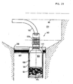
- a 'Gully detector 172 is in a manhole 171, which may be located in the floor of a nuclear power plant space, shown, which in the case of an inflow causes corresponding signals from emerging from a water leak within the monitoring device.
- the temperature-humidity measuring cable 101 is arranged on an insert body 173, which is located in the area of the gully 171.
- the insert body 173 in the present embodiment consists of a suitable plastic material and is tapered downwards.
- the insert body 173 has a slightly larger peripheral edge 174 which rests on the top of the container wall 175.
- a peripheral recess 176 is formed in the insert body 173, in which the temperature-humidity measuring cable 101 is mounted.
- a plug socket 177 is arranged closed in a moisture-tight manner.
- the plug socket 177 is held by radial support struts 178.
- the sensor cable 101 is led from the socket 177 through the support strut 178 upward into the region of the circumferential recess 176, in which it is positively mounted with two circumferential turns and from here is then returned through the support strut 178 to the socket 177.
- the arrangement of the sensor cable 101 has been made so that the diameter in the range of two turns of the sensor cable is slightly larger than the diameter of the insert body 173 underneath.
- the diameter in the area of the sensor cable turns is matched to the diameter of the container wall 175 in such a way that the temperature-humidity measuring cable 101 is tightly adjacent to the container wall 175 so that in the event of even a slight water access, the temperature-humidity measuring cable 101 is immediately taken, whereby not only a signal is given via the moisture display, but also a signal via the temperature display if the incoming leakage water is, for example, a slightly different temperature than that Ambient temperature.
- a plug 179 of a corresponding (4-pin) measuring line 180 is inserted into the plug socket 177 in a liquid-tight manner, but is nevertheless detachable and detachable at any time.
- the measuring line 180 runs under the gully cover 181 to the edge region of the gully 171 and is carried on from here for processing the measured values.
- the in the FIG. 23 drain detector 182 shown is also inserted into a drain 171 which is covered with a drain cover 181.
- the gully detector 182 also comprises a measuring line 180 with a plug 179 which is inserted in a liquid-tight manner into a plug socket 177 of an insert body 183.
- the plug socket 177 is mounted absolutely tight in the insert body 183.
- the temperature-humidity measuring cable 101 runs from the plug socket 177 inside the insert body 183 to the outside and is preferably positively supported in 4 turns in a circumferential recess 184 of the insert body 183 and from there is returned to the socket 177.
- the insert body 183 which, like the insert body 173 described above, with the plug socket 177 and the temperature-humidity measuring cable 101, is designed as an essentially one-piece and easy-to-use structural unit, is located in a tubular container part 185, which is in the region of a ring 186 is attached off-center to the inside edge.
- the ring 186 has an O-ring 187, which is mounted in a circumferential groove and lies sealingly against the gully wall.
- a trough-shaped liquid supply is formed, so that any leakage water at this point initially enters the container part 185 in a forced manner, whereby due to the practically play-free arrangement of the temperature-moisture measuring cable 101 in the region of the container wall 188 immediate signaling via the moisture measuring part and / or the temperature measuring part takes place.
- FIG. 24 shows a diagram for gully monitoring according to the invention with the following functions: test inputs 189, setpoint constant current source 190, measuring range resistor 191, humidity / temperature sensor 192, range shift 193 for base load resistance, encoder break output 194 and limit value output 195.
- the measured value acquisition of the gully monitoring device thus includes, like the Daqfrohr monitoring device, a moisture detector with an integrated temperature sensor, wherein the temperature sensor, designed as a resistance wire, can also be used as a heating element for the sensor cable drying in the area of the gully detector if the voltage is applied accordingly.
- the detection system is absolute potential free.
- the moisture detector contains the copper wires with variable base load resistance for sensitivity and wire break monitoring.
- the insulation consists of multi-layer wrapped glass fabric. All measuring cables commonly used in MCR technology can be connected. The maximum cable length is approx. 3000 m. Depending on the basic sensor resistance, measuring ranges between 1-20 M-Ohm can be set.
- the limit value output voltage is preferably greater than 200 mV.
- the response speed is less than 1 sec with a measuring range of 10 M-Ohm-0.
- the interference suppression is greater than 70 dB at 50 Hz.
- the measured value processing is carried out essentially advantageously as in the case of the steam pipe monitoring device described above and can be a transmitter, evaluation electronics, control systems, alarm devices and the like. Like. Include.
- the sensor cable 1, 101, 111 according to the invention can also be used particularly advantageously in the context of the invention on a non-insulated pipe, a container or the like for detecting any changes in temperature and / or humidity. It is possible to lay the temperature-humidity measuring cable 1, 101, 111 coaxially along the outside of the pipe wall, for example, and to fasten it by means of clamps, bands or the like.
- the measuring cable 1, 101, 111 can also be wound, for example, in a spiral around the pipe or the object to be monitored, such as a valve, pressure compensation unit, pressure gauge or the like.
Abstract
Description
Die Erfindung betrifft eine Überwachungseinrichtung mit den Merkmalen des Oberbegriffs des Anspruchs 1.The invention relates to a monitoring device with the features of the preamble of
Zur Überwachung von Dampfrohren od. dgl. in Kraftwerken, insbesondere Kernkraftwerken, ist es bekannt, sowohl Temperaturänderungen als auch Feuchtigkeitsänderungen zu überwachen, um beim Überschreiten eines Schwellwertes im Falle einer etwaigen Leckage an Systemteilen umgehend entsprechende Maßnahmen zur Schadensbehebung und Unfallverhütung einleiten zu können. Dazu ist es bekannt, etwaige Temperaturänderungen über einen Widerstandsdraht zu erfassen und Feuchtigkeitsschwankungen über einen hygroskopischen Isolator aufzunehmen, wobei durch einen unterschiedlichen Feuchtigkeitsgehalt entsprechende Widerstands- und/oder Kapazitätsänderungen erfasst werden können. Diese ansieh zuverlässige sowie funktionstüchtige Meß- bzw. Überwachungsmethode der beiden Faktoren Temperatur und Feuchtigkeit ist insofern nicht ganz zufriedenstellend, da die Herstellung und Anordnung des Meßsystems verhältnismäßig aufwendig ist. Dies insbesondere deshalb, weil für die Temperaturerfassung und für die Feuchtigkeitserfassung praktisch verschiedene und im wesentlichen getrennt voneinander angeordnete Erfassungssysteme angewandtwerden. Das heißt, daß ein verhältnismäßig großer mechanischer Aufwand bei der Herstellung zu bewältigen ist, da eine Reihe verschiedener Bauteile zueinander in Verbindung gebracht werden müssen, was sich zudem auch nicht unwesentlich nachteilig auf die Herstellungskosten auswirken kann, da die Einzelbauteile teuer und die Montagearbeiten zeitaufwendig sind. Weiterhin ist ein verhältnismäßig großer Platzbedarf für die Meßanrodnung erforderlich. Außerdem ist die Lebensdauer bzw. Funktionstüchtigkeit eingeschränkt, da aufgrund der vielfältigen Bauteile eine entsprechend große Gefahr für ein Versagen bzw. einen Ausfall eines Teils gegeben ist. Darüber hinaus beinhaltet das bisherige Meßsystem eine Störempfindlichkeit, die eine genaue Überwachung beeinträchtigen kann.In order to monitor steam pipes or the like in power plants, in particular nuclear power plants, it is known to monitor both temperature changes and moisture changes in order to be able to immediately initiate appropriate measures for damage repair and accident prevention if a threshold value is exceeded in the event of any leakage in system parts. For this purpose, it is known to record any temperature changes via a resistance wire and to record moisture fluctuations via a hygroscopic insulator, wherein changes in resistance and / or capacitance can be recorded by a different moisture content. This reliable and functional measuring and monitoring method of the two factors of temperature and humidity is not entirely satisfactory insofar as the manufacture and arrangement of the measuring system is relatively complex. This is particularly so because practically different and essentially separate detection systems are used for temperature detection and for moisture detection. This means that a relatively large mechanical effort has to be mastered in the production, since a number of different components have to be connected to one another, which can also have a not inconsiderable disadvantage on the production costs, since the individual components are expensive and the assembly work is time-consuming. Furthermore, a relatively large amount of space is required for the measuring arrangement. In addition, the service life or functionality is limited, since the diverse components pose a correspondingly great risk of failure or failure of a part. In addition, the previous measuring system includes a sensitivity to interference, which can impair accurate monitoring.
Demgemäß besteht die Aufgabe der Erfindung darin, eine Überwachungseinrichtung der eingangs beschriebenen Art so zu verbessern, daß eine wesentliche Einsparung verschiedener Bauteile, eine Platzersparnis sowie eine höhe» Funktionstüchtigkeit erreicht werden kann.Accordingly, the object of the invention is to improve a monitoring device of the type described in the introduction in such a way that a substantial saving in various components, a space saving and a high degree of functionality can be achieved.
Diese Aufgabe wird erfindungsgemäß durch die Kennzeichnungsmerkmale des Anspruchs 1 gelöst.This object is achieved by the characterizing features of
Ein mit der Erfindung erzielter Vorteil besteht darin, daß die Temperatur- und Feuchtigkeitsüberwachung über ein baueinheitlich kombiniertes Temperatur-Feuchte-Meßkabel durchgeführt werden kann, wobei ausschließlich zwei Drähte mit einem zwischen diesen angeordneten hygroskopischen Isolator sowohl für die Erfassung einer Feuchteänderung als auch einer Temperaturänderung erforderlich sind,so daß ein denkbar einfaches Sensorkabel für gleichzeitig mehrere Meßfunktionen gegeben ist. Das erfindungsgemäße Temperatur-Feuchte-Meßkabel ist äußerst kostengünstig herstellbar und besitzt eine hohe Lebensdauer, da die zum Einsatz gelangenden Teile auf ein Minimum reduziert sind. Außerdem ist das Temperatur- Feuchte-Meßkabel sehr schmal und benötigt bei der Montage am Dampfrohr einen vernachlässigbar geringen Platzbedarf, so daß stets eine.den jeweiligen Erfordernissen angepaßte Montagepositionierung durchgeführt werden kann. Das erfindungsgemäße Temperatur-Feuchte-Meßkabel ermöglicht eine im wesentlichen störfreie kontinuierliche Überwachung auch über größere Entfernungen. Darüber hinaus eignet sich das Temperatur-Feuchte-Meßkabel insbesondere auch für eine äußerst hohe Meßempfindlichkeit, so daß etwaige Leckstellen bereits im geringsten Ansatz frühzeitig erkannt werden können, Da das Temperatur- Feuchte-Meßkabel als baueinheitlicher Mehrfunktionsstrang ausgebildet ist, ist eine absolute Wartungsfreiheit gegeben, da keinerlei Einzelbauteile nachzujustieren oder auszutauschen sind. Tritt im Falle einer Leckage Dampf aus der Wandung des Dampfrohres aus, so erfolgt eine Temperaturänderung, die vom Widerstandsdraht unmittelbar erfaßt wird. Gleichzeitig erfolgt eine Feuchtigkeitsanreicherung im Hygroskopisolator. Diese Feuchtigkeits- änderung im Hygroskopisolator zwischen dem Widerstandsdraht und dem Leiterdraht wird ebenfalls unmittelbar aufgrund der damit verbundenen Widerstands- bzw. Kapazitätsänderung erfaßt-bzw. aufgenommen. Aufgrund der Messung der beiden unterschiedlichen Faktoren Temperatur und Feuchte ist eine hohe Sicherheit für eine zuverlässige Überwachung und Warnauslösung gegeben, da letztere ohne weiteres so konzipiert sein kann, daß ein Ansprechen ausschließlich bei einer Änderung beider Meßfaktoren ausgelöst wird.An advantage achieved with the invention is that the temperature and humidity monitoring can be carried out via a modularly combined temperature-humidity measuring cable, only two wires with a hygroscopic insulator arranged between them being necessary both for the detection of a change in humidity and a change in temperature are, so that a very simple sensor cable is given for several measurement functions at the same time. The temperature-humidity measuring cable according to the invention is extremely inexpensive to manufacture and has a long service life because the parts used are open are reduced to a minimum. In addition, the temperature-humidity measuring cable is very narrow and requires a negligible amount of space when mounting on the steam pipe, so that a mounting position adapted to the respective requirements can always be carried out. The temperature-humidity measuring cable according to the invention enables essentially trouble-free continuous monitoring even over greater distances. In addition, the temperature-humidity measuring cable is particularly suitable for an extremely high measuring sensitivity, so that any leaks can be detected early, even in the slightest approach. Since the temperature-humidity measuring cable is designed as a multi-function line, there is absolutely no maintenance. since no individual components need to be readjusted or replaced. If steam escapes from the wall of the steam pipe in the event of a leak, a temperature change takes place which is immediately detected by the resistance wire. At the same time, moisture accumulation takes place in the hygroscope isolator. This change in moisture in the hygroscope insulator between the resistance wire and the conductor wire is also detected or due to the associated change in resistance or capacitance. added. Due to the measurement of the two different factors, temperature and humidity, there is a high level of security for reliable monitoring and triggering of warnings, since the latter can easily be designed in such a way that a response is triggered only when both measurement factors change.
Bevorzugte Ausgestaltungen und Weiterbildungen der Erfindung sind den Merkmalen der Unteransprüche, der Beschreibung und der Zeichnung zu entnehmen, wonach es vorteilhaft sein kann, das Temperatur-Feuchte-Meßkabel als Kabelschleife auszuführen und mit einem Steckerteil zu versehen, der zwei dem Widerstandsdraht zugeordnete Anschlußpole und mindestens einen Polanschluß für den Leiterdraht besitzt. Zweckmäßig können jedoch zwei Polanschlüsse für den Leiterdraht vorgesehen sein, wodurch bei der Feuchteüberwaohung gleichzeitig eine Drahtbruchüberwachung möglich ist.Preferred refinements and developments of the invention can be found in the features of the subclaims, the description and the drawing, according to which It may be advantageous to design the temperature-humidity measuring cable as a cable loop and to provide it with a plug part which has two connecting poles assigned to the resistance wire and at least one pole connection for the conductor wire. However, two pole connections can expediently be provided for the conductor wire, as a result of which wire break monitoring is possible at the same time during the monitoring of moisture.
Der Leiterdraht des Temperatur-Feuchte-Meßkabels kann vorteilhaft aus einer aus Einzeldrähten gebildeten Litze bestehen, wodurch eine hohe Flexibilität erreicht werden kann und zudem eine Bruchgefahr des Leiterdrahtes weitgehend ausgeschaltet ist. Der Hygroskopisolator kann zweckmäßig als den Leiterdraht umgebende Hülle ausgeführt sein und kann zwecks hoher Beständigkeit gegen äußere Einflüsse, insbeondere auch radioaktive Strahlung, aus einem mineralischen Stoff bestehen, wobei eine Glasseidenisolation aus fertigungs- und anwendungstechnischen Gründen besonders vorteilhaft sein kann. Die Glasseidenisolation kann als Gewebeschlauch, Geflecht oder Gespinst ausgeführt sein. Auch ist es möglich, den Hygroskopisolator: zum Beispiel aus feuchtigkeitsaufnehmendem Zellstoff, aus Papierlagen od, dgl. herzustellen, wobei jedoch mineralische Stoffe wie Keramik oder Glas nicht nur den Vorteil einer höheren mechanischen Festigkeit sondern auch gerade eine hohe Strahlungsbeständigkeit besitzen, so daß auch bei einer Dauerstrahlungsbeanspruchung eine hohe Lebensdauer gegeben ist, weshalb das erfindungsgemäße Temperatur-Feuchte-Meßkabel auch bevorzugt im Kernkraftsektor zur Überwachung entsprechender Leitungssysteme und dgl. eingesetzt werden kann.The conductor wire of the temperature-humidity measuring cable can advantageously consist of a strand formed from individual wires, as a result of which a high degree of flexibility can be achieved and, moreover, the risk of breakage of the conductor wire is largely eliminated. The hygroscope insulator can expediently be designed as a sheath surrounding the conductor wire and, for high resistance to external influences, in particular also radioactive radiation, can consist of a mineral substance, with fiberglass insulation being particularly advantageous for production and application reasons. The glass silk insulation can be designed as a fabric tube, braid or web. It is also possible to Hy g rosko p iso l ator., For example, moisture absorbent pulp, od of paper layers, like produce, but mineral materials such as ceramic or glass not only the advantage of a higher mechanical strength but also just a high radiation resistance have, so that even with continuous radiation exposure there is a long service life, which is why the temperature-humidity measuring cable according to the invention can also preferably be used in the nuclear power sector for monitoring corresponding line systems and the like.
Die Stärke des Hygroskopisolators kann etwa im Bereich zwischen 0,01 bis 1mm liegen. Vorzugsweise wird die Stärke des Hygroskopisolators jedoch etwa 0,1 bis 0,4 mm betragen, da hierbei zum einen ein praxisgerechter Isolationsabstand gegeben ist und zum andern eine hohe Meßempfindlichkeit vorliegt, die eine genaue Überwachung möglich macht. Der Widerstandsdraht des Temperatur-Feuchte-Meßkabela kann vorteilhaft in Form einer Schraubspirale um den den Leiterdraht umhüllenden Hygroskopisolator gewendelt sein. Der Abstand zwischen den Wendeln kann etwa im Bereich zwischen 0,3 bis 10 mm liegen, wobei ein den praktischen Erfordernissen erforderlicher günstiger Abstand etwa 0,5 bis 4 mm sein kann. Durch eine solche Wendelausführung kann bei entsprechender Abstandsänderung der Widerstand variiert bzw. genau angepaßt werden. Zudem wird dadurch eine gewisse Eigensteifigkeit des flexiblen Temperatur-Feuchte-Meßkabels erreicht, wodurch eine bessere Handhabung während der Montage möglich ist, da eine etwaige/störende Lappigkeit des Kabels vermieden ist.The strength of the hygroscope isolator can be in the range between 0.01 and 1mm. However, the thickness of the hygroscope isolator is preferably approximately 0.1 to 0.4 mm, since on the one hand there is a practical insulation spacing and on the other hand there is a high measurement sensitivity, which enables precise monitoring. The resistance wire of the temperature-humidity measuring cable can advantageously be wound in the form of a screw spiral around the hygroscope insulator encasing the conductor wire. The distance between the coils can be approximately in the range between 0.3 to 10 mm, and a favorable distance required for practical requirements can be approximately 0.5 to 4 mm. With such a helical design, the resistance can be varied or precisely adapted with a corresponding change in distance. In addition, a certain intrinsic stiffness of the flexible temperature-humidity measuring cable is achieved, which enables better handling during assembly, since a possible / troublesome lumpiness of the cable is avoided.
Weiterhin kann es insbesondere vorteilhaft sein, das erfindungsgemäße Temperatur-Feuchte-Meßkabel mit einem feuchtigkeitsdurchlässigen Außenmantel zu versehen, der den Leiterdraht, den Hygroskopisolator und den Widerstandsdraht formschlüssig umhüllt. Zweckmäßig kann ein solcher Außenmantel ebenfalls aus einem mineralischen Stoff bestehen und vorteilhaft als Glasseidengewebeschlauch ausgeführt sein. Ein derartiger Außenmantel bewirkt zum einen eine Festigkeitserhöhung gegen äußere mechanische Beanspruchungen, so daß auch ein Einsatz unter rauhen Betriebsbedingungen ohne weiteres möglich ist. Der zweckmäßig als flexibles Gewebe bzw. Gespinst ausgeführte schlauchförmige Außenmantel bewirkt zudem eine Potentialfreiheit, so daß praktisch keine Störungen durch Fremdspannungen, Übergangswiderstände od. dgl. das Meßsystem beeinträchtigen können.Furthermore, it can be particularly advantageous to provide the temperature-humidity measuring cable according to the invention with a moisture-permeable outer sheath, which envelops the conductor wire, the hygroscope insulator and the resistance wire in a form-fitting manner. Such an outer jacket can expediently also consist of a mineral material and advantageously be designed as a glass silk fabric hose. Such an outer jacket firstly increases the strength against external mechanical stresses, so that use under rough operating conditions is also readily possible. The tubular outer sheath, which is expediently designed as a flexible fabric or web, also provides freedom from potential, so that there are practically no interferences from outside voltages, contact resistances or the like. can impair the measuring system.
Dem erfindungsgemäßen Temperatur-Feuchte-Meßkabel wird bei der Überwachung eines Rohrleitungssystems od. dgl. zweckmäßig ein elektronischer Auswerteteil zugeordnet, der einen Temperaturmeßteil und einen Feuchtemeßteil besitzt. Weiterhin kann ein Anzeigeteil für einen etwaigen Leiterdrahtbruch der Feuchtemessung vorgesehen sein und es ist zudem möglich, einen eventuellen Widerstandsdrahtbruch ebenfalls anzuzeigen, so daß eine feuehtigkei ts-und temperaturerfassende Leckageüberwachung und eine Eigenüberwachung des Meßsystems bezüglich seiner Funktionsfähigkeit erzielt werden kann. Vorteilhaft können bei der erfindungsgemäßen Überwachungseinrichtung zwei Enden des dem Temperatur-Feuchte-Meßkabel zugehörigen Widerstandsdrahtes dem Temperaturmeßteil und zwei Enden des Leiterdrahtes dem Leiterdrahtbruchanzeigeteil im elektronischen Auswerteteil zugeordnet sein. Dem Feuchtemeßteil des elektronischen Auswerteteils wird hierbei zweckmäßig ein Leitungsteil des Leiterdrahtes und eine Teilleitung des Widerstandsdrahtes des Temperatur- Feuchte-Meßkabels im Bereich des Auswerteteils zugeführt.When monitoring a pipeline system or the like, an electronic evaluation part is expediently assigned to the temperature-moisture measuring cable according to the invention, which has a temperature measuring part and a moisture measuring part. Furthermore, a display part for a possible wire break of the moisture measurement can be provided and it is also possible to also indicate a possible wire break, so that leakage and temperature-detecting leakage monitoring and self-monitoring of the measuring system with regard to its functionality can be achieved. In the monitoring device according to the invention, two ends of the resistance wire associated with the temperature-humidity measuring cable can advantageously be assigned to the temperature measuring part and two ends of the conductor wire to the conductor wire breakage display part in the electronic evaluation part. A line part of the conductor wire and a part line of the resistance wire of the temperature-humidity measuring cable in the region of the evaluation part are expediently fed to the moisture measuring part of the electronic evaluation part.
Zur Überwachung kann es günstig sein, das erfindungsgemäße Temperatur-Feuchte-Meßkabel im Bereich einer 'das Dampfrohr od. dgl. umgebenden Wärmeisolierung anzuordnen. Hierbei kann es zweckmäßig sein, die Anordnung so zu treffen, daß das Temperatur-Feuchte-Meßkabel dicht an einer Innenseite einer Umhüllung zu liegen kommt, die die Wärmeisolierung umfaßt. Ein sich in diesem Bereich bildendes Kondensat eines eventuell austretenden Dampfes wird hier vom hygroskopischen Feuchtefühler unmittelbar erfaßt. Ebenso wird eine dabei auftretende Temperaturänderung vom Temperatur-Feuchte-Meßkabel umgehend erfaßt. Das Temperatur-Feuchte-Meßkabel kann vorteilhaft in Längsrichtung des Dampfrohres od. dgl. angeordnet sein, wodurch eine lineare Streckenüberwachung möglich ist. Dabei können auch mehrere Temperatur-Feuchte-Meßkabel auf Abstand parallel nebeneinander vorgesehen werden. Zweckmäßig kann das Temperatur-Feuchte-Meßkabel im Bereich der Wärmeisolierung in einer Nut angeordnet werden, wobei die Nut nach außen durch einen im wesentlichen als Streifen ausgeführten Abdeckteil verschlossen sein kann, so daß das Meßkabel gegen Außeneinflüsse sicher abgeschirmt ist. Darüber hinaus ist es möglich, das Temperatur-Feuchte-Meßkabel praktisch ringförmig um das Dampfrohr anzuordnen und hierbei in einer entsprechenden Umfangsnut zu lagern. Dies kann zum Beispiel im Bereich von Isolationsstoßstellen und auch Rohranschlußstellen günstig sein.For monitoring, it can be favorable to arrange the temperature-humidity measuring cable according to the invention in the area of a heat insulation surrounding the steam pipe or the like. In this case, it may be expedient to make the arrangement in such a way that the temperature-humidity measuring cable comes to lie close to an inner side of a covering which comprises the thermal insulation. A condensate of a possibly escaping steam that forms in this area is here from the hygroscopic moisture sensor indirectly recorded. Likewise, any temperature change that occurs is immediately detected by the temperature-humidity measuring cable. The temperature-humidity measuring cable can advantageously be arranged in the longitudinal direction of the steam pipe or the like, as a result of which linear path monitoring is possible. It is also possible to provide several temperature-humidity measuring cables parallel to one another at a distance. The temperature-humidity measuring cable can expediently be arranged in a groove in the area of the thermal insulation, the groove being able to be closed to the outside by a cover part which is essentially designed as a strip, so that the measuring cable is reliably shielded from external influences. In addition, it is possible to arrange the temperature-humidity measuring cable practically in a ring around the steam pipe and to store it in a corresponding circumferential groove. This can be beneficial, for example, in the area of insulation joints and pipe connection points.
Weiterhin kann es zur Erzielung störfreier Feuchte-und Temperaturmessungen besonders vorteilhaft sein, den Leiterdraht im Temperatur-Feuchte-Meßkabel so auszubilden, daß er aus zwei getrennten Drahtleitersträngen besteht. Die beiden Drahtleiterstränge können parallel zueinander verlaufen. Zwischen ihnen befindet sich der Hygroskopisolator. Die Feuchtigkeitsmessung erfolgt hierbei ausschlielich über die beiden Drahtleiterstränge, so daß beide Meßsysteme so voneinander getrennt sind, daß sie sich nicht gegenseitig beeinflussen können. Es ist damit ein einfaches Sensorkabel für mehrere Meßfunktionen gegeben, welches zuverlässig potentialfreie Messungen gewährleistet.Furthermore, in order to achieve interference-free moisture and temperature measurements, it can be particularly advantageous to design the conductor wire in the temperature-moisture measuring cable such that it consists of two separate wire conductor strands. The two wire conductor strands can run parallel to one another. The hygroscope isolator is located between them. The moisture measurement takes place exclusively via the two wire conductor strands, so that the two measuring systems are so separated from one another that they cannot influence one another. It is one simple sensor cable for several measuring functions, which reliably ensures potential-free measurements.
Die Drahtleiterstränge im Temperatur-Feuchte-Meßkabel sind zweckmäßig als Litzenausgeführt, die aus dünnen Kupferdrähten gebildet sind, so daß eine praktikable Flexibilität erzielt wird. Der Hygroskopisolator kann vorteilhaft als Hülle in Form eines gewebten bzw. geflochtenen Glasseidenisolationsschlauches ausgeführt sein, wobei es günstig ist, jeden einzelnen Drahtleiterstrang mit je einer Glasseidenhülle zu umgeben. Weiterhin können auch die beiden Drahtleiterstränge mit ihrem Hygroskopisolator von einem weiteren feuchtigkeitsdurchlässigen Isolator umgeben sein, welcher ebenfalls ein aus Glasseide bestehender Gewebeschlauch sein kann, in dem die Drahtleiterstränge zusammengefaßt sind. Auf diesem die Drahtleiterstränge zusammenfassenden Isolator kann vorteilhaft der Widerstandsdraht des Temperatur-Feuchte-Meßkabels angebracht sein, wobei es günstig ist, diesen Widerstandsdraht spiral- bzw, wendelförmig gewickelt auf dem Isolator anzuordnen. Zur Erzielung eines äußeren Gesamtabschlusses kann das Temperatur-Feuchte-Meßkabel eine Außenhülle besitzen, die feuchtigkeitsdurchlässig ist und zweckmäßig auch als geflochtener bzw. gewebter Glasseidenschlauch ausgeführt ist. Die vorbeschriebenen verschiedenen Glasseidenisolationen bewirken nicht nur eine hohe Festigkeit gegen äußere mechanische Beanspruchungen, sondern sind zudem weitgehend resistent gegenüber anderweitigen Materialien und gewährleisten zudem eine hohe Temperaturfestigkeit im Dauereinsatz.The wire conductor strands in the temperature-humidity measuring cable are expediently designed as strands which are formed from thin copper wires, so that practical flexibility is achieved. The hygroscope insulator can advantageously be designed as a sheath in the form of a woven or braided glass silk insulation tube, it being favorable to surround each individual wire conductor strand with a glass silk sheath. Furthermore, the two wire conductor strands with their hygroscopic insulator can also be surrounded by another moisture-permeable insulator, which can also be a fabric tube made of glass silk, in which the wire conductor strands are combined. The resistance wire of the temperature-humidity measuring cable can advantageously be attached to this insulator which summarizes the wire conductor strands, it being favorable to arrange this resistance wire on the insulator in a spiral or helically wound manner. In order to achieve an overall outer closure, the temperature-humidity measuring cable can have an outer sheath which is permeable to moisture and is also expediently designed as a braided or woven glass silk tube. The various glass fiber insulations described above not only result in high strength against external mechanical stresses, but are also largely resistant to other materials and also ensure high temperature resistance in continuous use.
Um die Empfindlichkeit des Feuchtemeßsystems weitgehend beeinflussen bzw. den Erfordernissen entsprechend anpassen zu können, ist es günstig, dem Leiterdraht bzw. den beiden Drahtleitersträngen einen sogenannten Grundlastwiderstand zuzuordnen, der sowohl für die Feuchte- - detektion als auch zum Zwecke einer Drahtbruchüberwachung nützlich ist, wobei der Grundlastwiderstand zwischen den beiden Drahtleitersträngen bevorzugt an dem Ende des Temperatur-Feuchte-Meßkabels vorgesehen werden kann, welches vom Anschluß zumindest elektrisch gesehen entfernt liegt. Für den Anschluß des Temperatur-Feuchte-Meßkabels kann eine vorzugsweise 4-polige Steckerbuchse vorgesehen sein, in die ein entsprechender Stecker einer Meßleitung vorzugsweise feuchtigkeits- und staubdicht eingesteckt werden kann. Darüber hinaus kann es günstig sein, einen Rückführleiter für den Widerstandsdraht vorzusehen, welcher bevorzugt durch eine Löt- oder Schweißverbindung mit dem Ende des Widerstandsdrahtes verbunden wird. Der Rückführleiter besitzt zweckmäßig eine temperaturbeständige Isolation, die zum Beispiel aus Teflon oder auch aus Glasseide bestehen kann. Bei dieser Ausführung wird für die Temperaturmessung der Widerstand bzw. die Widerstandsänderung zwischen dem Anfang des Widerstandsdrahtes und dessen Ende erfaßt, wobei die Zurückführung von dem dem Anschluß des Temperatur-Feuchte-Meßkabels entfernt-liegenden äußersten Ende durch den Rückfuhrleiter erfolgt. Der Rückführleiter kann außen am Temperatur-Feuchte-Meßkabel liegen und an letzterem zum Beispiel mittels elastischen bzw. gummiähnlichen Halteringen befestigt sein. Der Rückführleiter besteht vorwiegend aus einer Kupferlitze, die auch innerhalb der Außenhülle des Temperatur- Feuchte-Meßkabels im wesentlichen parallel zu den Drahtleitersträngen verlaufen kann, wobei der Rückführleiter sowohl im Bereich zwischen dem Widerstandsdraht und der Außenhülle als auch im Bereich unmittelbar neben den Drahtleitersträngen liegen kann. Auch ist es möglich, den Rückführleiter des Widerstandsdrahtes zum Beispiel aus dünnen Kupferdrähten als Flechtschlauchhülle auszuführen. In der einfachsten Anwendungsform kann das Temperatur-Feuchte-Meßkabel zum Beispiel im Bereich einer insbesondere gestopften Wärmeisolation unbeschränkt frei verlegt werden, derart, daß es sich sowohl in Längsrichtung als auch in Umfangsrichtung des Dampfrohres bzw. des Behälters oder dergleichen erstreckt. Eine bevorzugte Lage wird im Bereich zwischen der Wandung des Dampfrohres und äußeren Umhüllung der Wärmeisolation nahe der Innenfläche der Umhüllung gesehen, wobei allerdings wie bereits ausgeführt hier grundsätzlich keine Einschränkungen gegeben sind, so daß entsprechend den örtlichen Erfordernissen jeweils eine optimale Installation des Temperatur- Feuchte-Meßkabels für eine einwandfreie Leckagedetektion ausgeführt werden kann.To the sensitivity of the moisture measurement system largely influence or adapt it to the requirements, it is favorable to assign a so-called base load resistance to the conductor wire or the two wire conductor strands, which is useful both for moisture detection and for the purpose of wire break monitoring, the base load resistance between the two wire conductor strands can preferably be provided at the end of the temperature-humidity measuring cable, which is at least electrically seen from the connection. For the connection of the temperature-humidity measuring cable, a preferably 4-pin plug socket can be provided, into which a corresponding plug of a measuring line can be inserted, preferably in a moisture and dust-tight manner. In addition, it can be advantageous to provide a return conductor for the resistance wire, which is preferably connected to the end of the resistance wire by a soldered or welded connection. The return conductor expediently has temperature-resistant insulation, which can be made of Teflon or glass fiber, for example. In this embodiment, the resistance or the change in resistance between the beginning of the resistance wire and the end thereof is detected for the temperature measurement, the return being carried out by the return conductor from the outermost end remote from the connection of the temperature-humidity measuring cable. The return conductor can be on the outside of the temperature-humidity measuring cable and can be attached to the latter, for example, by means of elastic or rubber-like retaining rings. The return conductor consists predominantly of a copper strand, which can also run essentially parallel to the wire conductor strands within the outer sheath of the temperature-humidity measuring cable, the return conductor both in the area between the resistance wire and the outer sheath and in the area directly can lie next to the wire conductor strands. It is also possible to design the return conductor of the resistance wire, for example, from thin copper wires as a braided sleeve. In the simplest form of application, the temperature-humidity measuring cable can be laid freely, for example in the area of a particularly stuffed thermal insulation, in such a way that it extends both in the longitudinal direction and in the circumferential direction of the steam pipe or the container or the like. A preferred position is seen in the area between the wall of the steam pipe and the outer covering of the thermal insulation near the inner surface of the covering, although as already stated there are basically no restrictions here, so that an optimal installation of the temperature-humidity in each case according to the local requirements. Measuring cable can be carried out for a perfect leak detection.
Weiterhin kann es insbesondere vorteilhaft sein, das Temperatur-Feuchte-Meßkabel an einem Flachband anzuordnen, welches insofern flexibel ist, daß es zum Beispiel wie ein Spannband um ein Rohr bzw. dessen Wärmeisolation geschlungen werden kann. Das Flachband kann in hochwertiger Ausführung aus einem rostfreien und antimagnetischen Edelstahl bestehen und es kann einen Spannverschluß besitzen, der im wesentlichen feinstufig nachstellbar ist, so daß bei der Montage am Dampfrohr etwaige Toleranzen im Bereich der Wärmeisolierung problemlos ausgeglichen werden können, wodurch in jedem Falle ein einwandfreier Sitz des Spannbandes und damit auch des Temperatur-Feuchte-Meßkabels sichergestellt ist. Die Befestigung des Temperatur-Feuchte-Meßkabels kann vorteilhaft über einen Spannklotz erfolgen, der zum Beispiel aus einem elastischen und temperaturbeständigen Silikonkautschuk hergestellt und mit einem Klemmbügel am Flachband befestigt ist. Der Spannklotz kann an der dem Flachband zugewandten Seite eine oder auch zwei Längsnuten besitzen, in denen das Temperatur-Feuchte-Meßkabel gelagert und geführt ist, wobei bei einem schleifenförmig am Flachband angeordneten Temperatur-Feuchte-Meßkabel in der einen Längsnut der Vorführkabelteil und in der anderen Längsnut der Rückführkabelteil des Temperatur-Feuchte-Meßkabels sich befindet. Zur Gewährleistung einer Potentialfreiheit auch gegenüber etwaigen äußeren Einflüssen kann zwischen dem Spannklotz und dem Flachband eine Isolierfolie vorgesehen sein, so daß die Außenhülle des Temperatur-Feuchte-Meßkabels im Bereich des Spannklotzes selbst bei einer Druckbeanspruchung nicht in eine unmittelbare Berührung mit dem Flachband gelangt. Die Isolierfolie kann aus Kapton oder dergleichen bestehen. Der Klemmbügel für den Spannklotz kann mittels Schrauben lösbar am Spannband befestigt sein. Es ist aber auch möglich, den Klemmbügel mittels Nieten oder durch Punktschweißen zu befestigen. Der Klemmbügel kann an beiden Seiten Begrenzungsstege aufweisen, deren freie Enden für ein problemloses Einstecken in eine Nut vorteilhaft schräg abgebogen bzw. gerundet sind. Die Spannklötze und Klemmbügel können etwa in fünfzehn Zentimeterabständen zueinander in Längsrichtung des Flachbandes in dessen Mittenbereich angeordnet sein. Ist das Temperatur- Feuchte-Meßkabel hierbei als Kabelschleife mit einem Vorführkabelteil und einem Rückführkabelteil ausgeführt, so ist es zur Vermeidung von seitlichen Kabelausbiegungen günstig, den Vorführkabelteil und den Rückführkabelteil jeweils zwischen zwei Spannklötzen so anzuordnen, daß sie sich kreuzen. Wird das Flachband mit dem so angeordneten Temperatur-Feuchte-Meßkabel ringförmig um eine Wärmeisolation gelegt, so wölben sich die Kabelteile zwischen den Spannklötzen nicht zur Seite aus, sondern verlaufen weiterhin im wesentlichen in ihrer vorgegebenen Längsrichtung, so daß Temperatur-Feuchte-Meßkabel sicher in den Bereich der Nut in der Wärmeisolation gelangt und nicht zwisehen deren äußerer Umhüllung und dem Spannband eingeklemmt wird. Vorteilhaft kann das Flachband mit dem Sensorkabel im Bereich einer Stoßstelle der Wärmeisolierung, die zum Beispiel als Kassettenisolation ausgeführt sein kann, angeordnet werden. Das Flachband überdeckt dabei eine Nut, die sich im oberen Bereich der Wärmeisolierung an die Stoßstelle anschließt. Das Meßkabel gelangt dabei in den Bereich der Nut, wobei die Klemmbügel mit ihren seitlichen Begrenzungsstegen nahe den Seitenwandungen der Nut verlaufen, so daß eine Sicherung gegen ein seitliches Verschieben des Flachbandes gewährleistet ist. Der Anschluß des Temperatur-Feuchte-Meßkabels kann im Bereich der Steckerbuchse, die vorteilhaft im Bereich eines Lochs am Flachband befestigt bzw, festgeschraubt ist, in einem Anschlußblock abgedichtet sein. Dieser Anschlußblock besteht vorzugsweise aus einem feuchtigkeitsdichten und elektrisch isolierenden Gießharz und ist vorteilhaft so gestaltet und angeordnet, daß er in Längsrichtung des Flachbandes im wesentlichen in einer Ebene mit dem Spannklotz bzw. den Klemmbügeln liegt und zudem etwa die gleiche Breite wie der Klemmbügel besitzt, so daß beim Festspannen des Flachbandes der Anschlußblock ebenfalls zentrierend in die Nut eingreift und somit zur Sicherung gegen eine etwaige Seitenverschiebung beiträgt.Furthermore, it can be particularly advantageous to arrange the temperature-humidity measuring cable on a flat band, which is flexible in that it can be looped around a pipe or its thermal insulation, for example, like a tension band. The flat tape can consist of a high quality version made of a rustproof and antimagnetic stainless steel and it can have a tension lock which can be adjusted essentially in fine steps, so that any tolerances in the area of thermal insulation can be easily compensated for during installation on the steam pipe, whereby in any case one a perfect fit of the tensioning strap and thus of the temperature-humidity measuring cable is ensured. The temperature-humidity measuring cable can advantageously be attached via a clamping block, which, for example, consists of a elastic and temperature-resistant silicone rubber is manufactured and attached to the ribbon with a clamp. The clamping block may have one or even two longitudinal grooves in which the temperature-humidity at the side facing the flat side - is mounted measuring cable and is guided, wherein, in a loop-shaped arrangement of the flat strip temperature-humidity-measuring cable in a longitudinal groove of the Vorführkabelteil and in the other longitudinal groove of the return cable part of the temperature-humidity measuring cable is. In order to ensure freedom from potential also against any external influences, an insulating film can be provided between the tensioning block and the flat strip, so that the outer sheath of the temperature-moisture measuring cable in the area of the tensioning block does not come into direct contact with the flat strip even when subjected to pressure. The insulating film can consist of Kapton or the like. The clamping bracket for the clamping block can be detachably fastened to the clamping band by means of screws. However, it is also possible to fasten the clamping bracket using rivets or spot welding. The clamping bracket can have limiting webs on both sides, the free ends of which are advantageously bent or rounded obliquely for problem-free insertion into a groove. The tensioning blocks and clamping brackets can be arranged approximately at fifteen centimeters from one another in the longitudinal direction of the flat strip in the central region thereof. If the temperature-humidity measuring cable is designed as a cable loop with a demonstration cable part and a return cable part, it is favorable to avoid lateral cable bends to arrange the demonstration cable part and the return cable part between two clamping blocks so that they cross. If the flat tape with the temperature-humidity measuring cable arranged in this way placed in a ring around a heat insulation, the cable parts between the clamping blocks do not bulge out to the side, but continue to run essentially in their predetermined longitudinal direction, so that temperature-humidity measuring cables safely reach the area of the groove in the heat insulation and do not between them outer casing and the strap is clamped. The ribbon with the sensor cable can advantageously be arranged in the region of a joint of the thermal insulation, which can be designed, for example, as a cassette insulation. The flat strip covers a groove that connects to the joint in the upper area of the thermal insulation. The measuring cable reaches the area of the groove, the clamping brackets with their lateral limiting webs running close to the side walls of the groove, so that a security against lateral displacement of the flat strip is ensured. The connection of the temperature-humidity measuring cable can be sealed in a connection block in the area of the plug socket, which is advantageously fastened or screwed to the flat strip in the area of a hole. This connection block preferably consists of a moisture-proof and electrically insulating casting resin and is advantageously designed and arranged such that it lies in the longitudinal direction of the flat strip essentially in one plane with the clamping block or the clamping bracket and also has approximately the same width as the clamping bracket, so that the terminal block also engages centering in the groove when tightening the flat strip and thus contributes to securing against any lateral displacement.
Bei der Montage der Detektionseinrichtung kann zwischen dem das Temperatur-Feuchte-Meßkabel tragende Flachband und der Umhüllung der Wärmeisolierung ein Dichtungsstreifen angeordnet werden, um einen weitgehenden Dichtabschluß zu erzielen. Der Dichtungsstreifen kann dabei im Bereich der Längsseitenränder des Flachbandes verlaufen, Der Dichtungsstreifen kann aus einem Elastomer bestehen, das zum Beispiel als Schaumstoff mit geschlossenen oder auch offenen Zellen ausgeführt sein kann. Der Dichtungsstreifen kann zudem ein- oder beidseitig klebend zur Befestigung am Flachband und/oder an der Umhüllung ausgebildet sein. Die Nut im Bereich der Wärmeisolierung kann einen im wesentlichen rechteckförmigen Querschnitt haben, wobei die angrenzende Stoßstelle der Wärmeisolierung sich beliebig in der Mitte der Nut oder auch an einer Seite befinden kann. Zudem kann der Nutgrund so ausgeführt sein, daß er im wesentlichen von der Stoßstelle schräg nach außen in Richtung zum Seitenrand des Flachbandes verläuft, wodurch im Falle einer Leckage die Detektion des vorzugsweise aus der Stoßstelle austretenden Dampfanteils begünstigt werden kann. Der Schrägverlauf des Nutgrundes kann nach beiden Seiten im wesentlichen V-förmig ausgeführt sein. Es ist aber auch möglich, den Nutgrund als einzige Schräge auszuführen. Auch kann die Nut so ausgeführt sein, daß eine Abstufung gegeben ist, in welcher das Flachband im wesentlichen eingelassen bzw. versenkt gelagert werden kann, so daß nach außen am Umfang der Wärmeisolierung praktisch kein Überstand besteht.When installing the detection device, there can be between the flat band carrying the temperature-humidity measuring cable and the covering of the thermal insulation a sealing strip can be arranged in order to achieve an extensive seal. The sealing strip can run in the region of the longitudinal side edges of the flat strip. The sealing strip can consist of an elastomer, which can be designed, for example, as a foam with closed or open cells. The sealing strip can also be designed to be adhesive on one or both sides for attachment to the flat strip and / or to the covering. The groove in the area of the heat insulation can have an essentially rectangular cross-section, wherein the adjacent joint of the heat insulation can be located anywhere in the center of the groove or on one side. In addition, the groove base can be designed so that it extends essentially obliquely outwards from the joint towards the side edge of the flat strip, so that in the event of a leak, the detection of the steam portion preferably emerging from the joint can be favored. The oblique course of the groove base can be made substantially V-shaped on both sides. But it is also possible to design the groove base as a single slope. The groove can also be designed in such a way that there is a gradation in which the flat strip can be substantially recessed or recessed, so that there is practically no protrusion to the outside of the circumference of the heat insulation.
Bei einer Überwachung eines Dampfrohres oder dergleichen empfiehlt es sich, mehrere Überwachungsstellen vorzusehen, damit im Falle einer Leckage diese auch tatsächlich mit großer Sicherheit frühzeitig erkannt wird. Dabei kann es günstig sein, mehrere Temperatur- Feuchte-Meßkabel der verschiedenen Überwachungsstellen einem Unterverteiler zuzuführen. Zur Auswertung und Überwachung kann dem Temperatur-Feuchte-Meßkabel eine elektronische Meßwertverarbeitung mit Meßwertumformern für die Temperatur- und Feuchtedetektion zugeordnet werden, wobei einer solchen Meßwertverarbeitung vorteilhaft auch ein Kontrollrechnersystem zugehörig sein kann, welches vorzugsweise zwei voneinander unabhängige Mikrocomputer für die Temperatur- und Feuchtedetektion zur Datenabfrage, Störungsmeldung und eventuell auch Druckersteuerung aufweisen kann. Zudem ist für die Detektion eine Alarmanlage vorgesehen. Bei einer Anwendung in einem Kraftwerk od. dgl. kann es vorteilhaft sein, der Meßwertverarbeitung des Temperatur-Feuchte-Meßkabels eine Fließbilddarstellung oder auch eine Bildschirmanzeige zuzuordnen. Diese Anzeigegeräte können vorteilhaft in einer Warte des Kraftwerks installiert sein, welche von geschultem Personal im wesentlichen ständig besetzt ist.When monitoring a steam pipe or the like, it is advisable to provide several monitoring points so that, in the event of a leak, this is actually detected early with great certainty. It can be beneficial to have several temperature-humidity measuring cables from the various monitoring points to feed a sub-distributor. For evaluation and monitoring, the temperature-humidity measuring cable can be assigned electronic measured value processing with transducers for temperature and humidity detection, whereby such measured value processing can advantageously also be associated with a control computer system, which preferably has two independent microcomputers for temperature and humidity detection Data query, error message and possibly also printer control can have. An alarm system is also provided for detection. In an application in a power plant or the like, it can be advantageous to assign a flow chart display or a screen display to the measurement value processing of the temperature-humidity measurement cable. These display devices can advantageously be installed in a control room of the power plant, which is essentially constantly manned by trained personnel.
Darüber hinaus kann das erfindungsgemäße Temperatur- Feuchte-Meßkabel bevorzugt in einem Kernkraftwerk zur Leckagedetektion insbesondere in einem in einen Fußboden eines Raumes eingesetzten Gully angeordnet bezw. angewendet werden. Hierbei kann das Sensorkabel an einem Einsatzkörper vorgesehen werden, der im Gully gelagert ist. Dabei empfiehlt es sich, das am Einsatzkörper angeordnete Sensorkabel für eine einwandfreie Feuchtigkeitsaufnahme unmittelbar neben einer Behälterwandung des Gullys anzuordnen, so daß praktisch ein Berührungskontakt oder ein nur sehr kleiner Spalt besteht, so daß auch kleine Flüssigkeitsmengen unmittelbar vom Detektionskabel erfaßt werden, Zweckmäßig kann das Temperatur-Feuchte-Meßkabel dazu in einer Umfangsausnehmung des Einsatzkörpers sich befinden, und zwar so, daß der Außendurchmesser im Bereich des Sensorkabels etwa gleich oder etwas größer ist als der übrige Durchmesser des Einsatzkörpers, so daß das Detektionskabel in der Umfangsausnehmung weitgehend geschützt gelagert ist und dennoch ein freier Zugang für die Feuchtigkeitsaufnahme besteht. Das Temperatur-Feuchte-Meßkabel kann hierbei in mehreren Windungen, vorzugsweise zwei bis fünf Windungen, schraubgewindeartig um den Einsatzkörper verlaufen. Zur Aufnahme eines flüssigkeitsdicht kuppelbaren Steckers einer Meßleitung kann dem Temperatur-Feuchte-Meßkabel eine Steckerbuchse zugeordnet sein, die z.B. vierpolig ausgeführt ist, wobei der Anfang und das Ende des Sensorkabels hier angeschlossen sein können. Die Steckerbuchse ist dabei vorteilhaft derart isoliert im Einsatzkörper angeordnet, daß ein feuchtigkeitsdichter Abschluß insbesondere im Anschlußbereich des Detektionskabels gegeben ist. Die Steckerbuchse und der Einsatzkörper mit dem integrierten Temperatur-Feuchte-Meßkabel bilden somit im wesentlichen eine einzige kompakte Baueinheit, die den praktischen Erfordernissen sowohl während der Montage als auch während des späteren Dauerbetriebs zuverlässig genügt. Die Steckerbuchse kann bei einer Ausführung im wesentlichen im Mittenbereich des Einsatzkörpers über radiale Stützstreben gehalten sein. Zwischen den Stützstreben befinden sich große Freiräume für den Durchgang einer in den Gully gelangenden größeren Flüssigkeitsmenge. Der Einsatzkörper kann dabei nach unten konisch verjüngt ausgeführt sein und an seinem oberen Bereich einen schwenkbaren Handhabungsbügel insbesondere zum leichten Herausnehmen aus dem Gully besitzen. Der Einsatzkörper kann aus Kunststoff bestehen, es kann auch Edelstahl verwendet werden. Das Temperatur-Feuchte-Meßkabel kann bei dieser Ausführungsform von der Außenwandung des Einsatzkörpers zu der im Mittenbereich angeordneten Steckerbuchse unter einer der radialen Stützstreben in deren Querschnittsbereich in einer entsprechenden Aussparung verlaufen, so daß in jedem Falle eine geschützte Lagerung sichergestellt ist.In addition, the temperature-humidity measuring cable according to the invention can preferably be arranged in a nuclear power plant for leak detection, in particular in a gully inserted into a floor of a room. be applied. Here, the sensor cable can be provided on an insert body which is stored in the gully. It is advisable to arrange the sensor cable on the insert body for perfect moisture absorption directly next to a tank wall of the gully, so that there is practically contact or only a very small gap, so that even small amounts of liquid can be detected directly by the detection cable Moisture measuring cables for this purpose are located in a circumferential recess of the insert body, in such a way that the outer diameter in Range is about stored the sensor cable equal to or slightly greater than the rest diameter of the insert body, so that the D e tektionskabel in the circumferential groove substantially protected and there is still a free access for the absorption of moisture. The temperature-humidity measuring cable can run in several turns, preferably two to five turns, like a screw thread around the insert body. To accommodate a liquid-tight couplable plug of a measuring line, the temperature-humidity measuring cable can be assigned a plug socket, which is designed, for example, with four poles, the beginning and the end of the sensor cable being connected here. The plug socket is advantageously arranged insulated in the insert body in such a way that there is a moisture-tight seal, in particular in the connection area of the detection cable. The plug socket and the insert body with the integrated temperature-humidity measuring cable thus essentially form a single compact unit which reliably meets the practical requirements both during assembly and during later continuous operation. In one embodiment, the plug socket can be held essentially in the central region of the insert body via radial support struts. There are large spaces between the support struts for the passage of a larger amount of liquid into the gully. The insert body can be designed to be conically tapered downwards and can have a pivotable handle in its upper area, in particular for easy removal from the gully. The insert body can be made of plastic, stainless steel can also be used. In this embodiment, the temperature-humidity measuring cable can extend from the outer wall of the insert body to that in the middle area arranged socket run under one of the radial support struts in its cross-sectional area in a corresponding recess, so that protected storage is ensured in any case.
Bei einer anderen bevorzugten Ausführung kann der Einsatzkörper mit dem Sensorkabel in einem als Rohr ausgeführten Behälterteil gelagert sein. Dieses rohrförmige Behälterteil kann an der Innenfläche eines in den Gully einsetzbaren Ringes befestigt sein, so daß eine außermittige Anordnung des Einsatzkörpers gegeben ist. Im Befestigungsbereich des rohrförmigen Behälterteils am Ring kann eine-muldenförmige Flüssigkeitszuführung vorgesehen sein, durch die eine etwaige Leckflüssigkeit zwangsgeführt in den Rohrbehälterteil und damit an das am Einsatzkörper befindliche Temperatur-Feuchte-Meßkabel herangeführt wird. Der Einsatzkörper ist im rohrförmigen Behälterteil weitgehend spielfrei gelagert. Eine etwaige von oben einfließende Flüssigkeit kann unten aus dem Rohrbehälterteil nach dem Passieren des Sensorkabels frei abfließen. Der Ring kann eine Umfangsnut mit einem 0-Ring besitzen, so daß beim Einsetzen in den Gully am Außenumfang des Ringes ein dichter Abschluß gegeben ist und eine etwaige Flüssigkeit nicht außen am Ring vorbeifließen kann. Selbstverständlich kann auch bei dieser Gully-Überwachung nicht nur eine Feuchteänderung, sondern auch eine Temperaturänderung erfaßt werden, so daß auch hier zwei Parameter für eine eindeutige und sichere Leckagedetektion gewährleistet ist, wenn zum Beispiel aus einem Rohrsystem, einem Behälter oder dergleichen Flüssigkeit austritt und in den Gully gelangt, wobei bereits geringe Temperaturunterschiede zwischen der Leckageflüssigkeit und der Raumtemperatur erfaßt werden. Der erfindungsgemäßen Gully-Überwachung mit dem vorliegenden Temperatur-Feuchte-Meßkabelkann zweckmäßig eine Meßwertverarbeitung vorzugsweise mit Meßumformern, Auswerteelektronik, Kontrollsystem (Drucker), Alarmgeber und dgl. zugeordnet werden:Besondere Bedeutung kommt der Gully-Überwachung an den Stellen zu, die von Personen normalerweise nicht aufgesucht werden dürfen. Dies sind z.B. in einem Kernkraftwerk bestehende Räumlichkeiten, die z.B, aufgrund einer radioaktiven Strahlungsgefährdung aus Sicherheitsgründen nur in Ausnahmefällen bzw. in großen Zeitabständen betreten werden dürfen. Durch das vorgeschlagene Gully-Überwachungssystem ist eine kontinuierliche Fernüberwachung möglich, die eine hohe Betriebssicherheit mit zuverlässiger Dauerfunktion besitzt und potentialfrei arbeitet, so daß äußere Störeinflüsse praktisch vermieden sind. Das vorgeschlagene Gully-Überwachungssystem ist zudem relativ kostengünstig herzustellen und zu installieren, so daß sämtliche in Frage kommende Gullys im Bereich einer zu überwachenden Kraftwerkseinrichtung unter Vermeidung eines unverhältnismäßig hohen Kostenaufwands erfaßt werden können, zumal nach der Installation des Gully-Überwachungssystems etwaige Folgekosten praktisch nicht auftreten bzw. auf ein Minimum reduziert sind.In another preferred embodiment, the insert body with the sensor cable can be mounted in a container part designed as a tube. This tubular container part can be fastened to the inner surface of a ring which can be inserted into the gully, so that the insert body is arranged off-center. A trough-shaped liquid supply can be provided in the fastening area of the tubular container part on the ring, through which any leakage liquid is positively guided into the pipe container part and thus to the temperature-moisture measuring cable located on the insert body. The insert body is mounted largely free of play in the tubular container part. Any liquid flowing in from above can flow freely out of the tube container part after passing through the sensor cable. The ring can have a circumferential groove with an O-ring, so that when inserted into the gully on the outer circumference of the ring there is a tight seal and any liquid cannot flow past the outside of the ring. Of course, not only a change in humidity, but also a change in temperature can also be detected in this gully monitoring system, so that here too two parameters are guaranteed for unambiguous and reliable leak detection if, for example, liquid emerges from a pipe system, a container or the like and enters reaches the gully, whereby slight temperature differences between the leakage liquid and the room temperature are detected. The gully monitoring according to the invention with the present temperature Humidity measuring cables can be suitably assigned to a processing of measured values, preferably using transmitters, evaluation electronics, control systems (printers), alarm devices and the like: Gully monitoring is particularly important at those places that people should not normally visit. These are, for example, existing premises in a nuclear power plant, which, for example, may only be entered in exceptional cases or at great intervals due to a radioactive radiation hazard for safety reasons. The proposed drain monitoring system enables continuous remote monitoring, which has a high level of operational reliability with reliable continuous function and works potential-free, so that external interference is practically avoided. The proposed gully monitoring system is also relatively inexpensive to manufacture and install, so that all the gullies in question in the area of a power plant facility to be monitored can be recorded while avoiding a disproportionately high cost, especially since any subsequent costs practically do not occur after the gully monitoring system has been installed or reduced to a minimum.
Es sei noch erwähnt, daß zur Feuchtemessung die beiden Drahtleiterstränge im Temperatur-Feuchte-Meßkabel einem Feuchtemeßteil zugeführt werden, über den eine Widerstandsänderung im M-Ohm Bereich zwischen den Drahtleitersträngen am Hygroskopisolator erfaßt wird. Darüber hinaus ist es insbesondere günstig, daß im Bedarfsfalle wahlweise eine solche elektrische Spannung an den Widerstandsdraht des Temperatur-Feuchte-Meßkabels angelegt werden kann, daß der Widerstandsdraht als elektrisches Heizelement wirkt. Durch diese erfindungsgemäße Maßnahme kann mit ein und demselben Sensorkabel auch eine Trocknung etwaiger Feuchteanreicherungen erzielt werden, was z.B. zur Durchführung einer Kontrollmessung bei einer vorausgegangenen Signalgabe vorteilhaft sein kann. Es ist damit die Möglichkeit gegeben, ohne zusätzliche Mittel das Detektionssystem absolut trocken zu halten,um einwandfreie Meßdurchführungen zu gewährleisten. Zudem wird da- ' durch in der Praxis ein wesentlicher wirtschaftlicher Vorteil erzielt, da eine derartige Trocknung über den als Heizelement wirkenden Widerstandsdraht im Temperatur-Feuchte-Meßkabel sowohl letzteres selbst als auch dessen Umgebung in ausgesprochen kurzer Zeit von Feuchtigkeit befreit bzw. getrocknet werden kann, da eine derartige Trocknung schon in einigen Minuten durchgeführt werden kann, während eine sonstige Trocknung ohne Widerstandsdrahtheizung durchaus einige Tage in Anspruch nehmen kann.It should also be mentioned that for the moisture measurement the two wire conductor strands in the temperature-moisture measuring cable are fed to a moisture measuring part, via which a change in resistance in the M-ohm range between the wire conductor strands on the hygroscope isolator is detected. In addition, it is particularly favorable that, if necessary, such an electrical voltage can optionally be applied to the resistance wire of the temperature-humidity measuring cable that the resistance wire acts as an electrical heating element. This measure according to the invention can also be used to dry any moisture accumulations with one and the same sensor cable can be achieved, which can be advantageous, for example, for carrying out a control measurement in the case of a previous signal. It is thus possible to keep the detection system absolutely dry without additional means in order to ensure that the measurements are carried out correctly. In addition, a significant economic advantage is achieved in practice, since such drying over the resistance wire acting as a heating element in the temperature-humidity measuring cable can free both the latter itself and its surroundings from moisture in a very short time , since such drying can be carried out in a few minutes, while other drying without resistance wire heating can take a few days.
Bevorzugte Ausgestaltungen und Weiterbildungen sowie weitere Vorteile und Einzelheiten der Erfindung sind den Merkmalen der Unteransprüche, der nachfolgenden Beschreibung und der Zeichnung zu entnehmen, die in schematischer Darstellung bevorzugte Ausführungsformen als Beispiel zeigt. Es stellen dar:Preferred refinements and developments as well as further advantages and details of the invention can be found in the features of the subclaims, the following description and the drawing, which shows preferred embodiments as an example in a schematic representation. They represent:
- FIG. 1 eine vergrößerte Teilschnittansicht eines erfindungsgemäßen Temperatur-Feuchte-Meßkabels,FIG. 1 is an enlarged partial sectional view of a temperature-humidity measuring cable according to the invention,
- FIG. 2 eine Teilschnittansicht eines Dampfrohres mit einem als Schleife ausgeführten Temperatur- Feuchte-Meßkabel,FIG. 2 shows a partial sectional view of a steam pipe with a temperature-humidity measuring cable designed as a loop,
- FIG. 3 eine Teilschnittansicht eines anderen Dampfrohres mit einem in einer Umfangsnut angeordneten Temperatur-Feuchte-Meßkabel undFIG. 3 is a partial sectional view of another steam pipe with a temperature-humidity measuring cable arranged in a circumferential groove, and
- FIG. 4 eiri Schaltschema einer erfindungsgemäßen Überwachungseinrichtung mit einem Temperatur-Feuchte-Meßkabel und einem Auswerteteil,FIG. 4 a circuit diagram of a monitoring device according to the invention with a temperature-humidity measuring cable and an evaluation part,
- FIG. 5 eine Seitenansicht eines Teils eines erfindungsgemäßen Temperatur-Feuchte-Meßkabels in starker Vergrößerung,FIG. 5 shows a side view of a part of a temperature-humidity measuring cable according to the invention in a large magnification,
- FIG. 6 eine weitere Ausführung eines Temperatur-Feuchte-Meßkabels in einer Ansicht ähnlich FIG. 1,FIG. 6 shows a further embodiment of a temperature-humidity measuring cable in a view similar to FIG. 1,
- FIG. 7 eine Gesamtansicht eines frei verlaufenden Temperatur-Feuchte-Meßkabels,FIG. 7 an overall view of a freely running temperature-humidity measuring cable,
- FIG. 8 eine Unteransicht eines Detektionsspannbandes,FIG. 8 is a bottom view of a detection strap,
- FIG. 9 eine Seitenansicht des Detektionsspannbandes gemäß FIG. 4,FIG. 9 shows a side view of the detection tensioning band according to FIG. 4,
- FIG.10 eine vergrößerte Schnittdarstellung des Detektionsspannbandes gemäß FIG. 4,FIG. 10 is an enlarged sectional view of the detection tensioning band according to FIG. 4,
- FIG.11 das Detektionsspannband gemäß FIG. 4-6 in einer kreisförmig gebogenen Darstellung wie bei einer Montageanordnung um ein isoliertes Dampfrohr od. dgl.,FIG. 11, the detection band according to FIG. 4-6 in a circular curved representation as in a mounting arrangement around an insulated steam pipe or the like,
- FIG.12 eine Schnittansicht des Detektionsspannbandes der FIG. 7,FIG.1 2 is a sectional view of the clamping band detection of FIG. 7,
- FIG.13 eine Teilschnittdarstellung eines isolierten Dampfrohres mit einem Detektionsspannband gemäß FIG. 4-8, FIG . 13 is a partial sectional view of an insulated steam pipe with a detection tensioning band according to FIG . 4-8,
- FIG.14 eine andere Teilschnittdarstellung eines Dampfrohres ähnlich der FIG. 9,FIG. 14 shows another partial sectional illustration of a steam pipe similar to FIG. 9,
- FIG>15 eine weitere Teilschnittdarstellung eines Dampfrohres ähnlich den Figuren 9 und 10,15 shows a further partial sectional illustration of a steam pipe similar to FIGS. 9 and 10,
- FIG.16 eine Prinzipdarstellung einer gesamten Überwachungseinrichtung zur Leckage-Detektion,16 shows a basic illustration of an entire monitoring device for leakage detection,
- FIG.17 eine Prinzipdarstellung der erfindungsgemäßen Überwachungseinrichtung zur Leckagedetektion mit einer Computerauswertung,17 shows a basic illustration of the monitoring device according to the invention for leak detection with a computer evaluation,
- FIG.18 eine Darstellung eines Temperatur-Meßumformers der Überwachungseinrichtung zur Leckagedetektion,18 shows a representation of a temperature transmitter of the monitoring device for leak detection,
- FIG.19 eine Darstellung eines Feuchte-Meßumformers der Überwachüngseinrichtung zur Leckagedetektion,19 shows a representation of a humidity transmitter of the monitoring device for leak detection,
- FIG.20 ein Einstellbeispiel für den Feuchte-Meßumformer,20 shows a setting example for the moisture transmitter,
- FIG.21 ein Einstellbeispiel für den Temperatur-Meßumformer,FIG. 21 shows a setting example for the temperature transmitter,
- FIG.22 einen Gully-Detektor der erfindungsgemäßen Überwachungseinrichtung mit einem Temperatur-Feuchte-Meßkabel,22 shows a gully detector of the monitoring device according to the invention with a temperature-humidity measuring cable,
- FIG.23 eine weitere Ausführungsform eines Gully-Detektors der Überwachungseinrichtung,FIG. 23 shows a further embodiment of a gully detector of the monitoring device,
- FIG.24 eine Systemdarstellung der Überwachungseinrichtung zur Leckagedetektion mit Gullyüberwachung.FIG. 24 shows a system representation of the monitoring device for leak detection with gully monitoring.
Das in der Zeichnung dargestellte Temperatur-Feuchte-Meßkabel 1 dient der Überwachung eines Dampfrohres 2 od, dgl., wobei im Falle eines Lecks aufgrund des austretenden Dampfes Feuchtigkeits- und Temperaturänderungen erfaßt werden. Hierzu weist das erfindungsgemäß verblüffend einfache Temperatur-Feuchte-Meßkabel 1, das somit ein mehrfunktionales und baueinheitlich kombiniertes Sensorkabel ist, einen mittleren Leiterdraht 3 auf, der vorzugsweise aus Kupfer besteht und als aus dünnen Einzeldrähten 4 gebildete Litze ausgeführt ist.The temperature-
Der Leiterdraht 4 des Temperatur-Feuchte-Meßkabels 1 ist von einem feuchtigkeitsaufnehmenden Hygroskopisolator 5 umgeben, der beim vorliegenden Ausführungsbeispiel als schlauchförmige Hülle ausgeführt ist und aus einer Glasseidenisolation besteht, die vorteilhaft fein versponnene oder verwebte Glasseidentäden aufweist. Zur Erzielung einer hohen Meßempfindlichkeit beträgt die Wandstärke des Hygroskopisolators 5 im vorliegenden Falle etwa 0,3 mm. Es ist aber auch möglich, die Stärke des Hygroskopisolators 5 etwas dünner oder auch etwas dicker auszuführen, um eine Anpassung an unterschiedliche Praxisanforderungen insbesondere auch bezüglich der Meßempfindlichkeit zu ermöglichen.The
Parallel zum Leiterdraht 3 verläuft in dessen Längsrichtung ein dünner Widerstandsdraht 6, der praktisch wendelförmig um den Hygroskopisolator 5 gewickelt ist, so daß durch letzteren eine konstant gleichbleibende Abstandhaltung zum Leiterdraht 3 gegeben ist. Der Widerstandsdraht 6 wird zweckmäßig so gewickelt, daß die Abstände zwischen den Wendeln etwa bei 1 mm liegen, wobei es aber auch im Rahmen der Erfindung liegt, die Wendelabstände größer oder kleiner auszuführen. Aufgrund der Wendelausführung des Widerstandsdrahtes 6 weist das Temperatur-Feuchte-Meßkabel 1 eine gewisse Eigensteifigkeit auf und es wird zudem der Vorteil einer umfangsseitig weitgehend dichten bzw. engen Meßerfassung erzielt.Parallel to the
Weiterhin ist der Fig. 1 zu entnehmen, daß das Temperatur-Feuchte-Meßkabel 1 einen Außenmantel 7 besitzt, der den Leiterdraht 3, den Hygroskopisolator 5 und den Widerstandsdraht 6 schlauchförmig umschließt. Dieser Außenmantel 7 besteht zweckmäßig ebenfalls aus einem mineralischen Stoff und ist beim vorliegenden Ausführungsbeispiel aus Glasseidenfäden hergestellt worden, die zu einem mechanisch festen, aber dennoch feuchtigkeitsdurchlässigen Gewebeschlauch verarbeitet sind.1 that the temperature-
Beim Ausführungsbeispiel der Fig. 2 ist das Temperatur- Feuchte-Meßkabel 1 in Längsrichtung des Dampfrohres 2 im Bereich einer Wärmeisolierung 8 angeordnet, die die Wandung 9 des Dampfrohres 2 umgibt. Die Anordnung ist so getroffen, daß das Temerpatur-Feuchte-Meßkabel 1 sich nahe der Innenseite einer äußeren Umhüllung 10 befindet, die als Blechmantel oder auch Kunststoffmantel ausgeführt sein kann. Das Temperatur-Feuchte-Meßkabel 1 ist hierbei als Kabelschleife 11 ausgeführt, wobei ein umgelenktes Rückführungskäbelteil 12 im wesentlichen parallel zu einem Vorführungskabelteil 13 verläuft, die mit einem Ende an einem Steckerteil 14 angeschlossen sind, der aus der Umhüllung 10 herausragt. Der Steckerteil 14 besitzt zwei Anschlußpole 15,15'für den Widerstandsdraht 6 und zwei Polanschlüsse 16,16'für den Leiterdraht 3.In the embodiment of FIG. 2, the temperature-
Bei dem in der Fig. 3 dargestellten Ausführungsbeispiel ist das erfindungsgemäße Temperatur-Feuchte-Meßkabel 1 in einer Nut 17 gelagert, die als radiale Umfangsnut ausgeführt ist und sich im Bereich einer Stoßstelle 18 der Wärmeisolierung 8 befindet. Die Nut 17 ist außen durch einen flachbandförmigen Abdeckteil 19 verschlossen, so daß das Temperatur-Feuchte-Meßkabel 1 sicher abgeschirmt ist. Auch hierbei ist das Temperatur-Feuchte-Meßkabel 1 in der Nut 17 schleifenförmig angeordnet, so daß eine Vor- und eine Rückführung gegeben ist.. In the embodiment illustrated in Figure 3 temperature humidity to the invention is - measuring
Der Ausführung gemäß Fig. 4 ist ein prinzipieller Schaltungsaufbau der Überwachungseinrichtung zu entnehmen. Dabei ist ein vorzugsweise elektronischer Auswerteteil 20 vorgesehen, der einen Temperaturmeßteil 21, einen Feuchtemeßteil 22 und einen Leiterteilbruchanzeigeteil 23 umfaßt. Es ist ersichtlich, daß zwei Enden des dem Temperatur-Feuchte-Meßkabel 1 zugehörigen Widerstandsdrahtes 6 dem Temperaturmeßteil 21 zugeführt sind. Die zwei Enden des Leiterdrahtes 3 sind dem Leiterdrahtbruohanzeigeteil 23 zugeführt. Dem Feuchtemeßteil 22 ist ein dem Leiterdraht 3 zugehöriger Leitungsteil 24 und eine dem Widerstandsdraht 6 zugehörige Teilleitung 25 zugeordnet. Der Leitungsteil 24 und die Teilleitung 25 sind zweckmäßig im Bereich des Auswerteteils 20 an entsprechenden Stellen abgegriffen bzw. angeschlossen.4 shows a basic circuit structure of the monitoring device. In this case, a preferably electronic evaluation part 20 is provided, which comprises a
Das in der Zeichnung dargestellte Temperatur-Feuchte-Meßkabel 101 ist Teil einer Überwachungseinrichtung zur Leckagedetektion an z.B. Flüssigkeit oder Dampf aufnehmenden bzw. beinhaltenden Behältern od. dgl.. Es ist als baueinheitlich mehrfunktionäles Sensorkabel ausgeführt und besitzt zwei als Leiterdraht 102 wirkende Drahtleiterstränge 103,104. Letztere bestehen aus dünnen Kupfereinzeldrähten, so daß sie als sogenannte Litzen ausgeführt sind, die eine gewisse Flexibilität beinhalten. Beide Drahtleiterstränge 103,104 sind je einzeln mit einem Hygroskopisolator 105 versehen, der beim vorliegenden Ausführungsbeispiel als geflochtene Glasseidenschlauchhülle ausgeführt ist. Die beiden Drahtleiterstränge 103,104 sowie der Hygroskopisolator 105 befinden sich in einem weiteren Isolator 106, welcher ebenfalls feuchtigkeitsdurchlässig ist und hier als schlauchförmig umhüllendes Glasseidengewebe ausgeführt ist. Um den Isolator 106 ist wendelförmig bzw. schraubengewindeartig ein Widerstandsdraht 107 gewickelt, der zur Temperaturmessung dient, während die beiden Drahtleiterstränge 103,104 mit dem Hygroskopisolator 105 für die Feuchtemessung bestimmt sind, wobei die Drahtleiterstränge 103,104 einem Feuchtemeßteil zugeführt sind, über den eine Widerstandsänderung im M-Ohm-Bereich zwischen den Drahtleitersträngen 103,104 erfaßt wird. Temperatur und Feuchte werden somit im erfindungsgemäßen Detektionskabel 101 mit Sensoren erfaßt, die vollständig voneinander getrennt sind, so daß keinerlei gegenseitige Beeinflussung auftreten kann und in jedem Falle potentialfreie Meßergebnisse erzielt werden. Der Widerstandsdraht 107, der einem Temperaturmeßteil an zugehörig ist, kann im Bedarfsfalle auch eine derartige elektrische Spannung gelegt werden (Umschaltung), daß der Widerstandsdraht 107 als elektrisches Heizelement arbeitet. Dadurch ist es auf einfache Weise möglich, etwaige Feuchteanteile im Temperatur-Feuchte-Meßkabel 101 und in dessen Umgebung durch Trocknung schnell zu beseitigen. Außen besitzt Temperatur-Feuchte-Meßkabel 101 einen Außenmantel 108, der aus einem schlauchförmig umhüllenden Glasseidengewebe besteht und die vorgenannten Drahtleiterstränge 103,104,deren Hygroskopisolator 105, den Isolator 106 und den Widerstandsdraht 107 umfaßt. Am Außenmantel 108 liegt ein Rückführleiter 109 an, der mit entsprechenden elastischen Halteringen od. dgl. am Außenmantel 108 festgelegt sein kann. Der Rückführleiter 109 ist außen mit einer temperaturbeständigen Teflonisolation 110 versehen, wobei auch Silikonkautschuk oder Glasseide vorgesehen werden kann. Der Rückführleiter 109 kann mittels einer Löt- oder Schweißverbindung mit dem Ende des Widerstandsdrahtes 107 bei z.B. nicht zurückgeführtem Temperatur-Feuchte-Meßkabel 101 zur Rückleitung verbunden werden.The temperature-
Das in der FIG. 6 dargestellte Temperatur-Feuchte-Meßkabel 111 ist im wesentlichen wie das vorstehend beschriebene Temperatur-Feuchte-Meßkabel 101 ausgeführt. Deshalb besitzen die übereinstimmenden Teile die gleichen Bezugszeichen. Der wesentliche Unterschied besteht darin, daß beim Temperatur-Feuchte-Meßkabel 111 der Rückführleiter 112 parallel neben den Drahtleitersträngen 103,104 innerhalb des schlauchförmig umhüllenden Isolators 106 verläuft. Es liegt zudem im Rahmen der Erfindung, den Rückführleiter 112 z.B, als Kupfergeflecht unter dem Isolator 106 vorzusehen.The in FIG. The temperature-
Gemäß der FIG. 7 kann das Temperatur-Feuchte-Meßkabel 101,111 im wesentlichen ohne irgendwelche besonderen Einschränkungen weitgehend frei verlegt werden,so daß eine beliebige Anordnung entlang einer Rohrleitung vorzugsweise in einer gestopften Isolation erfolgen kann.According to FIG. 7, the temperature-
An einem Ende besitzt das Temperatur-Feuchte-Meßkabel 101 einen Anschlußblock 113 mit einer mehrpoligen Steckerbuchse 114. Diese ist in dem Anschlußblock 113 feuchtigkeitsdicht elektrisch isoliert gelagert, da der Anschlußblock 113 aus einem entsprechenden Gießharz besteht, welches vorzugsweise temperaturbeständig wie auch elastisch sein kann. Am anderen Ende weist das Temperatur-Feuchte-Meßkabel 101 einen Grundlastwiderstand 115 aufder zwischen den der Feuchtedetektion dienenden Drahtleitersträngen 103,104 angeordnet ist und zudem für eine Drahtbruchüberwachung mit herangezogen werden kann.At one end, the temperature-
Bei dem in den Fig. 8-15 ersichtlichen Detektionsspannband 116 ist das Temperatur-Feuchte-Meßkabel 101 als an einem Flachband 117 festgelegte Kabelschleife 118 ausgeführt, die einen Vorführkabelteil 119 und einen Rückführkabelteil 120 aufweist. Das Flachband kann aus einem etwa 1,5 mm dünnen Edelstahlblech bestehen, an dessen einem Ende für einen Schnellverschluß ein schwenkhebelbetätigbarer Spannverschluß 121 angeordnet ist,der über einen Gewindeteil für einen Toleranzausgleich feinstufig nachgestellt werden kann und am anderen Endbereich des Flachbandes 117 in ein Widerlager 122 eingreift. Das Temperatur-Feuchte-Meßkabel-101 ist mit seinem Vorführkabelteil 119 und seinem Rückführkabelteil 120 in Längsnuten 123 mehrerer Spannklötze 124 gelagert. Die Spannklötze 124 sind im wesentlichen in gleichen Abständen von etwa 50 cm am Flachband 117 befestigt und bestehen in einer bevorzugten Ausführung aus gummielastischem Silokonkautschuk, der zu seiner guten elektrischen Isoliereigenschaft zudem eine hohe Dauertemperaturbeständigkeit aufweist. Unter den Spannklotz 124 kann zusätzlich jeweils noch eine z.B. aus Kapton bestehende Isolierfolie 125 angeordnet sein, so daß zwischen dem Temperatur-Feuchte-Meßkabel 101 und dem Flachband 117 zur Abschirmung gegen äußere Störeinflüsse für eine auch in-sofern potentialfreie Meßdurchführung eine hochwertige Isolation gegeben ist. Die Spannklötze 124 sind jeweils mit einem Klemmbügel 126 befestigt, der mittels Schrauben 127 am Flachband 117 lösbar angeordnet ist. Jeder Klemmbügel 126 besitzt an beiden Seiten vom Flachband 117 abstrebende Begrenzungsstege 128, deren freie Enden bogenförmig gerundet sind. Es ist zudem zu erkennen, daß der Vorführkabelteil 119 und der Rückführkabelteil 120 jeweils im Bereich zwischen zwei Spannklötzen 124 so verlaufen, daß sie sich kreuzen, Dadurch wird bei einem Rundbiegen des Flachbandes 117 zu einem Kreis vermieden, daß sich der Vorführkabelteil 119 und der Rückführkabelteil 120 nach außen bogenförmig wegbiegen. Auch ist zu erkennen, daß die Breite des Anschlußblocks 113 im wesentlichen gleich der Breite der Klemmbügel 126 ist und mit diesen in Längsrichtung des Flachbandes 117 gesehen in der gleichen Mittenebene liegt. In dem vom Anschlußblock 113 entfernt liegenden Spannklotz 124 ist zwischen den Längsnuten 123 eine Quernut ausgebildet, in der die Umlenkung des Temperatur-Feuchte-Meßkabels 101 erfolgt.The apparent in FIGS. 8- 15
In den Fig. 13-15 ist zu erkennen, daß das Temperatur- Feuchte-Meßkabel 101 im wesentlichen im Bereich einer Stoßstelle 129 von zusammengesetzten Wärmeisolierungen 130 im wesentlichen in der Ebene der äußeren Umhüllung 131 liegt. Die Wärmeisolierung 130 umschließt die Wandung 132 eines Dampfrohres. In FIG.13 ist die Stoßstelle 129 in der Mitte des Grundes der rechteckförmigen Nut 133 angeordnet. In FIG.14 liegt die Stoßstelle 129 an einer Seite der Nut 133, während in FIG. 15 die Stoßstelle 129 wiederum in die Mitte der Nut 134 einmündet, welche hier im wesentlichen dreieckförmig ausgebildet ist, so daß Schrägteile 135 gebildet sind. Außerdem ist hier zwischen dem Flachband 117 und der Umhüllung 131 der Wärmeisolierung 130 an beiden Seiten des Flachbandes 117 ein Dichtungsstreifen 136 vorgesehen. Der Klemmbügel 126 ist mit seinen seitlichen Begrenzungsstegen 128 so ausgeführt, daß letztere annähernd formschlüssig in die Nut 133,134 eingreifen und somit das Detektionsspannband 116 bei der Montage und auch darüber hinaus sicher gegen eine Verschiebung zur einen oder anderen Seite arretieren. Durch die AusfUhrung der Schrägteile 135 kann der Vorteil einer kostengünstigen Herstellung bei der Anfertigung der Wärmeisolierung 130 erreicht werden, wobei es im Rahmen der Erfindung liegt, die Wärmeisolierung bzw. die Nutsozu gestalten, daß der Nutgrund ausschhließlich von einem einzigen Schrägteil gebildet ist, während die andere Nutbegrenzung durch die sich bis zur äußeren Umhüllung 131 erstreckende Stoßstelle 129 gebildet wird. Auch hierbei kann eine kostengünstige Herstellung erreicht werden.In Figs. 13 - 15 it can be seen that the temperature-
Die FIG. 16 zeigt eine erfindungsgemäße Überwachungseinrichtung mit fünf Meßstellen, wovon vier Meßstellen durch Detektionsspannbänder 116 gebildet sind, die an Stoßstellen einer Wärmeisolierung 130 eines Dampfrohres 137 angeordnet sind, wobei zwei Detektionsspannbänder 116 sich im Bereich von Anschlußflanschen eines Ventils 138 befinden..Eine Meßstelle ist als frei verlegtes Sensorkabel parallel zur Längsrichtung des Dampfrohres 137 im Bereich der Wärmeisolierung 130 vorgesehen. Von den fünf am Dampfrohr 137 vorgesehenen Temperatur/Feuchte-Sensoren 101 bzw. 116 führen Meßleitungen zu einem Unterverteiler 139, in dem diese Sensorgruppe zunächst zusammengefaßt ist.The FIG. 16 shows a monitoring device according to the invention with five measuring points, of which four measuring points are formed by
Von hier aus besteht eine Verbindung zu einer elektronischen Meßwertverarbeitung 140, welcher Meßwertumformer und ein Kontrollrechnersystem 141 mit zwei Mikrocomputern zur Datenabfrage, 9törungsmeldung, Meßauswertung (Drucker)zur Temperatur- und Feuchteerfassung zugeordnet ist. Die Mikrocomputer arbeiten voneinander unabhängig. Außerdem ist der Meßwertverarbeitung 140 in einer Warte eines Kernkraftwerks eine Alarmanlage 142 zugeordnet und es ist zudem eine Fließbilddarstellung 143 sowie eine Bildschirmdarstellung 144 zur ständigen bzw. beliebig abfragbaren Kontrolle vorgesehen. Die Meßergebnisse können über einen Drucker 145 schriftlich festgehalten werden.From here, there is a connection to an electronic measured
Die FIG. 17 verdeutlicht den Aufbau mit der Computerauswertung mit dem Feuchtemeßumformer 146 und dem Temperaturmeßumformer 147 sowie dem Kontrollrechnersystem 141. Hierbei kommt der Betriebssicherheit und der Überschaubarkeit eine wesentliche Bedeutung zu. Alle eingesetzten Rechner und Meßumformer sind in C-Mos-Technik ausgeführt. Dies gewährleistet eine geringe Stromaufnahme und einen großen Störabstand.The FIG. 17 illustrates the structure with the computer evaluation with the
Die Verbindungen innerhalb eines 19-2ol1 Einbaurahmens 148 sind auf einer großen Verdrahtungsplatine (Backplane) 149 zusammengefaßt. Der Binbaurahmen 148 umfaßt acht Feuchtemeßumformer 146, acht Temperaturmeßumformer 147, Mikrocomputer für die Überwachung und zyklische Funktionsprüfung der sechzehn Meßumformer sowie eine Datenaufbereitung zur seriellen, bidirektionalen Übertragung auf einem Zwei-Draht-Datenbus 150. Das Kontrollrechnersystem 141 ist komplett redundant aufgebaut. Es können bis zu 1024 Meßumformer über bidirektionalen Zwei-Draht-Datenbus angeschlossen werden. Das Kontrollrechnersystem 141 weist zwei voneinander unabhängige Mikrocomputer (100% redundant) zur Datenabfrage, Störungsmeldung, Druckersteuerung etc, auf. Vom Rechner 151 sind Abgänge zum Drucker, Tastenfeld, Sammelmeldung, Anzeige Absolutwert und Anzeige Meßstellennummer vorgesehen. Zur Umschaltung bei einem Ausfall eines der beiden Rechner 151,152 von einem zum anderen Rechner sind sogenannte "Watch-Dog" 153,154 vorgesehen, zwischen denen ein pfeilförmig angedeuteter Abgang zu einer Systemstörung bzw. Systemstöranzeige vorgesehen ist. Der Rechner 151 ist mit einem Rohrleitungsschema 155 verbunden. Zur Dokumentation aller Meldungen, Abfragen, Störungen etc. wird ein alphanumerischer Drucker eingesetzt. Um bis zu 1000 Meßstellen anwählen zu können,ist ein Sechzehn-Tastenfeld vorhanden. Dazu können zwei Anzeigenfelder mit je zwei 4-stelligen 7-Segmentanzeigen eingesetzt und eine Ansteuerschaltung für ein Anzeigentableau mit biszu1000 Leuchtdioden vorgesehen werden.Es liegt jedoch im Rahmen der Erfindung, das Kontrollrechnersystem 141 auch in einer anderen bzw, kleineren Ausführung zu erstellen bzw, anzupassen, wobei auch insbesondere eine Integration in bereits vorhandene Überwachungsanlagen bei einer nachträglichen Installation des erfindungsgemäßen Überwachungssystems berücksichtigt werden kann.The connections within a 19-
Bei der Meßwertverarbeitung erfüllt die Zentraleinheit mit zwei unabhängigen Rechnern in Parallelschaltung und gegenseitiger Plausibitätskontrolle die folgenden wichtigsten Funktionen: Steuerung der Prüfzyklen, Überwachung der Unterrechner, Überwachung des Datenbusses, Ansteuerung Drucker und Anzeigen, Tasteneingabe, Selbstüberwachung, Selbsttest. Zur Meßstellenanwahl und Signalisierung bietet das System folgende Möglichkeiten, welche gleichzeitig in Betrieb sein können: Signalisierung der Grenzwertausgänge optisch, akustisch und Druckerausgang; Handanwahl einer Meßstelle zur Trendbeobachtung, wobei der Meßwert zusammen mit der Meßstellennummer kontinuierlich angezeit wird; Analogausgänge für Schreiber, wobei beliebige Meßstellen über die Eingabetastatur auf verschiedene Ausgänge geschaltet werden können.When processing measured values, the central unit with two independent computers in parallel and mutual plausibility control fulfills the following most important functions: control of the test cycles, monitoring of the subcomputers, monitoring of the data bus, control of printers and displays, key input, self-monitoring, self-test. The system offers the following options for measuring point selection and signaling, which operate simultaneously can be: signaling of limit value outputs optically, acoustically and printer output; Manual selection of a measuring point for trend monitoring, whereby the measured value together with the measuring point number is continuously displayed; Analogue outputs for recorders, whereby any measuring points can be switched to different outputs via the input keyboard.
Das PrUfprogramm umfaßt folgende Möglichkeiten: Fernprüfung der Meßleitung auf etwaigen Geberbruch und Geberkurzschluß durch z.B, äußere Gewalteinwirkung; zyklische Prüfdurchführung; Prüfprogrammerfassung aller Meßumformerfunktionen und Grenzwertsignalverarbeitungen; gruppenweise Zusammenfassung der Meßumformer und Überprüfung durch unabhängige Unterrechner; Zurückhaltung etwaiger Fehlsignale oder Fehlmessungen in der Meßwertverarbeitung im Falle eines etwaigen Meßumformer- oder Rechnerausfalls.The test program includes the following options: Remote testing of the measuring line for possible sensor breakage and sensor short-circuit through e.g. external force; cyclical test execution; Test program acquisition of all transmitter functions and limit signal processing; grouping of the transmitters and verification by independent sub-computers; Restraint of any false signals or incorrect measurements in the processing of measured values in the event of a possible transmitter or computer failure.
Der in der FIG. 18 dargestellte Temperaturmeßumformer 147weist folgende Funktionen auf: Verstärkerprüfung 156 sowie Prüfung der Meßwertverarbeitung und Geberbruch, Prüftaste 157 zu manuellen Prüfung, Sollwert-Konstantstromquelle 158, Meßbereichswiderstand159 umschaltbar, Analogausgang 160, Grenzwertausgang 161, potentialfrei und Anzeiger auf der Frontplatte, Geberbruchanzeige 162 auf der Frontplatte, Komparatornachführung 163 (Stop), Komparatornachführung 164 (höhertiefer), Gradientenumschaltungseingang 165, Quittierung 166, 24 V-Eingang 167, Temperaturfühler 168 und Meßstöranzeige 169. Die technischen Daten des Temperatur-meßumformers 147 beim vorliegenden Ausführungsbeispiel umfassen einen Bereich von 100 bis 1000 Ohm, eine maximale Meßspanne plus/minus 200 Ohm und eine maximale Arbeitbereichs-Gleichregelung plus/minus 200 Ohm. Nach Inbetriebnahme oder Beseitigung einer etwaigen Geberbruchmeldung erfolgt automatisch ein Nullabgleich des Meßumformers. Der Abgleichregler kompensiert etwaige Widerstandsänderungen in der Leitung zum Meßfühler. Die maximal einstellbare Meßspanne "Dynamische Änderung" umfaßt plus/minus 200 Ohm, während die minimale einstellbare Meßspanne "Dynamische Änderung"plus/minus 5 Ohm beträgt. Zudem ist eine Umschaltung du/dt(stationärer Betrieb/ Anfahrbetrieb) vorgesehen, wobei eine Enstellbarkeit du/dt zwischen 1 V/h und 1 V/sec möglich ist.The in the FIG. 18 shown
Der in der FIG. 19 dargestellte Feuchtemeßumformer 146 umfaßt ebenfalls eine Verstärkerpräfung 156, die auch der Prüfung der Meßwertverarbeitung und eines Geberbruchs dient. Auch ist eine Prüftaste 157 zur manuellen Prüfung und eine Sollwertkonstantstromquelle 158 sowie ein umschaltbarer Meßbereichswiderstand 159 vorgesehen. Außerdem sind ein Analogausgang 160, ein Grenzwertausgang 161 (potentialfrei und Anzeige auf der Frontplatte), eine Geberbruchanzeige 162 (Anzeige auf der Frontplatte), eine Quittierung 166, ein 24 V-Eingang 167 sowie eine Meßstöranzeige 169 und ein Feuchtedetektor 170 ersichtlich. Die technischen Daten des Feuchtemeßumformers 146 sind: Meßbereich 0-200 k-Ohm, 0-2 M-Ohm, 0-10 M-Ohm (0-10 V), fallende Kennlinie. GrenzwertAusgangsspannung größer als 0,5 V. Grundlastwiderstand 220 K-Ohm, 2,2 M-Ohm, 12 M-Ohm. Die Ansprechgeschwindigkeit ist kleiner als 1 sec beim Meßbereich 10 M-Ohm, Widerstand kleiner als 9,8 M-Ohm. Die Störunterdrückung ist größer als 70 dB bei 50 Hz. Die maximale Leitungslänge beträgt ca. 3000 m.The in the FIG. 19 shown
Die Figuren 20 und 21 zeigen Einstellbeispiele für den Feuchtemeßumformer.146 bzw. den Temperaturmeßumformer 147.FIGS. 20 and 21 show setting examples for the moisture measuring transducer. 146 and the
In der FIG. 22 ist in einem Gully 171, der sich im Fußboden eines Kernkraftwerkraumes befinden kann, ein 'Gullydetektor 172 dargestellt, der im Falle eines Einfließens von aus einem Leck austretenden Wasser im Rahmen der Überwachungseinrichtung entsprechende Signale auslöst. Hierbei ist das Temperatur- Feuchte-Meßkabel 101 an einem Einsatzkörper 173 angeordnet, der sich im Bereich des Gullys 171 befindet. Der Einsatzkörper 173 besteht beim vorliegenden Ausführungsbeispiel aus einem geeigneten Kunststoffmaterial und ist nach unten hin konisch verjüngt. Oben besitzt der Einsatzkörper 173 einen etwas größeren Umfangsrand 174, der oben auf der Behälterwandung 175 aufliegt. Unmittelbar unter dem Umfangsrand 174 ist eine Umfangsausnehmung 176 im Einsatzkörper 173 ausgebildet, in der das Temperatur-Feuchte-Meßkabel 101 gelagert ist. In der Mitte des Einsatzkörpers 173 ist eine Steckerbuchse 177 feuchtigkeitsdicht verschlossen angeordnet. Die Steckerbuchse 177 wird durch radiale Stützstreben 178 gehalten. Zwischen den Stützstreben 178 befinden sich im Einsatzkörper 173 Freiräume, so daß letzterer für den Durchfluss auch eventuell größerer Mengen Wasser unten im wesentlichen offen ist. Das Sensorkabel 101 ist von der Steckerbuchse 177 durch die Stützstrebe 178 nach oben in den Bereich der Umfangsausnehmung 176 geführt, in welcher es mit zwei Umfangswindungen formschlüssig gelagert und von hier aus dann wieder durch die Stützstrebe 178 zur Steckerbuchse 177 zurückgeführt ist. Die Anordnung des Sensorkabels 101 ist so getroffen worden, daß der Durchmesser im Bereich der beiden Sensorkabelwindungen etwas größer ist als der darunter liegende Durchmesser des Einsatzkörpers 173. Zudem ist der Durchmesser im Bereich der Sensorkabelwindungen so auf den Durchmesser der Behälterwandung 175 abgestimmt, daß sich das Temperatur- Feuchte-Meßkabel 101 dicht.neben der Behälterwandung 175 befindet, so daß im Falle eines auch nur geringfügigen Wasserzuganges sofort eine Aufnahme vom Temperatur-Feuchte-Meßkabel 101 zwangsläufig erfolgt, wobei nicht nur ein Signal über die Feuchtigkeitsanzeige, sondern auch ein Signal über die Temperaturanzeige erfolgt, wenn das eintreffende Leckwasser z.B. eine nur etwas andere Temperatur als die Umgebungstemperatur besitzt. In die Steckerbuchse 177 ist ein Stecker 179 einer entsprechenden (4-poligen) Meßleitung 180 flüssigkeitsdicht, aber dennoch jederzeit lösbar und wieder kuppelbar eingesetzt. Die Meßleitung 180 verläuft unter dem Gullydeckel 181 zum Randbereich des Gullys 171 und wird von hier aus zur Meßwertverarbeitung weitergeführt.In FIG. 22, a 'Gully
Der in der FIG. 23 dargestellte Gully-Detektor 182 ist ebenfalls in einen Gully 171 eingesetzt, der mit einem Gullydeckel 181 abgedeckt ist. Der Gullydetektor 182 umfaßt auch eine Meßleitung 180 mit einem Stecker 179, der in eine Steckerbuchse 177 eines Einsatzkörpers 183 flüssigkeitsdicht eingesteckt ist. Die Steckerbuchse 177 ist im Einsatzkörper 183 absolut dicht gelagert. Das Temperatur-Feuchte-Meßkabel 101 verläuft von der Steckerbuchse 177 im Innern des Einsatzkörpers 183 nach außen und ist hier in vorzugsweise 4 Windungen in einer Umfangsausnehmung 184 des Einsatzkörpers 183 formschlüssig gelagert und von hier aus wieder zur Steckerbuchse 177 zurückgeführt.The in the FIG. 23
Der Einsatzkörper 183, der wie auch der zuvor beschriebene Einsatzkörper 173 mit der Steckerbuchse 177 und dem Temperatur-Feuchte-Meßkabel 101 als im wesentlichen einstückige und leicht zu handhabende Baueinheit ausgeführt ist, befindet sich in einem rohrförmig gestalteten Behälterteil 185, der im Bereich eines Ringes 186 außermittig an dessen Innenseitenrand befestigt ist. Der Ring 186 besitzt einen in einer Umfangsnut gelagerten O-Ring 187, der an der Gullywandung dichtend anliegt. Im Bereich der Befestigung des Behälterteils 185 am Ring 186 ist eine muldenförmige Flüssigkeitszuführung ausgebildet, so daß etwaiges Leckwasser an dieser Stelle zunächst zwangsgeführt in den Behälterteil 185 gelangt, wobei aufgrund der praktisch spielfreien Anordnung des Temperatur-Feuchte-Meßkabels 101 im Bereich der Behälterwandung 188 eine sofortige Signalgabe über den Feuchtemeßteil und/oder den Temperatur-Meßteil erfolgt.The
In der FIG. 24 ist ein Schema zur erfindungsgemäßen Gullyüberwachung mit folgenden Funktionen dargestellt: Prüfeingänge 189, Sollwert-Konstantstromquelle 190, Meßbereichswiderstand 191, Feuchte-/Temperaturfühler 192, Bereichsverschiebung 193 für Grundlastwiderstand, Geberbruchausgang 194 und Grenzwertausgang 195.In FIG. 24 shows a diagram for gully monitoring according to the invention with the following functions: test
Die Meßwerterfaßung der Gully-Überwachungseinrichtung umfaßt somit wie auch die Daqfrohr- Überwachungseinrichtung einen Feuchtedetektor mit integriertem Temperaturfühler, wobei der als Widerstandsdraht ausgeführte Temperaturfühler bei entsprechender Spannungszuführung auch als Heizelement für die Sensorkabeltrocknung im Bereich des Gullydetektors angewendet werden kann. Das Detektionssystem ist absolut potentialfrei. Der Feuchtedetektor beinhaltet die Kupferdrähte mit variablen Grundlastwiderstand für die Empfindlichkeit und Drahtbruchüberwachung. Die Isolationen bestehen aus mehrlagig gewickeltem Glasgewebe. Es können alle in der MSR-Technik gebräuchlichen Meßkabel angeschlossen werden.Die maximale Leitungslänge beträgt ca. 3000 m. Je nach Meßfühlergrundwiderstand sind Meßbereiche zwischen 1-20 M-Ohm einstellbar. Die Grenzwertausgangsspannung ist vorzugsweise größer als 200 mV. Die Ansprechgeschwindigkeit ist kleiner als 1 sec bei einem Meßbereich von 10 M-Ohm-0.The measured value acquisition of the gully monitoring device thus includes, like the Daqfrohr monitoring device, a moisture detector with an integrated temperature sensor, wherein the temperature sensor, designed as a resistance wire, can also be used as a heating element for the sensor cable drying in the area of the gully detector if the voltage is applied accordingly. The detection system is absolute potential free. The moisture detector contains the copper wires with variable base load resistance for sensitivity and wire break monitoring. The insulation consists of multi-layer wrapped glass fabric. All measuring cables commonly used in MCR technology can be connected. The maximum cable length is approx. 3000 m. Depending on the basic sensor resistance, measuring ranges between 1-20 M-Ohm can be set. The limit value output voltage is preferably greater than 200 mV. The response speed is less than 1 sec with a measuring range of 10 M-Ohm-0.
Die Störunterdrückung ist größer als 70 dB bei 50 Hz.The interference suppression is greater than 70 dB at 50 Hz.
Die Meßwertverarbeitung erfolgt im wesentlichen vorteilhaft wie bei der zuvor beschriebenen Dampfrohr- überwachungseinrichtung und kann Meßumformer, eine Auswerteelektronik, Kontrollsysteme, Alarmgeber u. dgl. umfassen.The measured value processing is carried out essentially advantageously as in the case of the steam pipe monitoring device described above and can be a transmitter, evaluation electronics, control systems, alarm devices and the like. Like. Include.
Das erfindungsgemäße Sensorkabel 1,101,111 kann besonders vorteilhaft im Rahmen der Erfindung auch an einem nichtisolierten Rohr, einem Behälter od. dgl. zur Erfassung etwaiger Temperatur- und/oder Feuchte- änderungen angewendet werden. Dabei ist es möglich, das Temperatur-Feuchte-Meßkabel 1,101,111 zum Beispiel koaxial außen an der Rohrwandung entlang zu verlegen und mittels Halteschellen, Bändern od. dgl. zu befestigen. Auch kann das Meßkabel 1,101,111 zum Beispiel spiralförmig um das Rohr bzw. das zu überwachende Objekt wie Ventil, Druckausgleichsaggregat, Manometer od. dgl. gewickelt werden.The
Claims (23)
Priority Applications (1)
| Application Number | Priority Date | Filing Date | Title |
|---|---|---|---|
| AT82106206T ATE17887T1 (en) | 1981-07-10 | 1982-07-10 | DEVICE FOR MONITORING THE TIGHTNESS OF STEAM PIPES. |
Applications Claiming Priority (4)
| Application Number | Priority Date | Filing Date | Title |
|---|---|---|---|
| DE3127244A DE3127244C2 (en) | 1981-07-10 | 1981-07-10 | Monitoring device |
| DE3127244 | 1981-07-10 | ||
| DE3225921A DE3225921C2 (en) | 1982-07-10 | 1982-07-10 | Monitoring device |
| DE3225921 | 1982-07-10 |
Publications (2)
| Publication Number | Publication Date |
|---|---|
| EP0073322A1 true EP0073322A1 (en) | 1983-03-09 |
| EP0073322B1 EP0073322B1 (en) | 1986-02-05 |
Family
ID=25794480
Family Applications (1)
| Application Number | Title | Priority Date | Filing Date |
|---|---|---|---|
| EP82106206A Expired EP0073322B1 (en) | 1981-07-10 | 1982-07-10 | Device for controlling tightness of vapour pipes |
Country Status (2)
| Country | Link |
|---|---|
| EP (1) | EP0073322B1 (en) |
| DE (1) | DE3268947D1 (en) |
Cited By (9)
| Publication number | Priority date | Publication date | Assignee | Title |
|---|---|---|---|---|
| US4553432A (en) * | 1982-07-10 | 1985-11-19 | Reinhold Barlian | Temperature-humidity surveillance equipment |
| EP0306885A1 (en) * | 1987-09-07 | 1989-03-15 | Siemens Nixdorf Informationssysteme Aktiengesellschaft | Temperature sensor for extreme environmental conditions |
| EP0312714A1 (en) * | 1987-10-09 | 1989-04-26 | Thyssen Stahl Aktiengesellschaft | Monitoring method for metallurgic containers |
| EP0319200A1 (en) * | 1987-12-04 | 1989-06-07 | Junkosha Co. Ltd. | A leak detecting system |
| EP0635709A2 (en) * | 1993-07-23 | 1995-01-25 | W.L. GORE & ASSOCIATES GmbH | Leak detecting system |
| DE19643637A1 (en) * | 1996-10-22 | 1998-04-23 | Siemens Ag | Unit for detecting and locating leaks of e.g. salt solution from pipeline |
| EP0932034A1 (en) * | 1998-01-27 | 1999-07-28 | Michael Hesky GmbH | Temperature measuring and monitoring device |
| CN103439370A (en) * | 2013-08-02 | 2013-12-11 | 杭州电子科技大学 | Temperature and humidity detection system in drying process |
| CN108352202A (en) * | 2015-09-18 | 2018-07-31 | 法国电力公司 | Band for measuring object temperature |
Families Citing this family (1)
| Publication number | Priority date | Publication date | Assignee | Title |
|---|---|---|---|---|
| DE102008025952B3 (en) * | 2008-05-30 | 2009-08-06 | Airbus Deutschland Gmbh | Aircraft line system, has sensor wire with two electrical conductors, and insulator insulating one electrical conductor from other electrical conductor and comprising electrical resistor that is varied based on temperature |
Citations (4)
| Publication number | Priority date | Publication date | Assignee | Title |
|---|---|---|---|---|
| US3413840A (en) * | 1966-04-19 | 1968-12-03 | Mcmullen John J | Leak detection system |
| DE8011887U1 (en) * | 1980-04-30 | 1980-07-31 | Kraftwerk Union Ag, 4330 Muelheim | LEAK DETECTING DEVICE FOR PIPELINES AND PIPELINE CONNECTIONS |
| DE3018781A1 (en) * | 1980-05-16 | 1981-12-03 | Felten & Guilleaume Carlswerk AG, 5000 Köln | Pipe with thermal insulation - has woven fibre coating, surrounding hollow ring chamber, and outer metal protective jacket |
| EP0045888A1 (en) * | 1980-08-09 | 1982-02-17 | Reinhold Barlian | Apparatus for detecting steam leaks |
Family Cites Families (1)
| Publication number | Priority date | Publication date | Assignee | Title |
|---|---|---|---|---|
| DE3045257A1 (en) * | 1980-12-01 | 1982-06-03 | Friedhelm 5893 Kierspe Schmitz | CONTROL SYSTEM FOR LEAK DETECTING PIPELINES |
-
1982
- 1982-07-10 EP EP82106206A patent/EP0073322B1/en not_active Expired
- 1982-07-10 DE DE8282106206T patent/DE3268947D1/en not_active Expired
Patent Citations (4)
| Publication number | Priority date | Publication date | Assignee | Title |
|---|---|---|---|---|
| US3413840A (en) * | 1966-04-19 | 1968-12-03 | Mcmullen John J | Leak detection system |
| DE8011887U1 (en) * | 1980-04-30 | 1980-07-31 | Kraftwerk Union Ag, 4330 Muelheim | LEAK DETECTING DEVICE FOR PIPELINES AND PIPELINE CONNECTIONS |
| DE3018781A1 (en) * | 1980-05-16 | 1981-12-03 | Felten & Guilleaume Carlswerk AG, 5000 Köln | Pipe with thermal insulation - has woven fibre coating, surrounding hollow ring chamber, and outer metal protective jacket |
| EP0045888A1 (en) * | 1980-08-09 | 1982-02-17 | Reinhold Barlian | Apparatus for detecting steam leaks |
Non-Patent Citations (1)
| Title |
|---|
| Patent Abstracts of Japan, Band 4, Nr. 18, 13 Februar 1980, Seite 47E171; & JP-A-54 157 678 * |
Cited By (14)
| Publication number | Priority date | Publication date | Assignee | Title |
|---|---|---|---|---|
| US4553432A (en) * | 1982-07-10 | 1985-11-19 | Reinhold Barlian | Temperature-humidity surveillance equipment |
| EP0306885A1 (en) * | 1987-09-07 | 1989-03-15 | Siemens Nixdorf Informationssysteme Aktiengesellschaft | Temperature sensor for extreme environmental conditions |
| EP0312714A1 (en) * | 1987-10-09 | 1989-04-26 | Thyssen Stahl Aktiengesellschaft | Monitoring method for metallurgic containers |
| EP0319200A1 (en) * | 1987-12-04 | 1989-06-07 | Junkosha Co. Ltd. | A leak detecting system |
| EP0635709A2 (en) * | 1993-07-23 | 1995-01-25 | W.L. GORE & ASSOCIATES GmbH | Leak detecting system |
| EP0635709A3 (en) * | 1993-07-23 | 1995-04-26 | Gore W L & Ass Gmbh | Leak detecting system. |
| US5541575A (en) * | 1993-07-23 | 1996-07-30 | Virnich; Ulrich | Leakage detection system |
| DE19643637A1 (en) * | 1996-10-22 | 1998-04-23 | Siemens Ag | Unit for detecting and locating leaks of e.g. salt solution from pipeline |
| EP0932034A1 (en) * | 1998-01-27 | 1999-07-28 | Michael Hesky GmbH | Temperature measuring and monitoring device |
| US6217211B1 (en) | 1998-01-27 | 2001-04-17 | Michael Hesky Gmbh | Temperature measuring and monitoring |
| CN103439370A (en) * | 2013-08-02 | 2013-12-11 | 杭州电子科技大学 | Temperature and humidity detection system in drying process |
| CN103439370B (en) * | 2013-08-02 | 2015-08-12 | 杭州电子科技大学 | The temperature/humiditydetection detection system of drying course |
| CN108352202A (en) * | 2015-09-18 | 2018-07-31 | 法国电力公司 | Band for measuring object temperature |
| CN108352202B (en) * | 2015-09-18 | 2021-07-06 | 法国电力公司 | Belt for measuring temperature of object |
Also Published As
| Publication number | Publication date |
|---|---|
| DE3268947D1 (en) | 1986-03-20 |
| EP0073322B1 (en) | 1986-02-05 |
Similar Documents
| Publication | Publication Date | Title |
|---|---|---|
| DE3225921C2 (en) | Monitoring device | |
| EP0045888B1 (en) | Apparatus for detecting steam leaks | |
| DE3535918C2 (en) | ||
| EP1784602B1 (en) | Collector line for leakage monitoring and leakage location | |
| EP1621863B1 (en) | Device for detecting a leakage | |
| EP0073322B1 (en) | Device for controlling tightness of vapour pipes | |
| DE2415640A1 (en) | CAPACITIVE SENSOR FOR DETERMINING THE PRESENCE OF A LIQUID | |
| EP3261200B1 (en) | Sensor system for switchgear | |
| DE102008014801A1 (en) | Leakage monitoring in cylindrical arrangements | |
| DE3246227C2 (en) | ||
| EP3282237A1 (en) | Leak detection system for objects enclosing rooms and coupling areas between same and associated method | |
| DE3930530A1 (en) | Leakage monitoring system for thermally-insulated pipeline - uses longitudinal monitoring wires embedded in insulation with monitoring of complex electrical resistance | |
| CH658720A5 (en) | MEASURING PROBE FOR STORAGE CONTAINERS. | |
| DE4324865A1 (en) | Leakage detection system | |
| DE2539279A1 (en) | Water leakage protection device for electric appliance - consists of moisture sensing electrodes, warning light and solenoid water supply valve | |
| DE2322085A1 (en) | FLUID-FILLED ELECTRIC CABLE | |
| DE4136639A1 (en) | Electrical detection system for non dissolved gas in HF plant - uses fluid-filled capacitors to detect change in dielectric constant caused by gas penetrating liquid | |
| DE2240221C3 (en) | Display device for insulation faults | |
| DE4019392A1 (en) | Electrical temp. measurement sensor for liquids or gases in pipes - has carrier body secured against axial or radial displacement | |
| EP3906392B1 (en) | Position determining in a high pressure area | |
| DE3127244C2 (en) | Monitoring device | |
| DE2704570C3 (en) | Fire alarm system, especially for a car tunnel | |
| DE102021129140A1 (en) | ELECTRONIC SENSORS ON A FLUID LINE | |
| DE2453215A1 (en) | Digital electrical system for signalling and location of leaks - consists of measuring cable with strips of conductive material which can absorb the leaked fluid | |
| WO2020064951A1 (en) | Sensor and measuring arrangement for detecting a fluid on a component provided with an insulation |
Legal Events
| Date | Code | Title | Description |
|---|---|---|---|
| PUAI | Public reference made under article 153(3) epc to a published international application that has entered the european phase |
Free format text: ORIGINAL CODE: 0009012 |
|
| 17P | Request for examination filed |
Effective date: 19820724 |
|
| AK | Designated contracting states |
Designated state(s): AT BE CH DE FR GB IT LI LU NL SE |
|
| GRAA | (expected) grant |
Free format text: ORIGINAL CODE: 0009210 |
|
| ITF | It: translation for a ep patent filed |
Owner name: STUDIO JAUMANN |
|
| AK | Designated contracting states |
Designated state(s): AT BE CH DE FR GB IT LI LU NL SE |
|
| PG25 | Lapsed in a contracting state [announced via postgrant information from national office to epo] |
Ref country code: NL Effective date: 19860205 |
|
| REF | Corresponds to: |
Ref document number: 17887 Country of ref document: AT Date of ref document: 19860215 Kind code of ref document: T |
|
| PG25 | Lapsed in a contracting state [announced via postgrant information from national office to epo] |
Ref country code: SE Effective date: 19860228 |
|
| ET | Fr: translation filed | ||
| REF | Corresponds to: |
Ref document number: 3268947 Country of ref document: DE Date of ref document: 19860320 |
|
| PG25 | Lapsed in a contracting state [announced via postgrant information from national office to epo] |
Ref country code: AT Effective date: 19860710 |
|
| NLV1 | Nl: lapsed or annulled due to failure to fulfill the requirements of art. 29p and 29m of the patents act | ||
| PG25 | Lapsed in a contracting state [announced via postgrant information from national office to epo] |
Ref country code: LU Free format text: LAPSE BECAUSE OF NON-PAYMENT OF DUE FEES Effective date: 19860731 |
|
| PLBE | No opposition filed within time limit |
Free format text: ORIGINAL CODE: 0009261 |
|
| STAA | Information on the status of an ep patent application or granted ep patent |
Free format text: STATUS: NO OPPOSITION FILED WITHIN TIME LIMIT |
|
| 26N | No opposition filed | ||
| ITTA | It: last paid annual fee | ||
| PGFP | Annual fee paid to national office [announced via postgrant information from national office to epo] |
Ref country code: FR Payment date: 19930729 Year of fee payment: 12 |
|
| PGFP | Annual fee paid to national office [announced via postgrant information from national office to epo] |
Ref country code: BE Payment date: 19940321 Year of fee payment: 13 |
|
| PGFP | Annual fee paid to national office [announced via postgrant information from national office to epo] |
Ref country code: CH Payment date: 19940617 Year of fee payment: 13 |
|
| PGFP | Annual fee paid to national office [announced via postgrant information from national office to epo] |
Ref country code: DE Payment date: 19940712 Year of fee payment: 13 |
|
| PG25 | Lapsed in a contracting state [announced via postgrant information from national office to epo] |
Ref country code: FR Effective date: 19950331 |
|
| PGFP | Annual fee paid to national office [announced via postgrant information from national office to epo] |
Ref country code: GB Payment date: 19950428 Year of fee payment: 14 |
|
| REG | Reference to a national code |
Ref country code: FR Ref legal event code: ST |
|
| PG25 | Lapsed in a contracting state [announced via postgrant information from national office to epo] |
Ref country code: LI Effective date: 19950731 Ref country code: CH Effective date: 19950731 Ref country code: BE Effective date: 19950731 |
|
| BERE | Be: lapsed |
Owner name: BARLIAN REINHOLD Effective date: 19950731 |
|
| REG | Reference to a national code |
Ref country code: CH Ref legal event code: PL |
|
| PG25 | Lapsed in a contracting state [announced via postgrant information from national office to epo] |
Ref country code: DE Effective date: 19960402 |
|
| PG25 | Lapsed in a contracting state [announced via postgrant information from national office to epo] |
Ref country code: GB Effective date: 19960710 |
|
| GBPC | Gb: european patent ceased through non-payment of renewal fee |
Effective date: 19960710 |