EP0073300A2 - Vorrichtung zum getrennten Auskoppeln von optischen Signalen verschiedener Wellenlängen - Google Patents
Vorrichtung zum getrennten Auskoppeln von optischen Signalen verschiedener Wellenlängen Download PDFInfo
- Publication number
- EP0073300A2 EP0073300A2 EP82104692A EP82104692A EP0073300A2 EP 0073300 A2 EP0073300 A2 EP 0073300A2 EP 82104692 A EP82104692 A EP 82104692A EP 82104692 A EP82104692 A EP 82104692A EP 0073300 A2 EP0073300 A2 EP 0073300A2
- Authority
- EP
- European Patent Office
- Prior art keywords
- optical
- diffraction grating
- signals
- different wavelengths
- beam path
- Prior art date
- Legal status (The legal status is an assumption and is not a legal conclusion. Google has not performed a legal analysis and makes no representation as to the accuracy of the status listed.)
- Granted
Links
Images
Classifications
-
- G—PHYSICS
- G02—OPTICS
- G02B—OPTICAL ELEMENTS, SYSTEMS OR APPARATUS
- G02B6/00—Light guides; Structural details of arrangements comprising light guides and other optical elements, e.g. couplings
- G02B6/24—Coupling light guides
- G02B6/26—Optical coupling means
- G02B6/28—Optical coupling means having data bus means, i.e. plural waveguides interconnected and providing an inherently bidirectional system by mixing and splitting signals
- G02B6/293—Optical coupling means having data bus means, i.e. plural waveguides interconnected and providing an inherently bidirectional system by mixing and splitting signals with wavelength selective means
- G02B6/29304—Optical coupling means having data bus means, i.e. plural waveguides interconnected and providing an inherently bidirectional system by mixing and splitting signals with wavelength selective means operating by diffraction, e.g. grating
- G02B6/29305—Optical coupling means having data bus means, i.e. plural waveguides interconnected and providing an inherently bidirectional system by mixing and splitting signals with wavelength selective means operating by diffraction, e.g. grating as bulk element, i.e. free space arrangement external to a light guide
- G02B6/2931—Diffractive element operating in reflection
-
- G—PHYSICS
- G02—OPTICS
- G02B—OPTICAL ELEMENTS, SYSTEMS OR APPARATUS
- G02B6/00—Light guides; Structural details of arrangements comprising light guides and other optical elements, e.g. couplings
- G02B6/24—Coupling light guides
- G02B6/26—Optical coupling means
- G02B6/28—Optical coupling means having data bus means, i.e. plural waveguides interconnected and providing an inherently bidirectional system by mixing and splitting signals
- G02B6/293—Optical coupling means having data bus means, i.e. plural waveguides interconnected and providing an inherently bidirectional system by mixing and splitting signals with wavelength selective means
- G02B6/29379—Optical coupling means having data bus means, i.e. plural waveguides interconnected and providing an inherently bidirectional system by mixing and splitting signals with wavelength selective means characterised by the function or use of the complete device
- G02B6/2938—Optical coupling means having data bus means, i.e. plural waveguides interconnected and providing an inherently bidirectional system by mixing and splitting signals with wavelength selective means characterised by the function or use of the complete device for multiplexing or demultiplexing, i.e. combining or separating wavelengths, e.g. 1xN, NxM
Definitions
- the invention relates to a device for decoupling optical signals of different wavelengths from an optical waveguide into a plurality of separate optical waveguides with a diffraction grating and with a spherical lens in the beam path.
- Devices of this type can be used as demultiplexers for signal transmission in systems in which different signals with different light wavelengths are transmitted via a common optical fiber.
- a device according to this prior art can advantageously be used as a demultiplexer in certain cases described in the cited document.
- the disadvantage is the relatively high attenuation that light beams suffer when they pass through two lenses and the phase grating.
- Another disadvantage is the relatively complex manufacture of such a phase grating.
- a ball lens as a coupling element.
- the invention has for its object to provide a demultiplexer of the type described above using known and inexpensive to manufacture components, which has the lowest possible attenuation values for the light signals and allows multiple use of optical fibers.
- the diffraction grating is designed reflective, that the diffraction grating is inclined against the optical axis of the beam path, and that a spherical lens is arranged between the ends of the optical waveguide and the diffraction grating.
- the advantages that can be achieved with the invention are, in particular, that an inexpensive and easy to produce demultiplexer has been created, the light attenuation of which is less than 3 dB, which can separate at least 4 light signals with closely spaced wavelengths, with crosstalk attenuation between the individual signals of more than, 25 dB is reached.
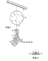
- the optical waveguide 1 carries four different light signals with the wavelengths ⁇ 1 , ⁇ 2 , ⁇ 3 and ⁇ 4 . Its end face lies in front of the spherical lens 8.
- the light emerging along the optical axis 6 is projected onto the diffraction grating 7 through the spherical lens 8. It is inclined by approximately 20 ° against the optical axis 6 and contains a line pattern of, for example, 800 lines per mm.
- the diffraction grating is covered with a thin reflective layer, which can be produced, for example, by vapor deposition of aluminum or silver.
- the incident light When reflecting on the diffraction grating, the incident light experiences a certain deflection, which is dependent on the wavelength of the incident light.
- the different light signals with different wavelengths are thus spatially separated and projected through the ball lens 8 onto the end faces of the optical fibers 2, 3, 4 and 5, so that they can be conducted in these optical fibers to separate light detectors or for further processing.
- the arrangement of the end faces of the optical fibers 1 to 5 is shown separately in FIG. 2. It can be seen that the end faces of the optical fibers 2, 3, 4 and 5 receiving the separated signals are arranged in a row in such a way that they adjoin one another almost immediately. Immediately next to this row, the end face of the optical waveguide 1 supplying the mixed signals is arranged.
- the fixation of the individual components to one another need not be discussed in more detail here; it is done primarily by embedding them in suitable plastic.
Landscapes
- Physics & Mathematics (AREA)
- General Physics & Mathematics (AREA)
- Optics & Photonics (AREA)
- Optical Couplings Of Light Guides (AREA)
- Optical Communication System (AREA)
- Optical Integrated Circuits (AREA)
Abstract
Description
- Die Erfindung betrifft eine Vorrichtung zum Auskoppeln von optischen Signalen verschiedener Wellenlängen aus einem Lichtwellenleiter in mehrere getrennte Lichtwellenleiter mit einem Beugungsgitter und mit einer Kugellinse im Strahlengang.
- Derartige Vorrichtungen können als Demultiplexer für die Signalübertragung in Anlagen verwendet werden, in denen verschiedene Signale mit verschiedenen Lichtwellenlängen über einen gemeinsamen Lichtwellenleiter übertragen werden.
- Bekannt ist bereits eine Vorrichtung zum Einkoppeln eines ersten optischen Signals mit einer ersten Wellenlänge in eine Übertragungsglasfaser und zum Auskoppeln eines in der Übertragungsglasfaser in entgegengesetzter Richtung zum ersten optischen Signal verlaufenden zweiten optischen Signals mit mindestens einer zur ersten Wellenlänge verschiedenen zweiten Wellenlänge, wobei die einzukoppelnden und ausgekoppelten optischen Signale in räumlich von einander getrennten weiteren Glasfasern verlaufen, bestehend aus einer zwischen der Übertragungsglasfaser und den weiteren Glasfasern angeordneten Abbildungsanordnung, in deren Pupille ein binäres, optisches Gitter liegt, und wobei weitere Glasfasern die in die Beugungsordnungen des Gitters abgebeugten zweiten optischen Signale aufnehmen, bei der das Gitter als Phasengitter ausgebildet und auf einer optischen Achse gemeinsam mit der Abbildungsordnung angeordnet ist, bei der das Phasengitter wenigstens annähernd ein Tastverhältnis von 1:1 und einen optischen Weglängenunterschied von wenigstens annähernd H = (N - 1) x h = nl x λI mit n1=1, 2, 3, .. besitzt, wobei N der Brechungsindex des Phasengittermaterials, h die Gitterhöhe und λI die Wellenlänge des in die Übertragungsglasfaser einzukoppelnden optischen Signals ist, und bei der das Phasengitter zusätzlich die Bedingung (N - 1) x h = (m1 + 1/2)A k mit m1 = 0, 1, 2, .. und k = II, III, .. wenigstens annähernd erfüllt (DE-OS 29 16 234). In einer Ausgestaltung dieses Standes der Technik befindet sich das Phasengitter zwischen zwei auf der optischen Achse angeordneten Linse.
- Eine Vorrichtung nach diesem Stand der Technik kann in bestimmten, in der zitierten Schrift beschriebenen Fällen als Demultiplexer vorteilhaft verwendet werden. Nachteilig ist aber die relativ hohe Dämpfung, die Lichtstrahlen beim Durchgang durch zwei Linsen und das Phasengitter erleiden. Ein weiterer Nachteil besteht in der relativ aufwendigen Herstellung eines solchen Phasengitters.
- Bekannt ist auch ein Verfahren zur Verbindung wenigstens zweier optischer Bauelemente auf einer gemeinsamen optischen Achse, wobei wenigstens eines der optischen Bauelemente eine aus Kern-und Mantelbereich bestehende Lichtleitfaser ist, und wenigstens ein anderes optisches Bauelement ein Koppelelement vorzugsweise eine Linse ist, bei dem das Lichtleitfaserende mit einer Ätzlösung behandelt wird, derart daß sich im Bereich des Faserkerns eine Vertiefung ausbildet, und bei dem das Koppelelement wenigstens zum Teil in die Vertiefung eingeführt wird (DE-OS 28 31 935). In einer Ausgestaltung dieses Standes der Technik wird als ein Koppelelement eine Kugellinse verwendet.
- In dieser zitierten Schrift werden Anwendungen der Kugellinse zum Koppeln zweier optischer Bauelemente beschrieben. Ein Hinweis auf die Kopplung mehrerer optischer Bauelemente miteinander ist dieser Schrift nicht zu entnehmen.
- Der Erfindung liegt die Aufgabe zugrunde, einen Demultiplexer der eingangs beschriebenen Art unter Verwendung bekannter und preisgünstig herstellbarer Bauteile zu schaffen, der möglichst geringe Dämpfungswerte für die Lichtsignale aufweist und eine vielfache Ausnutzung von Lichtwellenleitern gestattet.
- Diese Aufgabe wird erfindungsgemäß dadurch gelöst, daß das Beugungsgitter reflektierend ausgeführt ist, daß das Beugungsgitter gegen die optische Achse des Strahlenganges geneigt ist, und daß zwischen den Enden der Lichtwellenleiter und dem Beugungsgitter eine Kugellinse angeordnet ist.
- Eine Ausgestaltung der Erfindung ist im Unteranspruch angegeben.
- Die mit der Erfindung erzielbaren Vorteile bestehen insbeson- 'dere darin, daß ein preisgünstig und einfach herstellbarer Demultiplexer geschaffen wurde, dessen Lichtdämpfung kleiner ist als 3 dB, der wenigstens 4 Lichtsignale mit nahe beiainanderliegenden Wellenlänger voneinander trennen kann, wobei eine Übersprechdämpfung zwischen den Einzelsignalen von mehr als ,25 dB erreicht wird.
- Ein Ausführungsbeispiel der Erfindung ist in der Zeichnung dargestellt und wird im folgenden näher beschrieben. Es zeigen
- Fig. 1 einen Demultiplexer mit 4 Ausgängen in schematischer Darstellung
- Fig. 2 die Anordnung der Endflächen der Lichtwellenleiter vor der Kugellinse.
- Als bekannt werden vorausgesetzt die Funktion eines Lichtwellenleiters und sein Aufbau aus Mantel und Kern. Der Aufbau ist daher in Fig. 2 lediglich angedeutet, aber nicht mit zusätzlichen Bezugszeichen erklärt.
- In Fig. 1 ist der Aufbau eines Demultiplexers und die Anordnung seiner Teile schematisch dargestellt. Der Lichtwellenleiter 1 führt im Beispiel vier verschiedene Lichtsignale mit den Wellenlängen λ1,λ2,λ3 undλ4. Seine Endfläche liegt vor der Kugellinse 8. Das entlang der optischen Achse 6 austretende Licht wird durch die Kugellinse 8 auf das Beugungsgitter 7 projeziert. Es ist um etwa 20° gegen die optische Achse 6 geneigt und enthält ein Linienmuster von beispielsweise 800 Linien pro mm. Das Beugungsgitter ist mit einer dünnen reflektierenden Schicht bedeckt, die beispielsweise durch Aufdampfen von Aluminium oder Silber hergestellt sein kann. Bei der Reflektion am Beugungsgitter erfährt das auftreffende Licht eine bestimmte Ablenkung, die abhängig ist von der Wellenlänge des auftreffenden Lichtes. Die verschiedenen Lichtsignale mit verschiedenen Wellenlängen werden hier also räumlich getrennt und durch die Kugellinse 8 auf die Endflächen der Lichtwellenleiter 2, 3, 4 und 5 projeziert, so daß sie in diesen Lichtwellenleitern zu getrennten Lichtdetektoren bzw. zur sonstigen Weiterverarbeitung geleitet werden können. Die Anordnung der Endflächen der Lichtwellenleiter 1 bis 5 ist in Fig. 2 gesondert dargestellt. Es ist erkennbar, daß die Endflächen der die getrennten Signale aufnehmenden Lichtwellenleiter 2, 3, 4 und 5 in einer Reihe derart angeordnet sind, daß sie fast unmittelbar aneinandergrenzen. Unmittelbar neben dieser Reihe ist die Endfläche des die gemischten Signale zuführenden Lichtwellenleiters 1 angeordnet. Auf die Fixierung der einzelnen Bauteile zueinander braucht hier nicht näher eingegangen zu werden, sie erfolgt vorwiegend durch Einbettung in geeigneten Kunststoff.
Claims (2)
Priority Applications (1)
| Application Number | Priority Date | Filing Date | Title |
|---|---|---|---|
| AT82104692T ATE34622T1 (de) | 1981-08-27 | 1982-05-28 | Vorrichtung zum getrennten auskoppeln von optischen signalen verschiedener wellenlaengen. |
Applications Claiming Priority (2)
| Application Number | Priority Date | Filing Date | Title |
|---|---|---|---|
| DE8125009U | 1981-08-27 | ||
| DE19818125009U DE8125009U1 (de) | 1981-08-27 | 1981-08-27 | Vorrichtung zum getrennten auskoppeln von optischen signalen verschiedener wellenlaengen |
Publications (3)
| Publication Number | Publication Date |
|---|---|
| EP0073300A2 true EP0073300A2 (de) | 1983-03-09 |
| EP0073300A3 EP0073300A3 (en) | 1985-10-23 |
| EP0073300B1 EP0073300B1 (de) | 1988-05-25 |
Family
ID=6730692
Family Applications (1)
| Application Number | Title | Priority Date | Filing Date |
|---|---|---|---|
| EP82104692A Expired EP0073300B1 (de) | 1981-08-27 | 1982-05-28 | Vorrichtung zum getrennten Auskoppeln von optischen Signalen verschiedener Wellenlängen |
Country Status (4)
| Country | Link |
|---|---|
| EP (1) | EP0073300B1 (de) |
| AT (1) | ATE34622T1 (de) |
| DE (2) | DE8125009U1 (de) |
| DK (1) | DK320182A (de) |
Cited By (4)
| Publication number | Priority date | Publication date | Assignee | Title |
|---|---|---|---|---|
| EP0123332A3 (de) * | 1983-03-23 | 1987-02-04 | Philips Patentverwaltung GmbH | Optischer Multiplexer und Demultiplexer |
| US4708426A (en) * | 1984-07-09 | 1987-11-24 | U.S. Philips Corp. | Electro-optical device comprising a laser diode, and input transmission fibre and an output transmission fibre |
| EP0242574A3 (en) * | 1986-04-04 | 1989-10-04 | Kernforschungszentrum Karlsruhe Gmbh | Procedure for the manufacture of an optical component having one or more echelette-gratings and device thereby obtained |
| GB2251957A (en) * | 1990-11-29 | 1992-07-22 | Toshiba Kk | "Wavelength (DE) multiplex optical coupler" |
Family Cites Families (2)
| Publication number | Priority date | Publication date | Assignee | Title |
|---|---|---|---|---|
| US4153330A (en) * | 1977-12-01 | 1979-05-08 | Bell Telephone Laboratories, Incorporated | Single-mode wavelength division optical multiplexer |
| DE2831935C2 (de) * | 1978-07-20 | 1987-05-07 | Licentia Patent-Verwaltungs-Gmbh, 6000 Frankfurt | Verfahren zur Verbindung wenigsten zweier optischer Bauelemente auf einer gemeinsamen optischen Achse |
-
1981
- 1981-08-27 DE DE19818125009U patent/DE8125009U1/de not_active Expired
-
1982
- 1982-05-28 EP EP82104692A patent/EP0073300B1/de not_active Expired
- 1982-05-28 AT AT82104692T patent/ATE34622T1/de not_active IP Right Cessation
- 1982-05-28 DE DE8282104692T patent/DE3278543D1/de not_active Expired
- 1982-07-16 DK DK320182A patent/DK320182A/da not_active Application Discontinuation
Cited By (5)
| Publication number | Priority date | Publication date | Assignee | Title |
|---|---|---|---|---|
| EP0123332A3 (de) * | 1983-03-23 | 1987-02-04 | Philips Patentverwaltung GmbH | Optischer Multiplexer und Demultiplexer |
| US4708426A (en) * | 1984-07-09 | 1987-11-24 | U.S. Philips Corp. | Electro-optical device comprising a laser diode, and input transmission fibre and an output transmission fibre |
| EP0242574A3 (en) * | 1986-04-04 | 1989-10-04 | Kernforschungszentrum Karlsruhe Gmbh | Procedure for the manufacture of an optical component having one or more echelette-gratings and device thereby obtained |
| GB2251957A (en) * | 1990-11-29 | 1992-07-22 | Toshiba Kk | "Wavelength (DE) multiplex optical coupler" |
| GB2251957B (en) * | 1990-11-29 | 1993-12-15 | Toshiba Kk | Optical coupler |
Also Published As
| Publication number | Publication date |
|---|---|
| EP0073300A3 (en) | 1985-10-23 |
| ATE34622T1 (de) | 1988-06-15 |
| DK320182A (da) | 1983-02-28 |
| DE3278543D1 (en) | 1988-06-30 |
| DE8125009U1 (de) | 1981-12-24 |
| EP0073300B1 (de) | 1988-05-25 |
Similar Documents
| Publication | Publication Date | Title |
|---|---|---|
| DE3530928C2 (de) | ||
| DE3012184C2 (de) | ||
| DE69628373T2 (de) | Optischer Koppler mit faseroptischen Steckerstiften | |
| DE69618087T2 (de) | Mechanischer faseroptischer Schalter | |
| DE2916184C2 (de) | ||
| EP0194612A2 (de) | Wellenlängenmultiplexer oder -demultiplexer | |
| DE3413703A1 (de) | Optischer multiplexer/demultiplexer | |
| DE2159327B2 (de) | Vorrichtung zur Justierung zweier optischer Bauelemente | |
| DE3414724C2 (de) | ||
| DE3503203A1 (de) | Optischer multiplexer/demultiplexer | |
| DE3208753A1 (de) | Epidunkles beleuchtungssystem | |
| DE2905916A1 (de) | Faseroptische uebertragungsvorrichtung | |
| DE19711121A1 (de) | Verzweigende Lichtwellenleiteranordnung | |
| DE2720108A1 (de) | Optischer entzerrer zur signaluebertragung ueber optische mehrmoden- wellenleiter mit einem sprunghaften brechungsindexprofil | |
| DE3780802T2 (de) | Einrichtung mit einer planaren optischen schaltung und daran gekoppelte optische faser. | |
| DE2905360A1 (de) | Optische kopplungsvorrichtung | |
| EP0073300B1 (de) | Vorrichtung zum getrennten Auskoppeln von optischen Signalen verschiedener Wellenlängen | |
| DE3422972C2 (de) | Vorrichtung zum Positionieren und Fixieren von Lichtleitfasern in einer parallelen Anordnung zu einem Lichtleitfaserarray | |
| DE3024104A1 (de) | Integrierte mikrooptische vorrichtung zur verwendung mit multimode-lichtleitfasern und verfahren zu ihrer herstellung | |
| DE3214042A1 (de) | Faseroptische koppelanordnung | |
| DE68918423T2 (de) | Optische Vorrichtung für das Beobachten eines ausgedehnten Objektes. | |
| DE3900406C2 (de) | Verfahren zur Überprüfung der gegenseitigen Ausrichtung von nebeneinander angeordneten Enden von Glasfasern von Bandfaserkabeln | |
| DE19500214A1 (de) | Verfahren und Vorrichtung zum Umschalten von optischen Signalleitungen | |
| DE3908530C1 (de) | ||
| DE1958036A1 (de) | Anordnung zur Scharfeinstellung |
Legal Events
| Date | Code | Title | Description |
|---|---|---|---|
| PUAI | Public reference made under article 153(3) epc to a published international application that has entered the european phase |
Free format text: ORIGINAL CODE: 0009012 |
|
| AK | Designated contracting states |
Designated state(s): AT CH DE LI NL |
|
| 17P | Request for examination filed |
Effective date: 19830419 |
|
| PUAL | Search report despatched |
Free format text: ORIGINAL CODE: 0009013 |
|
| AK | Designated contracting states |
Designated state(s): AT CH DE LI NL |
|
| 17Q | First examination report despatched |
Effective date: 19870121 |
|
| GRAA | (expected) grant |
Free format text: ORIGINAL CODE: 0009210 |
|
| AK | Designated contracting states |
Kind code of ref document: B1 Designated state(s): AT CH DE LI NL |
|
| REF | Corresponds to: |
Ref document number: 34622 Country of ref document: AT Date of ref document: 19880615 Kind code of ref document: T |
|
| REF | Corresponds to: |
Ref document number: 3278543 Country of ref document: DE Date of ref document: 19880630 |
|
| PLBE | No opposition filed within time limit |
Free format text: ORIGINAL CODE: 0009261 |
|
| STAA | Information on the status of an ep patent application or granted ep patent |
Free format text: STATUS: NO OPPOSITION FILED WITHIN TIME LIMIT |
|
| 26N | No opposition filed | ||
| PGFP | Annual fee paid to national office [announced via postgrant information from national office to epo] |
Ref country code: DE Payment date: 19890723 Year of fee payment: 8 |
|
| PGFP | Annual fee paid to national office [announced via postgrant information from national office to epo] |
Ref country code: AT Payment date: 19900521 Year of fee payment: 9 |
|
| PGFP | Annual fee paid to national office [announced via postgrant information from national office to epo] |
Ref country code: NL Payment date: 19900531 Year of fee payment: 9 |
|
| PGFP | Annual fee paid to national office [announced via postgrant information from national office to epo] |
Ref country code: CH Payment date: 19900824 Year of fee payment: 9 |
|
| PG25 | Lapsed in a contracting state [announced via postgrant information from national office to epo] |
Ref country code: DE Effective date: 19910201 |
|
| PG25 | Lapsed in a contracting state [announced via postgrant information from national office to epo] |
Ref country code: AT Effective date: 19910528 |
|
| PG25 | Lapsed in a contracting state [announced via postgrant information from national office to epo] |
Ref country code: LI Effective date: 19910531 Ref country code: CH Effective date: 19910531 |
|
| PG25 | Lapsed in a contracting state [announced via postgrant information from national office to epo] |
Ref country code: NL Effective date: 19911201 |
|
| NLV4 | Nl: lapsed or anulled due to non-payment of the annual fee | ||
| REG | Reference to a national code |
Ref country code: CH Ref legal event code: PL |