EP0073091B1 - Automatic locking safety belt retraction apparatus with resetting means - Google Patents
Automatic locking safety belt retraction apparatus with resetting means Download PDFInfo
- Publication number
- EP0073091B1 EP0073091B1 EP82301360A EP82301360A EP0073091B1 EP 0073091 B1 EP0073091 B1 EP 0073091B1 EP 82301360 A EP82301360 A EP 82301360A EP 82301360 A EP82301360 A EP 82301360A EP 0073091 B1 EP0073091 B1 EP 0073091B1
- Authority
- EP
- European Patent Office
- Prior art keywords
- link
- clamping
- webbing
- reset
- vehicle
- Prior art date
- Legal status (The legal status is an assumption and is not a legal conclusion. Google has not performed a legal analysis and makes no representation as to the accuracy of the status listed.)
- Expired
Links
Images


Classifications
-
- B—PERFORMING OPERATIONS; TRANSPORTING
- B60—VEHICLES IN GENERAL
- B60R—VEHICLES, VEHICLE FITTINGS, OR VEHICLE PARTS, NOT OTHERWISE PROVIDED FOR
- B60R22/00—Safety belts or body harnesses in vehicles
- B60R22/18—Anchoring devices
- B60R22/185—Anchoring devices with stopping means for acting directly upon the belt in an emergency, e.g. by clamping or friction
Definitions
- the present invention relates to safety belt webbing emergency locking apparatus for use in automotive vehicles.
- Safety belt webbing emergency locking apparatus have been developed for use in automotive vehicles including retractors upon which safety belt webbing is stored with vehicle inertia sensor means for automatically locking the retractor against further belt protraction therefrom in the event of deceleration or acceleration of the vehicle as may occur in emergency conditions.
- the present invention is intended for use with a safety belt webbing emergency locking apparatus of the type disclosed in our European Patent Specification 0056894 which constitutes prior art of the type referred to in Art. 54(3) EPC, having clamping means including one or more wedged shaped clamp members for clamping directly upon the webbing, biasing means for biasing the clamping means to a webbing clamping position preventing safety belt movement, and a vehicle inertia activating means for sensing changes in vehicle inertia of more than a predetermined amount.
- the primary aim of the present invention is to provide such an apparatus wherein the clamping means is automatically reset after activation by movement of a part of the vehicle separate from the apparatus.
- a safety belt webbing emergency locking apparatus having a vehicle inertia sensor actuated safety belt clamping means for preventing safety belt webbing protraction relative to the apparatus, said clamping means being permanently biased to a webbing clamping position and normally held in a belt release position by releasable retaining means, vehicle inertia sensor means for operating said releasable retaining means to release said clamping means to allow said clamping means to clamp said webbing preventing further movement thereof, and automatically operating reset means for resetting said retaining means to move said clamping means to said webbing release position and hold it in said position in response to operation of a part of the vehicle in a predetermined manner, said part of the vehicle not being part of the locking apparatus.
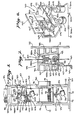
- FIG. 10 an exemplary embodiment of safety belt webbing emergency locking apparatus is illustrated generally at 10 wherein a safety belt webbing 11 is wound upon a conventional safety belt retractor 12 having a webbing storage spool 13 with spool ratchet wheels 14 and 15 being engageable by lock bar 16 in known manner.
- Lock bar 16 is pivoted at its outer ends in the retractor frame side walls 17 and 18, respectively, the frame being of conventional U-shaped configuration with the frame base 19 being mounted to the vehicle frame or support structure 20 by a base plate or vehicle floor 21.
- Vertical column 22 is exemplary of the B-pillar of a conventional automobile, the installation of the safety belt retractor being in accordance with known methods, the illustration in Figures 1, and 3 being merely illustrative thereof.
- the exemplary safety belt retractor is provided in known manner with a vehicle inertia sensor means, indicated generally at 25, which, in the exemplary embodiment, includes a conventional pendulum having a mass 26 supported on stem 27 depending from head 28, head 28 being mounted in an aperture in support bar 29 beneath lock bar 16 in position to engage it and move it into engagement with the ratchet wheels 14 and 15 when the vehicle encounters a change of inertia of more than a predetermined amount.
- Webbing 11 is normally biased toward a wound up position on the retractor spool by a conventional wind up spring provided within spring housing 30 in conventional manner.
- the exemplary emergency locking apparatus indicated generally at 10 is of the type having clamping means, indicated generally at 35, for clamping directly upon webbing 11 when an associated sensor means senses a vehicle inertia change of more than a predetermined amount.
- Clamping means 35 may be provided to clamp webbing 11 at higher levels of vehicle inertia change, referred to as higher G levels, than the retractor indicated generally at 12 is set.
- the clamping means may therefore be employed to positively clamp webbing 11 against protraction relative to the emergency locking apparatus 10 in vehicle collision circumstances while the retractor 12 may be operable in response to sudden stopping of the vehicle or the like.
- the exemplary clamping means indicated generally at 35 is not self resetting without the provision of the automatically operating reset means of the present invention which will be described subsequently in association therewith.
- the exemplary clamping means includes a housing 36 having a front wall 37, back wall 38, right hand side wall 39a and a left hand side wall 39b with the housing being mounted on the column 22 which is exemplary of a B-pillar of a modern day automotive vehicle.
- Housing 36 is provided with a webbing passage, indicated generally at 40 in Figure 7, through which the webbing 11 normally passes freely.
- a base clamp block 41 is provided with a webbing facing inclined surface 42 opposite to an opposing clamp block 43 presenting an inclined surface 44 also facing inwardly toward webbing 11, surfaces 42 and 44 opposing each other and being convergent in an upward direction relative to housing 36.
- a pair of wedged shaped clamp members 45a and 45b are provided in assembled relation between blocks 41 and 43 and riding against the block surfaces 42 and 44 as best seen in Figure 7.
- Clamp member 45a is provided with a depending foot portion 46 which has a horizontally extending projection 47 which cooperates with the wedge actuating means as subsequently described.
- Wedge members 45a and 45b are formed with mating tongue and groove type side engagements, laterally outwardly of webbing 11 as side ears 48a and 48b on wedge member 45b fit within slide grooves, as groove 49 in Figure 7, with spring biasing means normally urging the wedge members apart when in a release position to facilitate free sliding movement of webbing 11 thereby.
- the clamp members 45a and 45b are preferably coated with a layer of pliant, high strength resilient material having a preferably relatively low coefficient of friction characteristic on the surfaces thereof which face toward webbing 11 to facilitate even distribution of clamping loads upon the webbing when the wedge members are moved to a webbing clamping position.
- Actuating means for moving the wedge members 45a and 45b upwardly in Figure 7 to a webbing clamping position are provided in the exemplary embodiment and are indicated generally at 50 in the drawings.
- Such means includes a support bracket 51 having a top flange 52 mounted by fasteners, such as screws 53, to the front wall 37 of housing 36.
- Support bracket 50 is further provided with a bottom flange 54 including aperture 55 and a side flange 56 as discussed hereinafter.
- the support bracket mounts biasing means, indicated generally at 60, for normally biasing wedge members 45a and 45b toward a webbing clamping position, releaseable retaining means indicated generally at 70 for normally holding the wedge members from movement under the urging of the biasing means and a vehicle inertia sensor means, indicated generally at 90, for operating the releaseable retaining means 70 to allow movement of wedge member 45a and 45b into webbing clamping position under the urging of the spring means indicated generally at 60 when the inertia sensor means senses a change in vehicle inertia of more than a predetermined amount.
- the exemplary biasing means, indicated generally at 60 includes a coil spring 61 having one free end 62 abutting beneath a portion of bracket 51 where the bracket is offset inwardly relative apparatus 10 and the bracket flange 52 from which the bracket body depends. An opposite end 63 of spring 61 bears against a portion of the releaseable retaining means 70 which will now be described.
- Release retaining means indicated generally at 70 in the exemplary embodiment include a trigger link 71 which is adapted to be actuated by the head 93 of the inertia sensor 90.
- Link 71 is provided with a contact pad 72 overlying pendulum head 93 and is pivoted at its opposite end by means of the downturned end 73 lying outwardly of slot 55 in flange 56, link 71 riding in slot 55 in pivotal fashion and being retained there by downturned end 73.
- An overcentre link 75 as best seen in Figures 4, 5 and 6 is of generally U-shaped configuration having the ends of its two side arms slotted, as slot 76 in Figure 4, to pivotally received portions of trigger link 71, the inner side 77 of Figure 6 receiving trigger link ear 77a and the outer side 78 receiving a bar portion 78a of the trigger link as best seen in Figure 6.
- Bar 78a is formed by the provision of an aperture 79 in link 71 as seen in Figure 6 in plan view.
- reaction link 80 is pivotally mounted on pivot pin 81 mounted to bracket 51 with an apertured arm 82 receiving projection 47 therethrough as best seen in Figures 4, 5 and 6.
- reaction link 80 has an oppositely extending arm 83 having a bottom flange 84 against which biasing means spring arm 63 abuts.
- Flange 84 is further provided with an outwardly extending arm 85 pivotally engaging overcentre link 75 with an end tab 86 lying outwardly of aperture 87 provided in side wall 78 of link 75.
- the releaseable retaining means indicated generally at 70 includes the trigger link 71 overcenter link 75 and actuator link 80 for normally holding the wedge members 45a and 45b in a webbing release position.
- the releaseable retaining means is in the position of Figure 4 wherein the bias of spring means 60, as applied by spring end 63 against flange 84 of actuator link 80 tends to move link arm 82 upwardly in Figure 4 to raise projection 47 and the associated wedge members 45a and 45b upwardly in Figure 7.
- automatically operating reset means are provided for resetting the retaining means from the release position of Figure 5, wherein the clamping means clamps webbing 11, to the releasable retaining position of Figure 4 wherein the associated clamping means is in a webbing release position.
- such means are illustrated generally at 100 in Figure 2 and include a door operated mechanical switch 101 having a cable 102 within cable sheath 103 connected by a cable end fitting 104 as seen in Figures 1, 2, 3 and 6 to the free end of trigger link 71.
- the exemplary door operated switch 101 is provided with a slide rod or button 105 which is normally biased by a spring within housing 106 for urging button 105 outwardly of the vehicle frame 107 to which switch 101 is mounted via mounting cap 108.
- Slide rod or button 105 is connected at its inner end to cable 102 in such a manner that when the vehicle door is opened, the spring within the housing 106 forces button 105 outwardly of the housing 106 drawing cable 102 through cable sheath 103, which is fixed by cable support 109 mounted to support bracket 51 to thus pull the cable end fitting 104 and the associated free end of trigger link 71 downwardly in Figures 1-5 to move the trigger link 71, its associated overcentre link 75 and actuator link 80 from the release position of Figure 5 to the retaining position of Figure 4.
- the door open position for the exemplary reset means is illustrated in Figure 2 with trigger means 104 being pulled downwardly to the position of Figure 4.
- the cable end fitting 104 is adapted to ride upwardly through an apertured tab portion of the free end of trigger link 71 so that on closing of the vehicle door, button 105 will move inwardly of housing 106 from the position of Figure 2 to force the cable 102 upwardly relative the free end of the trigger link leaving it free to move upwardly to the position of Figure 5 on actuation of the trigger by the exemplary vehicle inertia sensor means indicated generally at 90.
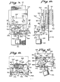
- FIG. 8 An alternative exemplary embodiment of the releasable retaining means for normally holding the clamping means in a webbing release position and automatically operating reset means for resetting and retaining means is shown in Figures 8 through 13.
- This exemplary releasable means operates in the same manner as the prior embodiment with like parts thereof being given like numerals plus one hundred.
- the alternative embodiment of releasable retaining means includes a support bracket indicated generally at 150 having a bracket body 151 supported by a flange 152 of the clamping means housing 136.
- a single wedge member 145 is positioned between a rear clamp lock 141 and a front clamp lock 143 to wedgely clamp webbing 111 when foot 146 is raised by the actuator arm 182.
- trigger link 171 having pad 172 on its free end is pivoted at its rearend on support flange 156 with a depending tab 173 maintaining it on the support.
- actuator link 180 is biased by spring arm 163 in a counterclockwise direction about its pivot pin 183 to urge the left hand end of overcenter link 175 through its connection with link arm 181 in a downward direction.
- the right hand arm 182 of actuator link 180 protrudes through an appropriate aperture in support 151 to underlie foot 146 of wedge member 145.
- the automatically operating reset means may include a solenoid 200 having a moving rod 201 passing through an appropriate aperture in the outer end of trigger link ear 178a as best seen in Figures 8-13.
- the upper end 203 is larger than the aperture in ear 178a so that movement of rod 201 into the solenoid body will pull trigger link 171 back down into a reset condition.
- Operation of solenoid 200 may be accomplished in response to operation of the vehicle door by having an appropriate electrical circuit including lead line 204 running to a door operated switch, indicated generally at 205 and known per se, which is connected into a conventional vehicle battery indicated generally at 206.
- normally open switch 205 closes under an appropriate spring bias to actuate the electrical circuitry associated with solenoid 200 to pull trigger link 171 from the position of Figure 12 to the position of Figure 9, thus resetting the releasable retaining means described and allowing the wedge member 145 to be lowered through the engagement of its foot 146 with retainer means link arm 182 to the position of Figure 10.
Description
- The present invention relates to safety belt webbing emergency locking apparatus for use in automotive vehicles.
- Safety belt webbing emergency locking apparatus have been developed for use in automotive vehicles including retractors upon which safety belt webbing is stored with vehicle inertia sensor means for automatically locking the retractor against further belt protraction therefrom in the event of deceleration or acceleration of the vehicle as may occur in emergency conditions.
- It is the primary object of the present invention to provide a means for automatically resetting the safety belt webbing clamping means and its associated actuating means to a webbing release position after a vehicle emergency condition has ended in order to obviate the need for a manual resetting thereof.
- Generally stated, the present invention is intended for use with a safety belt webbing emergency locking apparatus of the type disclosed in our European Patent Specification 0056894 which constitutes prior art of the type referred to in Art. 54(3) EPC, having clamping means including one or more wedged shaped clamp members for clamping directly upon the webbing, biasing means for biasing the clamping means to a webbing clamping position preventing safety belt movement, and a vehicle inertia activating means for sensing changes in vehicle inertia of more than a predetermined amount. The primary aim of the present invention is to provide such an apparatus wherein the clamping means is automatically reset after activation by movement of a part of the vehicle separate from the apparatus.
- According to the present invention there is provided a safety belt webbing emergency locking apparatus having a vehicle inertia sensor actuated safety belt clamping means for preventing safety belt webbing protraction relative to the apparatus, said clamping means being permanently biased to a webbing clamping position and normally held in a belt release position by releasable retaining means, vehicle inertia sensor means for operating said releasable retaining means to release said clamping means to allow said clamping means to clamp said webbing preventing further movement thereof, and automatically operating reset means for resetting said retaining means to move said clamping means to said webbing release position and hold it in said position in response to operation of a part of the vehicle in a predetermined manner, said part of the vehicle not being part of the locking apparatus.
- Reference is now made to the accompanying drawings, in which:
- Figure 1 is an elevational view of an exemplary safety belt webbing emergency locking apparatus of the type having clamping means for clamping a safety belt webbing stored upon a safety belt retractor.
- Figure 2 is a side view of the apparatus of Figure 1.
- Figure 3 is an elevation view as in Figure 1 showing the clamping means and associated safety belt retractor in belt clamping and locking positions respectively.
- Figure 4 is a detail view of a releaseable retaining means in accordance with the present invention shown in a position wherein the associated clamping means is held in a belt release position.
- Figure 5 is a view as in Figure 4 showing the releaseable retaining means in a release wherein the associated clamping means is in a belt clamping position.
- Figure 6 is a horizontal section view of the apparatus of Figure 4taken therein along the plane VI-VI.
- Figure 7 is a vertical section view of the apparatus of Figure 4taken therein along the plane VII-VII.
- Figure 8 is a detail view of another embodiment of releaseable retaining means and automatically operating reset means in accordance with the present invention.
- Figure 9 is a front view of the apparatus of Figure 8 shown in association with an alternative exemplary embodiment of clamping means.
- Figure 10 is a side view partially in section of the apparatus of Figure 9.
- Figure 11 is a horizontal section view of the apparatus of Figure 9 taken therein along the plane XI-XI.
- Figure 12 is a detail view of the apparatus of Figure 9 showing the releaseable retaining means in a released position.
- Figure 13 is an exploded view of the releaseable retaining means and automatically operating reset means of Figures 8 through 12.
- Referring now to Figures 1, 2 and 3, initially, an exemplary embodiment of safety belt webbing emergency locking apparatus is illustrated generally at 10 wherein a
safety belt webbing 11 is wound upon a conventionalsafety belt retractor 12 having awebbing storage spool 13 withspool ratchet wheels lock bar 16 in known manner.Lock bar 16 is pivoted at its outer ends in the retractorframe side walls frame base 19 being mounted to the vehicle frame orsupport structure 20 by a base plate orvehicle floor 21.Vertical column 22 is exemplary of the B-pillar of a conventional automobile, the installation of the safety belt retractor being in accordance with known methods, the illustration in Figures 1, and 3 being merely illustrative thereof. - The exemplary safety belt retractor, indicated generally at 12, is provided in known manner with a vehicle inertia sensor means, indicated generally at 25, which, in the exemplary embodiment, includes a conventional pendulum having a
mass 26 supported onstem 27 depending fromhead 28,head 28 being mounted in an aperture insupport bar 29 beneathlock bar 16 in position to engage it and move it into engagement with theratchet wheels Webbing 11 is normally biased toward a wound up position on the retractor spool by a conventional wind up spring provided withinspring housing 30 in conventional manner. - The exemplary emergency locking apparatus indicated generally at 10 is of the type having clamping means, indicated generally at 35, for clamping directly upon
webbing 11 when an associated sensor means senses a vehicle inertia change of more than a predetermined amount. Clamping means 35 may be provided to clampwebbing 11 at higher levels of vehicle inertia change, referred to as higher G levels, than the retractor indicated generally at 12 is set. - The clamping means may therefore be employed to positively clamp webbing 11 against protraction relative to the
emergency locking apparatus 10 in vehicle collision circumstances while theretractor 12 may be operable in response to sudden stopping of the vehicle or the like. As will be discussed more fully hereinafter, while the retractor indicated generally at 12 is self resetting when an emergency condition ceases, the exemplary clamping means indicated generally at 35 is not self resetting without the provision of the automatically operating reset means of the present invention which will be described subsequently in association therewith. - Referring now to Figure 7, in addition to Figures 1 through 3, the exemplary clamping means, indicated generally at 35, includes a
housing 36 having afront wall 37,back wall 38, right hand side wall 39a and a lefthand side wall 39b with the housing being mounted on thecolumn 22 which is exemplary of a B-pillar of a modern day automotive vehicle.Housing 36 is provided with a webbing passage, indicated generally at 40 in Figure 7, through which thewebbing 11 normally passes freely. Abase clamp block 41 is provided with a webbing facinginclined surface 42 opposite to anopposing clamp block 43 presenting aninclined surface 44 also facing inwardly towardwebbing 11,surfaces housing 36. A pair of wedged shapedclamp members blocks block surfaces Clamp member 45a is provided with a dependingfoot portion 46 which has a horizontally extendingprojection 47 which cooperates with the wedge actuating means as subsequently described. Wedgemembers webbing 11 asside ears wedge member 45b fit within slide grooves, asgroove 49 in Figure 7, with spring biasing means normally urging the wedge members apart when in a release position to facilitate free sliding movement ofwebbing 11 thereby. Theclamp members webbing 11 to facilitate even distribution of clamping loads upon the webbing when the wedge members are moved to a webbing clamping position. - Actuating means for moving the
wedge members support bracket 51 having atop flange 52 mounted by fasteners, such asscrews 53, to thefront wall 37 ofhousing 36.Support bracket 50 is further provided with abottom flange 54 includingaperture 55 and aside flange 56 as discussed hereinafter. The support bracket mounts biasing means, indicated generally at 60, for normally biasingwedge members wedge member - The exemplary biasing means, indicated generally at 60 includes a
coil spring 61 having onefree end 62 abutting beneath a portion ofbracket 51 where the bracket is offset inwardlyrelative apparatus 10 and thebracket flange 52 from which the bracket body depends. Anopposite end 63 ofspring 61 bears against a portion of the releaseable retaining means 70 which will now be described. - Release retaining means, indicated generally at 70 in the exemplary embodiment include a
trigger link 71 which is adapted to be actuated by thehead 93 of theinertia sensor 90.Link 71 is provided with acontact pad 72 overlyingpendulum head 93 and is pivoted at its opposite end by means of thedownturned end 73 lying outwardly ofslot 55 inflange 56,link 71 riding inslot 55 in pivotal fashion and being retained there bydownturned end 73. Anovercentre link 75, as best seen in Figures 4, 5 and 6 is of generally U-shaped configuration having the ends of its two side arms slotted, asslot 76 in Figure 4, to pivotally received portions oftrigger link 71, the inner side 77 of Figure 6 receiving trigger link ear 77a and theouter side 78 receiving abar portion 78a of the trigger link as best seen in Figure 6.Bar 78a is formed by the provision of an aperture 79 inlink 71 as seen in Figure 6 in plan view. - A
reaction link 80 is pivotally mounted onpivot pin 81 mounted tobracket 51 with an aperturedarm 82 receivingprojection 47 therethrough as best seen in Figures 4, 5 and 6. Referring particularly to Figure 6,reaction link 80 has an oppositely extendingarm 83 having a bottom flange 84 against which biasing meansspring arm 63 abuts. Flange 84 is further provided with an outwardly extendingarm 85 pivotally engagingovercentre link 75 with anend tab 86 lying outwardly of aperture 87 provided inside wall 78 oflink 75. - As can be seen from a comparison of Figures 4 and 5, together with the plan view of Figure 6, the releaseable retaining means indicated generally at 70, includes the
trigger link 71overcenter link 75 andactuator link 80 for normally holding thewedge members spring end 63 against flange 84 ofactuator link 80 tends to movelink arm 82 upwardly in Figure 4 to raiseprojection 47 and the associatedwedge members spring 61 of the biasing means with the retaining means in the position of Figure 4 is blocked by overcenter link 75 since the force ofspring arm 63 tends to push overcenter link 75 downwardly in a counterclockwise direction about its pivotal connection to triggerlink 71 via tab 77a andbar 78a lying in appropriate slots formed in the side walls oflink 75 as described previously. However, on swinging movement ofpendulum mass 91 from the position of Figure 4 to the position of Figure 5 an upward movement oftrigger link pad 72 movingtrigger link 71 in a clockwise direction around its pivotal endadjacent flange 56, raises the right hand end of overcenter link 75 in Figure 4 in a generally counterclockwise direction around its pivot point ofarm 85 until the right hand end oflink 75 is vertically overcome such thatlink 75 pivots under the action ofspring arm 63 in a counterclockwise direction to the position of Figure 5 whereinactuator link arm 82 has raised thewedge members projection 47. - As particularly contemplated within the present invention, automatically operating reset means are provided for resetting the retaining means from the release position of Figure 5, wherein the clamping means
clamps webbing 11, to the releasable retaining position of Figure 4 wherein the associated clamping means is in a webbing release position. In the exemplary embodiment, such means are illustrated generally at 100 in Figure 2 and include a door operatedmechanical switch 101 having acable 102 withincable sheath 103 connected by a cable end fitting 104 as seen in Figures 1, 2, 3 and 6 to the free end oftrigger link 71. The exemplary door operatedswitch 101 is provided with a slide rod orbutton 105 which is normally biased by a spring withinhousing 106 forurging button 105 outwardly of thevehicle frame 107 to whichswitch 101 is mounted viamounting cap 108. Slide rod orbutton 105 is connected at its inner end tocable 102 in such a manner that when the vehicle door is opened, the spring within thehousing 106forces button 105 outwardly of thehousing 106drawing cable 102 throughcable sheath 103, which is fixed by cable support 109 mounted to supportbracket 51 to thus pull the cable end fitting 104 and the associated free end oftrigger link 71 downwardly in Figures 1-5 to move thetrigger link 71, its associatedovercentre link 75 andactuator link 80 from the release position of Figure 5 to the retaining position of Figure 4. The door open position for the exemplary reset means is illustrated in Figure 2 with trigger means 104 being pulled downwardly to the position of Figure 4. Thecable end fitting 104 is adapted to ride upwardly through an apertured tab portion of the free end oftrigger link 71 so that on closing of the vehicle door,button 105 will move inwardly ofhousing 106 from the position of Figure 2 to force thecable 102 upwardly relative the free end of the trigger link leaving it free to move upwardly to the position of Figure 5 on actuation of the trigger by the exemplary vehicle inertia sensor means indicated generally at 90. - An alternative exemplary embodiment of the releasable retaining means for normally holding the clamping means in a webbing release position and automatically operating reset means for resetting and retaining means is shown in Figures 8 through 13. This exemplary releasable means operates in the same manner as the prior embodiment with like parts thereof being given like numerals plus one hundred.
- Referring to Figures 8 through 13, the alternative embodiment of releasable retaining means includes a support bracket indicated generally at 150 having a
bracket body 151 supported by aflange 152 of the clamping means housing 136. As seen particularly in Figure 10 in this alternative exemplary embodiment, asingle wedge member 145 is positioned between arear clamp lock 141 and afront clamp lock 143 to wedgely clamp webbing 111 when foot 146 is raised by theactuator arm 182. As before,trigger link 171 havingpad 172 on its free end is pivoted at its rearend onsupport flange 156 with a dependingtab 173 maintaining it on the support. When the inertia sensor indicated generally at 190 senses a change in vehicle inertia,mass 191swings pendulum head 193 beneathpad 172 to cause raising of the free end oftrigger 171. Thetrigger ears arms overcenter link 175 about itspivot pin 186 and, when sufficient tilting movement has been accomplished to free the action ofspring 161, to tilt from the position of Figure 9 to that of Figure 12 under urging of the biasing means indicated generally at 160. As best seen in the exploded view of Figure 13actuator link 180 is biased byspring arm 163 in a counterclockwise direction about itspivot pin 183 to urge the left hand end ofovercenter link 175 through its connection withlink arm 181 in a downward direction. Theright hand arm 182 of actuator link 180 protrudes through an appropriate aperture insupport 151 to underlie foot 146 ofwedge member 145. - As particularly contemplated in the present invention and as exemplified in the alternative embodiment being described, the automatically operating reset means may include a
solenoid 200 having a movingrod 201 passing through an appropriate aperture in the outer end oftrigger link ear 178a as best seen in Figures 8-13. Theupper end 203 is larger than the aperture inear 178a so that movement ofrod 201 into the solenoid body will pull trigger link 171 back down into a reset condition. Operation ofsolenoid 200 may be accomplished in response to operation of the vehicle door by having an appropriate electrical circuit includinglead line 204 running to a door operated switch, indicated generally at 205 and known per se, which is connected into a conventional vehicle battery indicated generally at 206. On opening of the vehicle door, normallyopen switch 205 closes under an appropriate spring bias to actuate the electrical circuitry associated withsolenoid 200 to pull trigger link 171 from the position of Figure 12 to the position of Figure 9, thus resetting the releasable retaining means described and allowing thewedge member 145 to be lowered through the engagement of its foot 146 with retainer means linkarm 182 to the position of Figure 10.
Claims (8)
Applications Claiming Priority (2)
| Application Number | Priority Date | Filing Date | Title |
|---|---|---|---|
| US294820 | 1981-08-20 | ||
| US06/294,820 US4451062A (en) | 1981-08-20 | 1981-08-20 | Automatic locking safety belt retraction apparatus with resetting means |
Publications (3)
| Publication Number | Publication Date |
|---|---|
| EP0073091A2 EP0073091A2 (en) | 1983-03-02 |
| EP0073091A3 EP0073091A3 (en) | 1983-06-22 |
| EP0073091B1 true EP0073091B1 (en) | 1986-08-13 |
Family
ID=23135079
Family Applications (1)
| Application Number | Title | Priority Date | Filing Date |
|---|---|---|---|
| EP82301360A Expired EP0073091B1 (en) | 1981-08-20 | 1982-03-17 | Automatic locking safety belt retraction apparatus with resetting means |
Country Status (6)
| Country | Link |
|---|---|
| US (1) | US4451062A (en) |
| EP (1) | EP0073091B1 (en) |
| JP (1) | JPS5832779A (en) |
| CA (1) | CA1176221A (en) |
| DE (1) | DE3272510D1 (en) |
| ES (1) | ES270946Y (en) |
Families Citing this family (21)
| Publication number | Priority date | Publication date | Assignee | Title |
|---|---|---|---|---|
| US4544112A (en) * | 1981-01-22 | 1985-10-01 | American Safety Equipment Corporation | Safety belt webbing emergency locking apparatus |
| JPS5811275A (en) * | 1981-07-08 | 1983-01-22 | 日産自動車株式会社 | Apparatus for unlocking door lock of automobile in emergency |
| USRE34592E (en) * | 1983-12-29 | 1994-04-26 | Kabushiki Kaisha Tokai-Rika-Denki-Seisakusho | Webbing locking device |
| US4570975A (en) * | 1984-12-26 | 1986-02-18 | Kabushiki Kaisha Tokai-Rika-Denki-Seisakusho | Webbing locking device |
| DE3440698A1 (en) * | 1984-11-07 | 1986-05-22 | TRW Repa GmbH, 7077 Alfdorf | SAFETY BELT REEL |
| EP0310144B1 (en) * | 1984-12-21 | 1992-09-30 | Autoliv-Kolb GmbH & Co. | Clamping device for a seat belt system |
| US4624422A (en) * | 1985-07-23 | 1986-11-25 | American Safety Equipment Corporation | Apparatus for locking safety belt against extensive movement |
| SE455184B (en) * | 1985-10-25 | 1988-06-27 | Autoliv Dev | EMERGENCY LOADING DEVICE FOR A EXTRAORDINABLE TIRE IN A VEHICLE SEED BELT |
| US4708364A (en) * | 1986-03-03 | 1987-11-24 | Gateway Industries, Inc. | Seat belt retraction apparatus including an inertia sensor |
| US4865263A (en) * | 1988-10-05 | 1989-09-12 | Ford Motor Company | Inertia responsive seat belt retractor with web locker |
| EP0383520B1 (en) * | 1989-02-16 | 1994-11-09 | European Components Co. Limited | Safety belt mechanism |
| US4997140A (en) * | 1989-04-21 | 1991-03-05 | Occupant Safety Systems Inc. | Retractor with auxiliary brake mechanism |
| JP2512931Y2 (en) * | 1990-11-30 | 1996-10-02 | 株式会社東海理化電機製作所 | Preload device |
| DE4136623A1 (en) * | 1991-11-07 | 1993-05-13 | Trw Repa Gmbh | BELT TENSIONERS FOR VEHICLE SAFETY BELT SYSTEMS |
| DE9202219U1 (en) * | 1992-02-20 | 1992-05-21 | Trw Repa Gmbh | |
| DE4243916A1 (en) * | 1992-12-23 | 1994-06-30 | Takata Europ Gmbh | Seat belt arrangement |
| GB9325607D0 (en) * | 1993-12-15 | 1994-02-16 | Allied Signal Ltd | Passenger safety restraint with pretensioner |
| US6260884B1 (en) | 1999-03-05 | 2001-07-17 | Indiana Mills & Manufacturing, Inc. | D-loop web belt gripper |
| GB2373762B (en) | 2001-03-28 | 2004-02-11 | Martin Baker Aircraft Co Ltd | A harness arrangement for a seat and an inertia reel arrangement |
| KR101285990B1 (en) * | 2008-11-19 | 2013-07-15 | 도시바 미쓰비시덴키 산교시스템 가부시키가이샤 | Controller |
| US8342581B2 (en) * | 2010-06-14 | 2013-01-01 | Inteva Products, Llc | Vehicle latch with pendulum stop on release lever |
Family Cites Families (17)
| Publication number | Priority date | Publication date | Assignee | Title |
|---|---|---|---|---|
| US227275A (en) * | 1880-05-04 | George lettenmyer | ||
| US3372777A (en) * | 1966-03-28 | 1968-03-12 | Special Devices Inc | Inertia-operated strap lock |
| US3504867A (en) * | 1967-09-29 | 1970-04-07 | Wendell G Stevenson | Safety belt lock |
| CH532494A (en) * | 1969-11-21 | 1973-01-15 | Lindblad O L | Safety device for vehicle occupants |
| FR2215846A5 (en) * | 1973-01-26 | 1974-08-23 | Peugeot & Renault | |
| FR2226840A6 (en) * | 1973-04-20 | 1974-11-15 | Noir Rene | Device for locking vehicle safety belt strap - has three parallel rollers, the centre sliding, the others fixed |
| US3918658A (en) * | 1973-06-15 | 1975-11-11 | Klippan Nv | Seat belt retractor having inertial device activated by two stimuli |
| DE2350328A1 (en) * | 1973-10-06 | 1975-04-17 | Audi Nsu Auto Union Ag | Unrolling stop for motor vehicle safety belt - released by inertial sensor fixed by locking element depending on door opening handles |
| US3880381A (en) * | 1974-04-30 | 1975-04-29 | Ford Motor Co | Seat belt retractor mechanism |
| FR2279589A1 (en) * | 1974-07-24 | 1976-02-20 | Peugeot & Renault | REMOTE CONTROL OF SEAT BELT STRAP RETRACTORS |
| GB1601104A (en) * | 1977-03-17 | 1981-10-28 | Britax Wingard Ltd | Safety restraint apparatus |
| US4181326A (en) * | 1978-01-25 | 1980-01-01 | American Safety Equipment Corporation | Vehicle sensing inertia reel lockup inhibitors |
| US4209186A (en) * | 1978-10-16 | 1980-06-24 | American Safety Equipment Corporation | Lock-up inhibitor for door mounted retractor |
| US4235455A (en) * | 1979-04-12 | 1980-11-25 | Ford Motor Company | Vehicle seat belt retractor mechanism |
| DE3020505A1 (en) * | 1980-05-30 | 1981-12-10 | Daimler-Benz Ag, 7000 Stuttgart | RELEASABLE SENSOR THROUGH DELAY |
| US4344588A (en) * | 1980-10-06 | 1982-08-17 | American Safety Equipment Corp. | Seat belt retractor assembly with post emergency spool release |
| US4360171A (en) * | 1980-10-31 | 1982-11-23 | General Motors Corporation | Seat belt retracting and locking mechanism |
-
1981
- 1981-08-20 US US06/294,820 patent/US4451062A/en not_active Expired - Fee Related
- 1981-12-10 CA CA000391947A patent/CA1176221A/en not_active Expired
-
1982
- 1982-01-05 ES ES1982270946U patent/ES270946Y/en not_active Expired
- 1982-03-17 DE DE8282301360T patent/DE3272510D1/en not_active Expired
- 1982-03-17 EP EP82301360A patent/EP0073091B1/en not_active Expired
- 1982-05-21 JP JP57086384A patent/JPS5832779A/en active Pending
Also Published As
| Publication number | Publication date |
|---|---|
| DE3272510D1 (en) | 1986-09-18 |
| ES270946Y (en) | 1984-06-01 |
| ES270946U (en) | 1983-12-01 |
| JPS5832779A (en) | 1983-02-25 |
| EP0073091A2 (en) | 1983-03-02 |
| US4451062A (en) | 1984-05-29 |
| CA1176221A (en) | 1984-10-16 |
| EP0073091A3 (en) | 1983-06-22 |
Similar Documents
| Publication | Publication Date | Title |
|---|---|---|
| EP0073091B1 (en) | Automatic locking safety belt retraction apparatus with resetting means | |
| US4384735A (en) | Safety restraint system having tensionless type belt retractor adapted for adjustable seat | |
| US3610361A (en) | Electrically operated seat belt retractor | |
| US5097571A (en) | Buckle for a safety belt system provided with a belt pretensioner | |
| JP2823360B2 (en) | Buckle for safety belt | |
| EP0056894B1 (en) | Safety belt webbing emergency locking apparatus | |
| US4277037A (en) | Lock bar release for inertia locking seat belt retractor | |
| JP2001513339A (en) | Safety belt buckle | |
| US4018400A (en) | Vehicle inertia sensors | |
| US4518190A (en) | Hinge unit for a seat, particularly a power vehicle seat | |
| US5058240A (en) | Composite inertia latch for vehicle seat back | |
| EP0061465B1 (en) | Seat belt retractor assembly with post emergency spool release | |
| US4544112A (en) | Safety belt webbing emergency locking apparatus | |
| US5192035A (en) | Retractor with manual cinch | |
| US4771854A (en) | Belt winding brake for passive belt retractor | |
| US4492349A (en) | Programmed pawl control means | |
| EP0979187B1 (en) | Retractor | |
| US4757954A (en) | Block-out device for a retractor | |
| US4116295A (en) | Electrically operated seatbelt retractor | |
| US3858824A (en) | Dual action safety seat belt retractor | |
| US4765559A (en) | Synchronized safety belt retractor with structural control locking means | |
| US4958854A (en) | Locking device for a pre-tensioner for a vehicle safety belt | |
| US4290629A (en) | Seat belt emergency locking device | |
| KR920700964A (en) | Recliner system | |
| KR890000138B1 (en) | Automatic locking safety belt retraction apparatus with resetting means |
Legal Events
| Date | Code | Title | Description |
|---|---|---|---|
| PUAI | Public reference made under article 153(3) epc to a published international application that has entered the european phase |
Free format text: ORIGINAL CODE: 0009012 |
|
| AK | Designated contracting states |
Designated state(s): DE FR GB IT SE |
|
| PUAL | Search report despatched |
Free format text: ORIGINAL CODE: 0009013 |
|
| AK | Designated contracting states |
Designated state(s): DE FR GB IT SE |
|
| 17P | Request for examination filed |
Effective date: 19831208 |
|
| ITF | It: translation for a ep patent filed |
Owner name: BARZANO' E ZANARDO MILANO S.P.A. |
|
| GRAA | (expected) grant |
Free format text: ORIGINAL CODE: 0009210 |
|
| AK | Designated contracting states |
Kind code of ref document: B1 Designated state(s): DE FR GB IT SE |
|
| ET | Fr: translation filed | ||
| REF | Corresponds to: |
Ref document number: 3272510 Country of ref document: DE Date of ref document: 19860918 |
|
| PLBE | No opposition filed within time limit |
Free format text: ORIGINAL CODE: 0009261 |
|
| STAA | Information on the status of an ep patent application or granted ep patent |
Free format text: STATUS: NO OPPOSITION FILED WITHIN TIME LIMIT |
|
| 26N | No opposition filed | ||
| PGFP | Annual fee paid to national office [announced via postgrant information from national office to epo] |
Ref country code: FR Payment date: 19890308 Year of fee payment: 8 |
|
| PGFP | Annual fee paid to national office [announced via postgrant information from national office to epo] |
Ref country code: SE Payment date: 19890313 Year of fee payment: 8 |
|
| ITTA | It: last paid annual fee | ||
| PGFP | Annual fee paid to national office [announced via postgrant information from national office to epo] |
Ref country code: GB Payment date: 19890331 Year of fee payment: 8 |
|
| PGFP | Annual fee paid to national office [announced via postgrant information from national office to epo] |
Ref country code: DE Payment date: 19890428 Year of fee payment: 8 |
|
| PG25 | Lapsed in a contracting state [announced via postgrant information from national office to epo] |
Ref country code: GB Effective date: 19900317 |
|
| PG25 | Lapsed in a contracting state [announced via postgrant information from national office to epo] |
Ref country code: SE Effective date: 19900318 |
|
| GBPC | Gb: european patent ceased through non-payment of renewal fee | ||
| PG25 | Lapsed in a contracting state [announced via postgrant information from national office to epo] |
Ref country code: FR Effective date: 19901130 |
|
| PG25 | Lapsed in a contracting state [announced via postgrant information from national office to epo] |
Ref country code: DE Effective date: 19901201 |
|
| REG | Reference to a national code |
Ref country code: FR Ref legal event code: ST |
|
| EUG | Se: european patent has lapsed |
Ref document number: 82301360.2 Effective date: 19910110 |