EP0072672A2 - Filtering apparatus and a method of filtering a liquid-solids suspension - Google Patents
Filtering apparatus and a method of filtering a liquid-solids suspension Download PDFInfo
- Publication number
- EP0072672A2 EP0072672A2 EP82304269A EP82304269A EP0072672A2 EP 0072672 A2 EP0072672 A2 EP 0072672A2 EP 82304269 A EP82304269 A EP 82304269A EP 82304269 A EP82304269 A EP 82304269A EP 0072672 A2 EP0072672 A2 EP 0072672A2
- Authority
- EP
- European Patent Office
- Prior art keywords
- filter
- suspension
- filtrate
- filter cloth
- compartment
- Prior art date
- Legal status (The legal status is an assumption and is not a legal conclusion. Google has not performed a legal analysis and makes no representation as to the accuracy of the status listed.)
- Granted
Links
- 239000000725 suspension Substances 0.000 title claims abstract description 109
- 239000007787 solid Substances 0.000 title claims abstract description 49
- 238000001914 filtration Methods 0.000 title claims abstract description 40
- 238000000034 method Methods 0.000 title claims abstract description 29
- 239000004744 fabric Substances 0.000 claims abstract description 109
- 239000000706 filtrate Substances 0.000 claims abstract description 92
- 239000012065 filter cake Substances 0.000 claims abstract description 85
- 239000007788 liquid Substances 0.000 claims abstract description 35
- 238000011001 backwashing Methods 0.000 claims abstract description 10
- 239000012530 fluid Substances 0.000 claims description 8
- 230000002706 hydrostatic effect Effects 0.000 claims description 8
- 230000005484 gravity Effects 0.000 claims description 7
- 239000002184 metal Substances 0.000 claims description 6
- 239000000463 material Substances 0.000 claims description 4
- 238000005086 pumping Methods 0.000 claims description 4
- 230000003466 anti-cipated effect Effects 0.000 claims description 3
- 238000005192 partition Methods 0.000 claims 2
- 230000003213 activating effect Effects 0.000 claims 1
- 230000000903 blocking effect Effects 0.000 claims 1
- 238000001125 extrusion Methods 0.000 claims 1
- 239000002562 thickening agent Substances 0.000 abstract description 30
- XLYOFNOQVPJJNP-UHFFFAOYSA-N water Substances O XLYOFNOQVPJJNP-UHFFFAOYSA-N 0.000 description 14
- 230000008719 thickening Effects 0.000 description 12
- 238000000926 separation method Methods 0.000 description 9
- 238000004519 manufacturing process Methods 0.000 description 7
- 238000005065 mining Methods 0.000 description 4
- 239000002245 particle Substances 0.000 description 4
- 230000009172 bursting Effects 0.000 description 3
- 239000002699 waste material Substances 0.000 description 3
- 238000009825 accumulation Methods 0.000 description 2
- 238000010924 continuous production Methods 0.000 description 2
- 230000001419 dependent effect Effects 0.000 description 2
- 238000010586 diagram Methods 0.000 description 2
- 230000000694 effects Effects 0.000 description 2
- 239000000203 mixture Substances 0.000 description 2
- 239000000047 product Substances 0.000 description 2
- 238000004064 recycling Methods 0.000 description 2
- 239000000126 substance Substances 0.000 description 2
- 238000005303 weighing Methods 0.000 description 2
- 239000004677 Nylon Substances 0.000 description 1
- 229910019142 PO4 Inorganic materials 0.000 description 1
- 229920004933 Terylene® Polymers 0.000 description 1
- 239000000654 additive Substances 0.000 description 1
- 239000010953 base metal Substances 0.000 description 1
- 239000004927 clay Substances 0.000 description 1
- 238000010276 construction Methods 0.000 description 1
- 239000008394 flocculating agent Substances 0.000 description 1
- 229920001778 nylon Polymers 0.000 description 1
- 239000003973 paint Substances 0.000 description 1
- NBIIXXVUZAFLBC-UHFFFAOYSA-K phosphate Chemical compound [O-]P([O-])([O-])=O NBIIXXVUZAFLBC-UHFFFAOYSA-K 0.000 description 1
- 239000010452 phosphate Substances 0.000 description 1
- 239000005020 polyethylene terephthalate Substances 0.000 description 1
- 230000000717 retained effect Effects 0.000 description 1
- 239000011435 rock Substances 0.000 description 1
- 238000004062 sedimentation Methods 0.000 description 1
- 239000002002 slurry Substances 0.000 description 1
- 229920002994 synthetic fiber Polymers 0.000 description 1
- 239000012209 synthetic fiber Substances 0.000 description 1
- 239000002759 woven fabric Substances 0.000 description 1
Images

Classifications
-
- B—PERFORMING OPERATIONS; TRANSPORTING
- B01—PHYSICAL OR CHEMICAL PROCESSES OR APPARATUS IN GENERAL
- B01D—SEPARATION
- B01D29/00—Filters with filtering elements stationary during filtration, e.g. pressure or suction filters, not covered by groups B01D24/00 - B01D27/00; Filtering elements therefor
- B01D29/50—Filters with filtering elements stationary during filtration, e.g. pressure or suction filters, not covered by groups B01D24/00 - B01D27/00; Filtering elements therefor with multiple filtering elements, characterised by their mutual disposition
- B01D29/52—Filters with filtering elements stationary during filtration, e.g. pressure or suction filters, not covered by groups B01D24/00 - B01D27/00; Filtering elements therefor with multiple filtering elements, characterised by their mutual disposition in parallel connection
-
- B—PERFORMING OPERATIONS; TRANSPORTING
- B01—PHYSICAL OR CHEMICAL PROCESSES OR APPARATUS IN GENERAL
- B01D—SEPARATION
- B01D29/00—Filters with filtering elements stationary during filtration, e.g. pressure or suction filters, not covered by groups B01D24/00 - B01D27/00; Filtering elements therefor
- B01D29/11—Filters with filtering elements stationary during filtration, e.g. pressure or suction filters, not covered by groups B01D24/00 - B01D27/00; Filtering elements therefor with bag, cage, hose, tube, sleeve or like filtering elements
- B01D29/31—Self-supporting filtering elements
- B01D29/35—Self-supporting filtering elements arranged for outward flow filtration
-
- B—PERFORMING OPERATIONS; TRANSPORTING
- B01—PHYSICAL OR CHEMICAL PROCESSES OR APPARATUS IN GENERAL
- B01D—SEPARATION
- B01D29/00—Filters with filtering elements stationary during filtration, e.g. pressure or suction filters, not covered by groups B01D24/00 - B01D27/00; Filtering elements therefor
- B01D29/44—Edge filtering elements, i.e. using contiguous impervious surfaces
-
- B—PERFORMING OPERATIONS; TRANSPORTING
- B01—PHYSICAL OR CHEMICAL PROCESSES OR APPARATUS IN GENERAL
- B01D—SEPARATION
- B01D29/00—Filters with filtering elements stationary during filtration, e.g. pressure or suction filters, not covered by groups B01D24/00 - B01D27/00; Filtering elements therefor
- B01D29/62—Regenerating the filter material in the filter
- B01D29/66—Regenerating the filter material in the filter by flushing, e.g. counter-current air-bumps
- B01D29/661—Regenerating the filter material in the filter by flushing, e.g. counter-current air-bumps by using gas-bumps
-
- B—PERFORMING OPERATIONS; TRANSPORTING
- B01—PHYSICAL OR CHEMICAL PROCESSES OR APPARATUS IN GENERAL
- B01D—SEPARATION
- B01D2201/00—Details relating to filtering apparatus
- B01D2201/04—Supports for the filtering elements
- B01D2201/0407—Perforated supports on both sides of the filtering element
Definitions
- the invention relates to filtering apparatus and methods of filtering a liquid-solids suspension, and more particularly, to filtration thickening methods and apparatus which can be used, for example, in ore processing and tailing thickening operations in the mining industry.
- mine tailing In mining operations, water, with and without chemical additives, is commonly used to separate the ore from the finely crushed rock and earth particles. All matter that is not ore is known as mine tailing and it is by far the largest portion of material involved in the operations. Mine tailing has no commercial value and is disposed of with a considerable amount of process water in large man-built tailing ponds provided for this purpose. In order to reduce the cost of recycling the process water and also to reduce the size and hence the cost of the tailing ponds and tailing conveyance equipment it is common practice to remove as much process water as possible before conveying the waste solids to the disposal pond. A method currently in use for this purpose is to pass the tailing through settlement basins known as thickeners which may be as large as 137 m in diameter.
- the suspension of solids that is to be thickened is introduced to one side of a filter cloth.
- the perforations of the filter cloth are sized to allow the passage of the liquid component of the suspension, but to prevent the passage of the solids component.
- Most filter-cloths consist of a woven fabric, commonly made of synthetic fibers, either loosely or tightly woven, as determined by the grain size of the suspended solids and by the desired clarity of the resulting filtrate.
- a known way of forcing liquid through the filter-cloth is to raise the pressure of the suspension to a higher value than the pressure of the filtrate on the opposite side of the filter cloth.
- Another known way of forcing liquid through the filter cloth is by applying a suction or vacuum on the filtrate side of the filter cloth.
- the suspended solids impinge on it, developing thereon a layer of solids known as filter cake.
- the filter cake thickness grows, the passage of liquid through the filter-cloth is impeded.
- the pressure differential on the two sides of the filter cloth is reversed.
- the filter cloth is not normally strong enough to withstand the desirable filtration pressure, nor in some cases the desired backwash pressure, it is common practice to provide supports means on either one or both sides of the filter cloth.
- These support means generally consist of rigid cages, screens, or perforated plates. The supports allow the passage of liquid but prevent the filter cloth from bursting.
- Suspensions from different industrial processes vary chemically, and in both size and shape of the particles that form their solids component. It can therefore be reasonably expected that various filter cakes will differ in their thicknesses, weights, toughnesses and the facility with which they disengage from the filter cloth.
- a particular filter cake may be very soft and light, such as results from filter thickening of natural clay slimes, a waste product from the processing of phosphate ore.
- the filter cake may be relatively dry, heavy and tough such as the product of filter thickening of tailing waste from base metal mining operations. It has been found that the gradation and specific gravity of the solids play a primary role in the ease or difficulty with which filter cake can be disengaged from the filter cloth.
- the filter or thickener apparatus must be capable of operating effectively and efficiently with a soft and light filter cake, or with a coarse filter cake, the apparatus being designed as required to suit one or several of the various industrial processes.
- filtering apparatus comprising tank means including a receiver for filter cake, filter means in said tank means including a filter cloth, supply means for supplying a liquid-solids suspension to said tank means on one side of said filter means and a filtrate compartment for receiving filtrate passing through to the other side of said filter means, whereby during the filtering process the liquid of the liquid-solids suspension flows from the supply means through the filter means and provides a reverse flow to backwash the filter means and dislodge filter cake.
- the invention also comprehends a method of filtering a liquid-solids suspension comprising pumping the suspension into a suspension compartment,forcing a liquid portion of the suspension through a filter cloth by pressurizing the suspension in said suspension compartment such that the liquid portion of the suspension flows through said filter cloth to become filtrate and a solids portion of the suspension collects on said filter cloth as filter cake, intermittently backwashing the liquid portion in a reverse direction through said filter cloth to force the solids portion to intrude into and adhere to a first side of an accumulator grating, and intermittently extruding the solids portion accumulated in said grating through a second side of said accumulator grating by the pressure of the solids portion deposited during subsequent cycles.
- Filtration thickening apparatus includes a thickener tank to which the tailing or other liquid-solid suspension is supplied.
- the tank has a receiver portion at the bottom for the accumulation of filter cake and a filtrate compartment at the top for collection of filtrate.
- Individual tubular filter units are suspended in the tank below the filtrate compartment and above the filter cake receiver portion.
- An overflow pipe is spaced above the filter units in the filtrate compartment for draining the filtrate liquid from the tank.
- the filter units preferably include either an accumulator grating or a filter cloth which is sealed along narrow bands to form a pattern of filtering areas or both.
- a centrifugal pump supplies the tailing from a holding tank to the thickener tank and a valve controls the discharge of filter cake from the receiver portion of the thickener tank.
- the process of filtration thickening a liquid-solids suspension in accordance with a preferred embodiment of the present invention includes pumping the suspension into a thickener tank.
- the liquid portion of the suspension is forced to flow through the filter cloth as filtrate and the solids portion collects on the filter cloth as filter cake.
- the filter cloth preferably is separated into filtering areas by liquid impermeable strips to improve the sloughing off of the filter cake during backwashing.
- a portion of the filtrate is intermittently backwashed to slough off the solids portion from the filter cloth.
- a centrifugal pump supplies the tailing to the thickener tank, forcing the liquid through the filter units and upwardly to a filtrate compartment from which the clarified liquid is discharged by gravity.
- Backwashing is accomplished by stopping the pump and simultaneously opening the underflow valve to discharge a portion of the filter cake underflow which has accumulated in the receiver portion of the tank.
- the hydrostatic head of the suspension in the thickener tank causes part of the suspension to drain back through the pump and into a holding tank which is disposed at a lower elevation. This action, together with the discharge of some filter cake underflow, creates a lower head in the thickener tank suspension than in the clarified liquid filtrate compartment, thus filtrate flow is reversed.
- Reversed flow from the filtrate compartment causes the clarified liquid to flow through the filter units in the reverse direction, thereby dislodging the filter cake and causing it to fall into the receiver at the bottom of the tank from whence it will be removed by the opening of the underflow valve in subsequent backwash cycles.
- the process can be repeated at time intervals as selected according to the rate at which the filter cake builds up on the filter units.
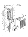
- a preferred embodiment of a filtering apparatus includes a thickener tank 1 having a suspension compartment 2 and a filtrate compartment 3.
- a separation plate 4 separates the suspension compartment 2 from the filtrate compartment 3.
- the separation plate 4 contains a plurality of approximately equally spaced holes or sockets 31 into each of which is placed a filter unit 5.
- Each filter unit 5 is suspended by a collar 6 in the hole 31 of the separation plate 4.
- Each collar 6 has a gasket 7 and is attached by bolts 8 to the separation plate 4 to ensure that there is no leakage of liquid between the filtrate compartment 3 and the suspension compartment 2 around the collars 6.
- the filtrate compartment 3 is provided with a filtrate overflow pipe 9 which is spaced a predetermined distance above the separation plate 4 in order to provide adequate backwash fluid and backwash pressure for the system.
- the vertical distance between the separation plate 4 and the lower end of the suspension compartment 2 is substantially greater than the length of each of the filter units 5, to provide a space in the lower portion of the suspension compartment 2 as a receiver portion for the accumulation of filter cake.
- the bottom of the receiver portion in the suspension compartment 2 is in the shape of a funnel 32 which is connected to an underflow pipe 10.
- a mechanized valve 11 controls the outflow of consolidated filter cake material through the underflow pipe 10.
- a supply pipe 12 supplies the liquid-solids suspension that is to be thickened into a holding tank 13.
- the suspension is pumped from the holding tank 13 by a first centrifugal pump 14 through a centrifugal pump outlet pipe 15 and into the suspension compartment 2.
- a second valve 80 may be provided in the centrifugal pump outlet pipe 15.
- the second valve 80 may be used to block the flow of suspension through the centrifugal pump outlet pipe 15 during the time that the valve 11 at the bottom of the thickener tank 1 is opened.
- the centrifugal pump 14 may be deactivated until the second valve 80 opens again.
- Each filter unit 5 has a rigid pipe 16 which is closed at the bottom and open at the top and connected to the collars 6 by which it is suspended on the separation plate 4.
- the rigid pipe 16 has a plurality of perforations 17.
- Each perforated pipe 16 is surrounded by a filter cloth sleeve 18 which may be held in place by two strips 19 positioned at the bottom and the top edge of the rigid pipe 16.
- Each of the strips 19 may be tightened by the use of a strip fastener 68, Figure 2.
- the filter cloth 18 rests on or is stretched against the rigid pipe 16 which acts to support and prevent bursting of the filter cloth 18 under filtration pressure.
- a loose-fitting accumulator grating 20, Figure 1 surrounds the filter cloth 18 over the full length of the perforated pipe 16.
- the accumulator grating 20 may be fastened on the filter unit 5 by fasteners 67, Figure 3, or other suitable means.
- the accumulator grating 20 acts to accumulate and grip the filter cake during the backwash phase of the process and to prevent bursting of the filter cloth under backwash pressure.
- the distance between the perforated pipes 16 and the accumulator grating 20 is approximately the thickness of the filter cloth 18 and the anticipated filter cake to avoid tensioning the filter cloth.
- the pressure created in the suspension compartment 2 by the first centrifugal pump 14 is higher than the pressure within the filter units 5.
- This pressure difference forces the filter cloth 18 against the rigid pipe or support pipe 16 and causes the liquid portion of the suspension to flow from the outside to the inside of each filter unit. Filtrate passes through the filter cloth and through the perforations in the support pipe 16 and flows upwardly into the filtrate compartment. The solids from the suspension adhere to the filter cloth 18 to form the filter cake.
- a sufficient depth of filter cake has accumulated on the suspension side of the filter cloth 18, a rapid reversal of pressures on the suspension and filtrate side causes the filter cloth to flop across the space provided between the support pipe 16 and the accumulator grating 20.
- the filter cloth 18 is pressed against the accumulator grating 20 and the filter cake which is formed on the filter cloth is thus squeezed into the spaces on the accumulator grating and held therein.
- the pressure on the suspension side may now be raised to cause a return flop of the filter cloth 18. It has been found that the filter cake remains impinged on the accumulator grating 20 and the filter cloth 18 flops back in a clean condition.
- the gripping action of the accumulator grating 20 reduces the backwash requirement to a minute film of water while allowing complete disengagement of the filter cake from the filter cloth 18. With this system, no waiting period is required for the filter cake to fall away from the filter cloth.
- the return flop is unimpeded by the presence of filter cake impinged on the accumulator grating 20 because as soon as the pressure in the suspension compartment 2 is raised, the filter cake in a few of the openings in the accumulator grating which were clogged with filter cake is ejected through or washed through the accumulator grating.
- the pressurized suspension immediately finds its way through these few openings and pushes back the filter cloth 18 against the support pipe 16, and the cycle is repeated.
- the filter units 5 of Figure 1 would be most useful in cases where the filter cake.is thin, lightweight, soft and cohesive and therefore tends to adhere to the filter cloth.
- the rigid pipe or support screen 16 and the accumulator grating 20 are spaced apart at least a distance approximating the thickness of the anticipated filter cake.
- the support screen 16 may consist of punched metal, or rigid bars of woven mesh or any other support system which is used in the industry
- the accumulator grating 20 should preferably be of a rigid, deeper construction to enmesh and retain the filter cake. Expanded sheet metal has been used very successfully for the purpose.
- the openings in the accumulator grating 20 may be 100mm 2 to 500mm 2 , for example.
- the twisted components of this mesh act as excellent gripping surfaces for the filter cake.
- several contiguous layers of woven mesh could also be used.
- the centrifugal pump 14 pumps the liquid-solids suspension from the tank 13 into the suspension compartment 2, creating a high pressure therein, since the compartment 2 is closed and fluid can flow out of the compartment only through the filter units 5.
- the liquid is forced through the filter cloth to the interior of the perforated pipe 16, and the solids accumulate on an outer surface of the filter cloth 18 as filter cake.
- the size of the filter cloth openings would determine the clarity of the liquid which becomes filtrate when it passes through the filter cloth 18.
- the filtrate then flows up into the filtrate compartment 3 and accumulates in that compartment until its level reaches the overflow pipe 9 which then removes the filtrate for further use in the mining operation, or for other purposes.
- the high pressure of the suspension keeps the filter cloth 18 pressed against the perforated support pipe 16.
- valve 11 at the bottom of the thickener tank 1 may be opened to remove some of the filter cake which has accumulated in the receiver portion at the bottom of the suspension compartment 2 during previous cycles. Opening this valve 11 will accelerate the downward flow of the filtrate which accelerates, in turn, the commencement of the backwash cycle.
- the filtrate retained in the filtrate compartment 3 flows back down the perforated pipes 16 to initiate the backwash cycle forcing the filter cloth away from the perforated pipes 16 and expanding the filter cloth 18 outwardly against the accumulator grating 20.
- the filter cake on the filter cloth 18 is thus squeezed into the spaces of, and is gripped by, the accumulator grating 20.
- the centrifugal pump 14 is again started and the pressure in the suspension compartment rises again.
- the filter cloth 18 flops back against the perforated pipe 16 leaving the filter cake on the accumulator grating 20.
- a second valve 80 may shut off flow to and from the centrifugal pump outlet pipe 15. With the valve 11 open and the second valve 80 closed, the suspension will flow towards the bottom of the thickener tank 1 instead of back through the centrifugal pump 14. The flow of suspension towards the bottom of the thickener tank 1 will also cause a downward flow of the filtrate from the filtrate compartment 3 to initiate the backwash cycle. After the backwash cycle is completed, as explained in the preceding paragraphs, the second valve 80 is opened and the valve 11 is closed. After restart of the first centrifugal pump 14, the pressure in the suspension compartment 2 will again rise and the filtration process will resume.
- the accumulator grating fills to capacity with filter cake and the excess filter cake which has been squeezed all the way through the accumulator grating 20 falls down to the bottom of the suspension compartment 2.
- the filter cake is allowed to accumulate at the bottom of the suspension compartment 2 and thus to consolidate over a substantial depth in the lower portion of the suspension compartment before a quantity is extruded periodically through the underflow pipe 10 when the valve 11 is open.
- the valve 11 is preferably either completely open or completely closed and is not kept in a partially open position.
- the thickener tank 1 is preferably of substantial height and because it preferably has a relatively small diameter the lumps of filter cake which have fallen to the bottom of the suspension compartment 2 are easily extruded by the substantial hydrostatic head at the bottom of the thickener tank 1.
- This arrangement avoids the necessity of having to rake or mechanically remove the filter cake as is required in the conventional thickening systems.
- the rate of removal of the lumps of filter cake together with some of the suspension which is inevitably trapped between the lumps of filter cake will determine the thickening which can be achieved.
- the lumps of filter cake may be allowed to accumulate at the bottom of the suspension compartment 2 so that they will be compressed by their own weight into a more dense mass. This will expel upwards some of the suspension fluid trapped between the filter cake lumps thus achieving a higher effective thickening.
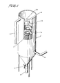
- a modified form of the filter unit 5' has the rigid perforated pipe 16 with the plurality of perforations or holes 17 therein.
- the filter cloth sleeve 18 is disposed over the perforated pipe 16 and the filter cloth is secured by a pair of support straps 19 to the perforated pipe 16.
- the filter cloth 18 has been separated into a plurality of filtering areas 26 by a plurality of fluid impermeable bands or strips 27.
- the filter cloth is sealed along these bands or strips 27 to provide a pattern of filtering areas which could be square, rectangular, triangular or any other two-dimensional area.
- the filter cake will then form only on the filtering areas 26 because the bands 27 are fluid impermeable.
- the bands 27 facilitate filter cake disengagement from the filter cloth 18 during backwash.
- the filter cloth 18 may be surrounded by an accumulator grating 20 (not illustrated).
- Filter cake is prevented from forming on top of the sealed strips 27 and therefore the cake can only form over the filtering areas on the surface of the cloth 18. Disengagement is thereby facilitated because the cake pieces are small and can immediately start sliding down the filter cloth 18 as the backwash cycle commences. There is no impediment to the initial sliding of the cakes because each filter cake piece is surrounded by a clear and narrow margin without'filter cake. The filter cake does not have to be broken up and pushed outwardly by the backwash as would happen if the filter cloth 18 were covered by one large surface of continuous filter cake.
- This version of the filter cloth operates very effectively with a tailing suspension comprised of a coarse gradation of solids which forms a tough, thick and heavy filter cake. The filter cake pieces, being heavier than the suspension, once disengaged from the filter cloth 18, will fall through the suspension to the bottom of the suspension compartment 2 from where they can be withdrawn.
- the filter cloth 18 can be sealed, for example, by the application of a somewhat flexible paint which can be coated along narrow 13mm to 16mm bands to form, for example, square grids of 152mm by 152mm.
- a somewhat flexible paint which can be coated along narrow 13mm to 16mm bands to form, for example, square grids of 152mm by 152mm.
- other ways of creating the sealed narrow bands such as impervious tape and other widths and other pattern shapes and sizes could naturally be used for the same purpose.
- An accumulator grating 20 may be also used with the filter unit 5'. Because the strips 27 are impermeable and will prevent any filter cake from accumulating over themselves, the accumulator grating 20 will always be free of filter cake opposite these treated strips or areas. The suspension can thus readily flow through the accumulator grating 20 at these locations to begin the next filtration cycle.
- a second modified form of the filter unit 5 11 has a corrugated perforated pipe 33 which is surrounded by a filter cloth sleeve 18.
- the perforated pipe 33 is corrugated in order to avoid stretching the filter cloth 18 during its flopping action. Thus the filter cloth 18 is prevented from being expanded against the larger diameter accumulator grating 20.
- the perforated pipe 33 which serves as the support screen is preferably shaped to be vertically corrugated over a central portion of its length as shown in Figure 5.
- the end portions of the perforated pipe 33 are not corrugated, see Figure 4. It has been found that horizontal corrugations will not perform adequately, rather, the corrugations should be substantially vertical or at least spiral. In other words, the corrugations must have a vertical component.
- FIG 5 are designed so that the perimeter distance along the surface of the perforated pipe 33 is substantially the same as the inside perimeter distance of the accumulator grating 20.
- the perforated pipe 33 is preferably made of a perforated metal which is rolled and then spot-welded.
- a modified form of thickener tank 1 1 includes a suspension compartment 2', a first filtrate compartment 41 and a second filtrate compartment 42.
- a second centrifugal pump 43 is located between the two filtrate compartments 41, 42.
- the second centrifugal pump 43 is mounted on a second separating plate 70 which is secured to the thickener tank 1 1 .
- the second centrifugal pump 43 pumps filtrate, preferably a non-abrasive clear liquid, from the second filtrate compartment 42 down into the first filtrate compartment 41.
- the backwash pressure in the first filtrate compartment 41 exceeds the pressure normally developed by the first centrifugal pump 14 through the centrifugal pump outlet pipe 15 in the suspension compartment 2'.
- the second centrifugal pump 43 is stopped and the line pressure through the first centrifugal pump outlet pipe 15 again raises the pressure in the suspension compartment 2 to commence filtrate production.
- the filtrate flows from the inside of each filter unit 5 into the first filtrate compartment 41 and hence through the non-operating second centrifugal pump 43 and into the second filtrate compartment 42.
- the filtrate accumulates until it reaches the overflow pipe 9 which removes the filtrate from the thickener tank 1'.
- the filter cloth sleeve 18 for any of the above- described embodiments may be obtained from the Barrday division of Wheelabrator Corporation of Canada Limited located in Cambridge, Ontario and in Montreal, Quebec.
- a typical filter cloth material is style number fn2080 which is a 2/2 weave nylon fabric weighing 495 g/m 2 .
- Another typical filtration cloth is style number f3030 which is a plain weave terylene fabric weighing 136 g/m 2 .
- a United States company which manufactures filter cloth is Albany International Technical Fabrics Division 1400 Clinton Street Buffalo New York 14206.
- the preferred embodiment of the filter unit 5 may be 203mm to 305mm in diameter and is 3.66m to 6.1m long although lengths over 6.1m may be used.
- the perforations in the perforated pipes 16, 33 may be located 6.4mm away from each other and may be 3.2mm in diameter.
- a preferred thickener tank 1 may be 3.66m in diameter and 9.14m to 12.2m high.
- the filtrate overflow pipe 9 is disposed at least 0.6m above the separation plate 4 which separates the filtrate compartment 3 from the suspension compartment 2 although, as much as 2.4m or more of filtrate could be disposed in the filtrate compartment to provide the hydrostatic head used during the backwash cycle. That is, the filtrate overflow pipe 9 could be located 2.44m above the separation plate 4. The system does not need a rake at the bottom because of the pressure exerted by the hydrostatic head on the filter cake disposed in the funnel 32.
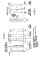
- a pressure cycle for a 6.1m long filter unit 5 in a thickener tank 1 having a 0.6m overflow can be calculated.
- the filtrate is water.
- the suspension pressure outside the filter unit 5 is calculated on the basis of a 50% solids by weight mixture having a specific gravity of the solids of 3. Therefore, the unit weight of the suspension is 1498 kg/m 3 .
- the pump or line pressure is assumed to be 172.4 kPa.
- the pressure of the clear filtrate or water inside the filter tube varies from zero at the point of overflow 0.6m above the filter unit 5, to -65.7 kPa at the bottom of the filter unit (the negative sign is used for those pressures that oppose filtrate and filter cake production but aid the backwash cycle).
- the pressure of the filtrate is -6 kPa.
- the suspension pressure at the top of the filter unit is zero, and increases linearly so that at the bottom it is 89.6 kPa.
- the net filtration pressure at the top of the filter unit is 166.4 kPa whereas the pressure at the bottom is 196.3 kPa during the pressure cycle.
- a backwash cycle for 6.1 m long filter unit 5 having a 0.6 m overflow and a suspension level in holding tank 13 located 3.66m from the top of the 6.1m long filter unit may be calculated.
- the clear filtrate water pressure inside the filter unit during the backwash cycle would drop at the top of the filter unit from -6 kPa at the start of the backwash cycle to zero at the end of the cycle, whereas at the bottom the corresponding water pressure would drop from -65.7 kPa to -59.7 kPa.
- the suspension pressure is -53.8 kPa at the top of the filter unit and 35.8 kPa at the bottom of the filter unit.
- the net backwash pressure thus ranges from -59.8 kPa to -53.8 kPa at the top of the filter unit 5 and is in the range of -29.9 kPa to -23.9 kPa at the bottom of the filter unit.
- the backwash pressure is not uniform over the height of the filter unit 5, this differential is not of much concern because both pressures are negative. All that is required to commence the backwash cycle is that a negative pressure be exerted at all points from inside the filter unit 5 to outside the filter unit to push the filter cloth 18 outwardly.
Abstract
Description
- The invention relates to filtering apparatus and methods of filtering a liquid-solids suspension, and more particularly, to filtration thickening methods and apparatus which can be used, for example, in ore processing and tailing thickening operations in the mining industry.
- In mining operations, water, with and without chemical additives, is commonly used to separate the ore from the finely crushed rock and earth particles. All matter that is not ore is known as mine tailing and it is by far the largest portion of material involved in the operations. Mine tailing has no commercial value and is disposed of with a considerable amount of process water in large man-built tailing ponds provided for this purpose. In order to reduce the cost of recycling the process water and also to reduce the size and hence the cost of the tailing ponds and tailing conveyance equipment it is common practice to remove as much process water as possible before conveying the waste solids to the disposal pond. A method currently in use for this purpose is to pass the tailing through settlement basins known as thickeners which may be as large as 137 m in diameter. As the solid particles settle by gravity on the bottom of the basin, a rake pushes the particles toward an outlet at the center of the basin. The mixture of collected solids together with the process water that escapes through this outlet is known as tailing underflow. The underflow is pumped from the center outlet to the tailing pond, Clear water flows over the top of the wall around the perimeter of the basin, and is recovered as process water for recycling. The cost of building and operating basin thickeners can be very high. Furthermore, such gravity sedimentation-type basin thickeners can generally thicken the tailing to only 10 to 50% solids by weight, whereas it would be desirable to achieve values of 30 to 75% solids, respectively, the value being dependent on the type of tailing. Therefore a considerable amount of water still remains with the tailing. The use of chemical flocculants in such machinery is used to increase the rate of sedimentation but it has little effect on the final concentration of solids in the underflow.
- In the known filtration thickening apparatus, the suspension of solids that is to be thickened is introduced to one side of a filter cloth. The perforations of the filter cloth are sized to allow the passage of the liquid component of the suspension, but to prevent the passage of the solids component. Most filter-cloths consist of a woven fabric, commonly made of synthetic fibers, either loosely or tightly woven, as determined by the grain size of the suspended solids and by the desired clarity of the resulting filtrate.
- A known way of forcing liquid through the filter-cloth is to raise the pressure of the suspension to a higher value than the pressure of the filtrate on the opposite side of the filter cloth. Another known way of forcing liquid through the filter cloth is by applying a suction or vacuum on the filtrate side of the filter cloth. As the liquid flows through the filter-cloth, the suspended solids impinge on it, developing thereon a layer of solids known as filter cake. As the filter cake thickness grows, the passage of liquid through the filter-cloth is impeded. In order to clear the filter cloth at specific intervals of time or at specific pressure differentials that are eventually reached between the suspension and filtrate sides, the pressure differential on the two sides of the filter cloth is reversed. This causes a reversal in the flow of liquid and therefore some of the filtrate is forced to return to the suspension side. In so doing, the filtrate disengages the accumulated filter cake which then settles in the form of sheets and strips through the suspension compartment to the bottom of the equipment from where the thickened suspension can be withdrawn. This is commonly termed the backwash cycle.
- Because the filter cloth is not normally strong enough to withstand the desirable filtration pressure, nor in some cases the desired backwash pressure, it is common practice to provide supports means on either one or both sides of the filter cloth. These support means generally consist of rigid cages, screens, or perforated plates. The supports allow the passage of liquid but prevent the filter cloth from bursting.
- Suspensions from different industrial processes vary chemically, and in both size and shape of the particles that form their solids component. It can therefore be reasonably expected that various filter cakes will differ in their thicknesses, weights, toughnesses and the facility with which they disengage from the filter cloth. A particular filter cake may be very soft and light, such as results from filter thickening of natural clay slimes, a waste product from the processing of phosphate ore. On the other hand, the filter cake may be relatively dry, heavy and tough such as the product of filter thickening of tailing waste from base metal mining operations. It has been found that the gradation and specific gravity of the solids play a primary role in the ease or difficulty with which filter cake can be disengaged from the filter cloth. Generally, the coarser the fraction, the easier the build up of filter cake on the filter cloth and thus the easier the disengagement of the filter cake from the filter cloth. To be commercially practical, the filter or thickener apparatus must be capable of operating effectively and efficiently with a soft and light filter cake, or with a coarse filter cake, the apparatus being designed as required to suit one or several of the various industrial processes.
- One major drawback of known filter thickeners is that a very large quantity of backwash filtrate or cleansing liquid is required to disengage the filter cake from the cloth and to clean the filter cloth to permit the cycle to be repeated.
- The more backwash liquid that is used, the less efficient becomes the system, the efficiency being measured by the net gain of filtrate over the filtrate lost during the backwashing cycle. It has been proposed to utilize continuous processes having multiple tubular filter elements which operate sequentially. However, these continuous processes do not obviate the problem of large losses of fluid during the backwash cycle of any filter element.
- It is therefore an object of the present invention to provide a method and apparatus for efficient filtration and thickening of tailing to reduce the cost of disposal.
- It is a further object of this invention to provide a method and apparatus for removing liquid from a slurry or solids suspension at a high flow rate while being relatively inexpensive to construct and operate.
- It is yet another object of the present invention to provide a method and apparatus for drawing water from tailing at a high flow rate that requires a relatively small area of space for the apparatus, is simple to construct and operate, and has a minimum of moving parts.
- It is still another object of the present invention to provide several filtering methods and apparatuses designed for the various types of filter cake encountered in filtration.
- According to the invention there is provided filtering apparatus comprising tank means including a receiver for filter cake, filter means in said tank means including a filter cloth, supply means for supplying a liquid-solids suspension to said tank means on one side of said filter means and a filtrate compartment for receiving filtrate passing through to the other side of said filter means, whereby during the filtering process the liquid of the liquid-solids suspension flows from the supply means through the filter means and provides a reverse flow to backwash the filter means and dislodge filter cake.
- The invention also comprehends a method of filtering a liquid-solids suspension comprising pumping the suspension into a suspension compartment,forcing a liquid portion of the suspension through a filter cloth by pressurizing the suspension in said suspension compartment such that the liquid portion of the suspension flows through said filter cloth to become filtrate and a solids portion of the suspension collects on said filter cloth as filter cake, intermittently backwashing the liquid portion in a reverse direction through said filter cloth to force the solids portion to intrude into and adhere to a first side of an accumulator grating, and intermittently extruding the solids portion accumulated in said grating through a second side of said accumulator grating by the pressure of the solids portion deposited during subsequent cycles.
- Filtration thickening apparatus according to a preferred embodiment of the present invention includes a thickener tank to which the tailing or other liquid-solid suspension is supplied. The tank has a receiver portion at the bottom for the accumulation of filter cake and a filtrate compartment at the top for collection of filtrate. Individual tubular filter units are suspended in the tank below the filtrate compartment and above the filter cake receiver portion. An overflow pipe is spaced above the filter units in the filtrate compartment for draining the filtrate liquid from the tank.
- A supply pipe enters the tank above the filter cake receiver portion. The filter units preferably include either an accumulator grating or a filter cloth which is sealed along narrow bands to form a pattern of filtering areas or both.
- A centrifugal pump supplies the tailing from a holding tank to the thickener tank and a valve controls the discharge of filter cake from the receiver portion of the thickener tank.
- The process of filtration thickening a liquid-solids suspension in accordance with a preferred embodiment of the present invention includes pumping the suspension into a thickener tank. The liquid portion of the suspension is forced to flow through the filter cloth as filtrate and the solids portion collects on the filter cloth as filter cake. The filter cloth preferably is separated into filtering areas by liquid impermeable strips to improve the sloughing off of the filter cake during backwashing. A portion of the filtrate is intermittently backwashed to slough off the solids portion from the filter cloth. A centrifugal pump supplies the tailing to the thickener tank, forcing the liquid through the filter units and upwardly to a filtrate compartment from which the clarified liquid is discharged by gravity. Backwashing is accomplished by stopping the pump and simultaneously opening the underflow valve to discharge a portion of the filter cake underflow which has accumulated in the receiver portion of the tank. As soon as the pump is stopped the hydrostatic head of the suspension in the thickener tank causes part of the suspension to drain back through the pump and into a holding tank which is disposed at a lower elevation. This action, together with the discharge of some filter cake underflow, creates a lower head in the thickener tank suspension than in the clarified liquid filtrate compartment, thus filtrate flow is reversed. Reversed flow from the filtrate compartment causes the clarified liquid to flow through the filter units in the reverse direction, thereby dislodging the filter cake and causing it to fall into the receiver at the bottom of the tank from whence it will be removed by the opening of the underflow valve in subsequent backwash cycles. The process can be repeated at time intervals as selected according to the rate at which the filter cake builds up on the filter units.
- Some embodiments of the invention are described in detail below, by way of example, with reference to the accompanying drawings, in which:-
- Figure 1 is an isometric view, partially in cross-section, of a preferred embodiment of filtering apparatus according to the present invention,
- Figure 2 is a side view, partially in cross-section, of a modified form of a filter unit according to the present invention,
- Figure 3 is a side view, partially in cross-section, of a second modified form of the filter unit according to the present invention,
- Figure 4 is a cross-sectional view of the filter unit of Figure 3 along line 4-4 in Figure 3,
- Figure 5 is a cross-sectional view of the filter unit of Figure 3 along line 5-5 in Figure 3,
- Figure 6 is an isometric view, partially in cross-section, of a modified form of a thickener tank for filtering apparatus of the present invention,
- Figure 7 is a diagram of pressure versus elevation during a pressure cycle of the filtering apparatus of the present invention, and
- Figure 8 is a diagram of pressure versus elevation during a backwash cycle of the filtering apparatus of Figure 7.
- In the drawings like members bear like reference numerals.
- With reference to Figure 1, a preferred embodiment of a filtering apparatus according to the present invention includes a thickener tank 1 having a
suspension compartment 2 and afiltrate compartment 3. Aseparation plate 4 separates thesuspension compartment 2 from thefiltrate compartment 3. Theseparation plate 4 contains a plurality of approximately equally spaced holes orsockets 31 into each of which is placed afilter unit 5. Eachfilter unit 5 is suspended by acollar 6 in thehole 31 of theseparation plate 4. Eachcollar 6 has a gasket 7 and is attached bybolts 8 to theseparation plate 4 to ensure that there is no leakage of liquid between thefiltrate compartment 3 and thesuspension compartment 2 around thecollars 6. - The
filtrate compartment 3 is provided with afiltrate overflow pipe 9 which is spaced a predetermined distance above theseparation plate 4 in order to provide adequate backwash fluid and backwash pressure for the system. The vertical distance between theseparation plate 4 and the lower end of thesuspension compartment 2 is substantially greater than the length of each of thefilter units 5, to provide a space in the lower portion of thesuspension compartment 2 as a receiver portion for the accumulation of filter cake. The bottom of the receiver portion in thesuspension compartment 2 is in the shape of a funnel 32 which is connected to anunderflow pipe 10. A mechanized valve 11 controls the outflow of consolidated filter cake material through theunderflow pipe 10. - A
supply pipe 12 supplies the liquid-solids suspension that is to be thickened into a holdingtank 13. The suspension is pumped from the holdingtank 13 by a firstcentrifugal pump 14 through a centrifugalpump outlet pipe 15 and into thesuspension compartment 2. - In an alternate embodiment, a
second valve 80 may be provided in the centrifugalpump outlet pipe 15. Thesecond valve 80 may be used to block the flow of suspension through the centrifugalpump outlet pipe 15 during the time that the valve 11 at the bottom of the thickener tank 1 is opened. When thesecond valve 80 has closed the centrifugalpump outlet pipe 15, thecentrifugal pump 14 may be deactivated until thesecond valve 80 opens again. - Four
filter units 5 are provided in the thickener tank, although only three units are visible in Figure 1. However, the number of filter units that can be accommodated is only dependent upon the size of the thickener tank 1 and the diameter of each of thefilter units 5. Eachfilter unit 5 has arigid pipe 16 which is closed at the bottom and open at the top and connected to thecollars 6 by which it is suspended on theseparation plate 4. Therigid pipe 16 has a plurality ofperforations 17. Eachperforated pipe 16 is surrounded by afilter cloth sleeve 18 which may be held in place by twostrips 19 positioned at the bottom and the top edge of therigid pipe 16. Each of thestrips 19 may be tightened by the use of astrip fastener 68, Figure 2. Thefilter cloth 18 rests on or is stretched against therigid pipe 16 which acts to support and prevent bursting of thefilter cloth 18 under filtration pressure. - A loose-fitting accumulator grating 20, Figure 1, surrounds the
filter cloth 18 over the full length of theperforated pipe 16. The accumulator grating 20 may be fastened on thefilter unit 5 byfasteners 67, Figure 3, or other suitable means. The accumulator grating 20 acts to accumulate and grip the filter cake during the backwash phase of the process and to prevent bursting of the filter cloth under backwash pressure. _The distance between theperforated pipes 16 and the accumulator grating 20 is approximately the thickness of thefilter cloth 18 and the anticipated filter cake to avoid tensioning the filter cloth. - During the filter process the pressure created in the
suspension compartment 2 by the firstcentrifugal pump 14 is higher than the pressure within thefilter units 5. This pressure difference forces thefilter cloth 18 against the rigid pipe orsupport pipe 16 and causes the liquid portion of the suspension to flow from the outside to the inside of each filter unit. Filtrate passes through the filter cloth and through the perforations in thesupport pipe 16 and flows upwardly into the filtrate compartment. The solids from the suspension adhere to thefilter cloth 18 to form the filter cake. When a sufficient depth of filter cake has accumulated on the suspension side of thefilter cloth 18, a rapid reversal of pressures on the suspension and filtrate side causes the filter cloth to flop across the space provided between thesupport pipe 16 and the accumulator grating 20. Thefilter cloth 18 is pressed against the accumulator grating 20 and the filter cake which is formed on the filter cloth is thus squeezed into the spaces on the accumulator grating and held therein. The pressure on the suspension side may now be raised to cause a return flop of thefilter cloth 18. It has been found that the filter cake remains impinged on the accumulator grating 20 and thefilter cloth 18 flops back in a clean condition. The gripping action of the accumulator grating 20 reduces the backwash requirement to a minute film of water while allowing complete disengagement of the filter cake from thefilter cloth 18. With this system, no waiting period is required for the filter cake to fall away from the filter cloth. - The return flop is unimpeded by the presence of filter cake impinged on the accumulator grating 20 because as soon as the pressure in the
suspension compartment 2 is raised, the filter cake in a few of the openings in the accumulator grating which were clogged with filter cake is ejected through or washed through the accumulator grating. The pressurized suspension immediately finds its way through these few openings and pushes back thefilter cloth 18 against thesupport pipe 16, and the cycle is repeated. - The
filter units 5 of Figure 1 would be most useful in cases where the filter cake.is thin, lightweight, soft and cohesive and therefore tends to adhere to the filter cloth. The rigid pipe orsupport screen 16 and the accumulator grating 20 are spaced apart at least a distance approximating the thickness of the anticipated filter cake. Whereas thesupport screen 16 may consist of punched metal, or rigid bars of woven mesh or any other support system which is used in the industry, the accumulator grating 20 should preferably be of a rigid, deeper construction to enmesh and retain the filter cake. Expanded sheet metal has been used very successfully for the purpose. The openings in the accumulator grating 20 may be 100mm2 to 500mm2, for example. The twisted components of this mesh act as excellent gripping surfaces for the filter cake. Alternatively, several contiguous layers of woven mesh could also be used. - In operation, the
centrifugal pump 14 pumps the liquid-solids suspension from thetank 13 into thesuspension compartment 2, creating a high pressure therein, since thecompartment 2 is closed and fluid can flow out of the compartment only through thefilter units 5. As the suspension is forced against thefilter cloth 18, the liquid is forced through the filter cloth to the interior of theperforated pipe 16, and the solids accumulate on an outer surface of thefilter cloth 18 as filter cake. The size of the filter cloth openings would determine the clarity of the liquid which becomes filtrate when it passes through thefilter cloth 18. The filtrate then flows up into thefiltrate compartment 3 and accumulates in that compartment until its level reaches theoverflow pipe 9 which then removes the filtrate for further use in the mining operation, or for other purposes. During the production of filtrate, the high pressure of the suspension keeps thefilter cloth 18 pressed against theperforated support pipe 16. - When the filter cake has developed to a reasonable thickness or when the production of filtrate slows, due to the obstructing presence of an ever-thickening filter cake, the
centrifugal pump 14 is stopped. The pressure in thesuspension compartment 2 drops immediately because the hydraulic head supplied by the pump ceases. The suspension flows back through thepump 14 into the holdingtank 13 because the level of the suspension in theholding tank 13 is lower than the level of .--he filtrate in thefiltrate compartment 3. This flow cf suspension causes the filtrate to flow back through thefilter units 5 and dislodges the filter cake. The intensity of the backwash pressure acting over the length of eachfilter unit 5 is determined by the difference in levels of the liquid in theholding tank 13 and thefiltrate compartment 3. The backwash process takes 2 to 15 seconds. - At the same time that the
centrifugal pump 14 is stopped the valve 11 at the bottom of the thickener tank 1 may be opened to remove some of the filter cake which has accumulated in the receiver portion at the bottom of thesuspension compartment 2 during previous cycles. Opening this valve 11 will accelerate the downward flow of the filtrate which accelerates, in turn, the commencement of the backwash cycle. The filtrate retained in thefiltrate compartment 3 flows back down theperforated pipes 16 to initiate the backwash cycle forcing the filter cloth away from theperforated pipes 16 and expanding thefilter cloth 18 outwardly against the accumulator grating 20. The filter cake on thefilter cloth 18 is thus squeezed into the spaces of, and is gripped by, the accumulator grating 20. As soon as this happens, thecentrifugal pump 14 is again started and the pressure in the suspension compartment rises again. As the pressure in thesuspension compartment 2 rises thefilter cloth 18 flops back against theperforated pipe 16 leaving the filter cake on the accumulator grating 20. - Alternatively, at the same time as the valve 11 at the bottom of the thickener tank 1 is opened, a
second valve 80 may shut off flow to and from the centrifugalpump outlet pipe 15. With the valve 11 open and thesecond valve 80 closed, the suspension will flow towards the bottom of the thickener tank 1 instead of back through thecentrifugal pump 14. The flow of suspension towards the bottom of the thickener tank 1 will also cause a downward flow of the filtrate from thefiltrate compartment 3 to initiate the backwash cycle. After the backwash cycle is completed, as explained in the preceding paragraphs, thesecond valve 80 is opened and the valve 11 is closed. After restart of the firstcentrifugal pump 14, the pressure in thesuspension compartment 2 will again rise and the filtration process will resume. - As either of these processes is repeated, the accumulator grating fills to capacity with filter cake and the excess filter cake which has been squeezed all the way through the accumulator grating 20 falls down to the bottom of the
suspension compartment 2. The filter cake is allowed to accumulate at the bottom of thesuspension compartment 2 and thus to consolidate over a substantial depth in the lower portion of the suspension compartment before a quantity is extruded periodically through theunderflow pipe 10 when the valve 11 is open. The valve 11 is preferably either completely open or completely closed and is not kept in a partially open position. - Because the thickener tank 1 is preferably of substantial height and because it preferably has a relatively small diameter the lumps of filter cake which have fallen to the bottom of the
suspension compartment 2 are easily extruded by the substantial hydrostatic head at the bottom of the thickener tank 1. This arrangement avoids the necessity of having to rake or mechanically remove the filter cake as is required in the conventional thickening systems. The rate of removal of the lumps of filter cake together with some of the suspension which is inevitably trapped between the lumps of filter cake will determine the thickening which can be achieved. To reduce the amount of trapped suspension being removed and thereby increase the effect of thickening, the lumps of filter cake may be allowed to accumulate at the bottom of thesuspension compartment 2 so that they will be compressed by their own weight into a more dense mass. This will expel upwards some of the suspension fluid trapped between the filter cake lumps thus achieving a higher effective thickening. - With reference now to Figure 2, a modified form of the
filter unit 5' has the rigidperforated pipe 16 with the plurality of perforations or holes 17 therein. Thefilter cloth sleeve 18 is disposed over theperforated pipe 16 and the filter cloth is secured by a pair of support straps 19 to theperforated pipe 16. Thefilter cloth 18 has been separated into a plurality offiltering areas 26 by a plurality of fluid impermeable bands or strips 27. The filter cloth is sealed along these bands or strips 27 to provide a pattern of filtering areas which could be square, rectangular, triangular or any other two-dimensional area. The filter cake will then form only on thefiltering areas 26 because thebands 27 are fluid impermeable. Thebands 27 facilitate filter cake disengagement from thefilter cloth 18 during backwash. Thefilter cloth 18 may be surrounded by an accumulator grating 20 (not illustrated). - Filter cake is prevented from forming on top of the sealed strips 27 and therefore the cake can only form over the filtering areas on the surface of the
cloth 18. Disengagement is thereby facilitated because the cake pieces are small and can immediately start sliding down thefilter cloth 18 as the backwash cycle commences. There is no impediment to the initial sliding of the cakes because each filter cake piece is surrounded by a clear and narrow margin without'filter cake. The filter cake does not have to be broken up and pushed outwardly by the backwash as would happen if thefilter cloth 18 were covered by one large surface of continuous filter cake. This version of the filter cloth operates very effectively with a tailing suspension comprised of a coarse gradation of solids which forms a tough, thick and heavy filter cake. The filter cake pieces, being heavier than the suspension, once disengaged from thefilter cloth 18, will fall through the suspension to the bottom of thesuspension compartment 2 from where they can be withdrawn. - The
filter cloth 18 can be sealed, for example, by the application of a somewhat flexible paint which can be coated along narrow 13mm to 16mm bands to form, for example, square grids of 152mm by 152mm. Of course other ways of creating the sealed narrow bands, such as impervious tape and other widths and other pattern shapes and sizes could naturally be used for the same purpose. - An accumulator grating 20 may be also used with the
filter unit 5'. Because thestrips 27 are impermeable and will prevent any filter cake from accumulating over themselves, the accumulator grating 20 will always be free of filter cake opposite these treated strips or areas. The suspension can thus readily flow through the accumulator grating 20 at these locations to begin the next filtration cycle. - With reference now to Figures 3 to 5 a second modified form of the
filter unit 511 has a corrugatedperforated pipe 33 which is surrounded by afilter cloth sleeve 18. - The
perforated pipe 33 is corrugated in order to avoid stretching thefilter cloth 18 during its flopping action. Thus thefilter cloth 18 is prevented from being expanded against the larger diameter accumulator grating 20. Theperforated pipe 33 which serves as the support screen is preferably shaped to be vertically corrugated over a central portion of its length as shown in Figure 5. The end portions of theperforated pipe 33 are not corrugated, see Figure 4. It has been found that horizontal corrugations will not perform adequately, rather, the corrugations should be substantially vertical or at least spiral. In other words, the corrugations must have a vertical component. The number of corrugations and the depth of thecorrugations 34, - Figure 5, are designed so that the perimeter distance along the surface of the
perforated pipe 33 is substantially the same as the inside perimeter distance of the accumulator grating 20. Thus thefilter cloth 18 remains unstressed whether it is being pressed inwardly against theperforated pipe 33 during filtrate and filter cake production or it is being pressed outwardly against the accumulator grating 20 during the backwash cycle. Theperforated pipe 33 is preferably made of a perforated metal which is rolled and then spot-welded. - With reference now to Figure 6, a modified form of thickener tank 11 includes a suspension compartment 2', a
first filtrate compartment 41 and asecond filtrate compartment 42. A secondcentrifugal pump 43 is located between the twofiltrate compartments centrifugal pump 43 is mounted on asecond separating plate 70 which is secured to the thickener tank 11. The secondcentrifugal pump 43 pumps filtrate, preferably a non-abrasive clear liquid, from thesecond filtrate compartment 42 down into thefirst filtrate compartment 41. When such pumping occurs, the backwash pressure in thefirst filtrate compartment 41 exceeds the pressure normally developed by the firstcentrifugal pump 14 through the centrifugalpump outlet pipe 15 in the suspension compartment 2'. This pressure difference creates the required backwash flow through thefilter cloth 18, not visible in Figure 6, as some suspension fluid is forced back through the centrifugalpump outlet pipe 15. Using this preferred embodiment, it might take 2 to 10 minutes to accumulate the filter cake and 2 to 15 seconds to backwash. - At the termination of the backwash cycle, the second
centrifugal pump 43 is stopped and the line pressure through the first centrifugalpump outlet pipe 15 again raises the pressure in thesuspension compartment 2 to commence filtrate production. The filtrate flows from the inside of eachfilter unit 5 into thefirst filtrate compartment 41 and hence through the non-operating secondcentrifugal pump 43 and into thesecond filtrate compartment 42. In thesecond filtrate compartment 42 the filtrate accumulates until it reaches theoverflow pipe 9 which removes the filtrate from the thickener tank 1'. - As a specific example for constructing and operating the apparatus of this invention the following components are suitable. The
filter cloth sleeve 18 for any of the above- described embodiments may be obtained from the Barrday division of Wheelabrator Corporation of Canada Limited located in Cambridge, Ontario and in Montreal, Quebec. A typical filter cloth material is style number fn2080 which is a 2/2 weave nylon fabric weighing 495 g/m2. Another typical filtration cloth is style number f3030 which is a plain weave terylene fabric weighing 136 g/m2. A United States company which manufactures filter cloth is Albany International Technical Fabrics Division 1400 Clinton Street Buffalo New York 14206. - The preferred embodiment of the
filter unit 5 may be 203mm to 305mm in diameter and is 3.66m to 6.1m long although lengths over 6.1m may be used. The perforations in theperforated pipes - As many as eighty
filter units 5 would fit into the preferred thickener tank 1. Preferably thefiltrate overflow pipe 9 is disposed at least 0.6m above theseparation plate 4 which separates thefiltrate compartment 3 from thesuspension compartment 2 although, as much as 2.4m or more of filtrate could be disposed in the filtrate compartment to provide the hydrostatic head used during the backwash cycle. That is, thefiltrate overflow pipe 9 could be located 2.44m above theseparation plate 4. The system does not need a rake at the bottom because of the pressure exerted by the hydrostatic head on the filter cake disposed in the funnel 32. - With reference now also to Figure 7, a pressure cycle for a 6.1m
long filter unit 5 in a thickener tank 1 having a 0.6m overflow can be calculated. Preferably, the filtrate is water. The suspension pressure outside thefilter unit 5 is calculated on the basis of a 50% solids by weight mixture having a specific gravity of the solids of 3. Therefore, the unit weight of the suspension is 1498 kg/m3. The pump or line pressure is assumed to be 172.4 kPa. The pressure of the clear filtrate or water inside the filter tube varies from zero at the point of overflow 0.6m above thefilter unit 5, to -65.7 kPa at the bottom of the filter unit (the negative sign is used for those pressures that oppose filtrate and filter cake production but aid the backwash cycle). At the top of the 6.1mlong filter unit 5, the pressure of the filtrate is -6 kPa. Naturally, the suspension pressure at the top of the filter unit is zero, and increases linearly so that at the bottom it is 89.6 kPa. Adding the pressures, the net filtration pressure at the top of the filter unit is 166.4 kPa whereas the pressure at the bottom is 196.3 kPa during the pressure cycle. - With reference now also to Figure 8, a backwash cycle for 6.1 m
long filter unit 5 having a 0.6 m overflow and a suspension level in holdingtank 13 located 3.66m from the top of the 6.1m long filter unit may be calculated. The clear filtrate water pressure inside the filter unit during the backwash cycle would drop at the top of the filter unit from -6 kPa at the start of the backwash cycle to zero at the end of the cycle, whereas at the bottom the corresponding water pressure would drop from -65.7 kPa to -59.7 kPa. The suspension pressure is -53.8 kPa at the top of the filter unit and 35.8 kPa at the bottom of the filter unit. The net backwash pressure thus ranges from -59.8 kPa to -53.8 kPa at the top of thefilter unit 5 and is in the range of -29.9 kPa to -23.9 kPa at the bottom of the filter unit. Although the backwash pressure is not uniform over the height of thefilter unit 5, this differential is not of much concern because both pressures are negative. All that is required to commence the backwash cycle is that a negative pressure be exerted at all points from inside thefilter unit 5 to outside the filter unit to push thefilter cloth 18 outwardly.
Claims (20)
Applications Claiming Priority (2)
| Application Number | Priority Date | Filing Date | Title |
|---|---|---|---|
| US06/292,737 US4436633A (en) | 1981-08-14 | 1981-08-14 | Filtration thickening method and apparatus |
| US292737 | 1981-08-14 |
Publications (3)
| Publication Number | Publication Date |
|---|---|
| EP0072672A2 true EP0072672A2 (en) | 1983-02-23 |
| EP0072672A3 EP0072672A3 (en) | 1984-08-01 |
| EP0072672B1 EP0072672B1 (en) | 1987-04-01 |
Family
ID=23125982
Family Applications (1)
| Application Number | Title | Priority Date | Filing Date |
|---|---|---|---|
| EP82304269A Expired EP0072672B1 (en) | 1981-08-14 | 1982-08-12 | Filtering apparatus and a method of filtering a liquid-solids suspension |
Country Status (17)
| Country | Link |
|---|---|
| US (1) | US4436633A (en) |
| EP (1) | EP0072672B1 (en) |
| JP (1) | JPS5840118A (en) |
| AU (1) | AU558554B2 (en) |
| BR (1) | BR8204760A (en) |
| CA (1) | CA1188626A (en) |
| DE (1) | DE3275911D1 (en) |
| ES (1) | ES514971A0 (en) |
| FI (1) | FI72048C (en) |
| GB (1) | GB2103952B (en) |
| IN (1) | IN158521B (en) |
| NO (1) | NO822753L (en) |
| NZ (1) | NZ201576A (en) |
| PT (1) | PT75426B (en) |
| ZA (1) | ZA825598B (en) |
| ZM (1) | ZM6482A1 (en) |
| ZW (1) | ZW16482A1 (en) |
Cited By (3)
| Publication number | Priority date | Publication date | Assignee | Title |
|---|---|---|---|---|
| EP0547512A1 (en) * | 1991-12-13 | 1993-06-23 | Eltech Systems Corporation | Crystallizer filter |
| WO1993020921A1 (en) * | 1992-04-14 | 1993-10-28 | Caustec Aktiebolag | Device for cleaning of caustic liquor mixtures |
| CN113171657A (en) * | 2021-03-11 | 2021-07-27 | 邵福生 | Road construction dust collector capable of avoiding secondary pollution |
Families Citing this family (23)
| Publication number | Priority date | Publication date | Assignee | Title |
|---|---|---|---|---|
| US4528103A (en) * | 1984-04-06 | 1985-07-09 | Dorr-Oliver Incorporated | Pressure filter |
| US4590994A (en) * | 1984-08-17 | 1986-05-27 | Champion Elmer L | Heat exchanger tube strainer |
| US5069786A (en) * | 1989-06-15 | 1991-12-03 | Cuno, Incorporated | Filter apparatus snap lock cartridge retainer |
| US5167814A (en) * | 1989-06-15 | 1992-12-01 | Cuno, Incorporated | Filter apparatus snap lock cartridge retainer |
| US4994332A (en) * | 1989-07-11 | 1991-02-19 | Eltech Systems Corporation | Metal hydroxide crystallizer and filter |
| US5509467A (en) * | 1994-06-28 | 1996-04-23 | Champion Clam Traps, Inc. | Heat exchanger tube strainer |
| JP2615528B2 (en) * | 1995-02-13 | 1997-05-28 | 松下電器産業株式会社 | Control device for resistance welding machine |
| US7799235B2 (en) * | 2004-07-23 | 2010-09-21 | Contech Stormwater Solutions, Inc. | Fluid filter system and related method |
| US20070080118A1 (en) * | 2005-08-25 | 2007-04-12 | Municipal Filtration Company, Llc | Filter assembly |
| US8287726B2 (en) | 2007-08-15 | 2012-10-16 | Monteco Ltd | Filter for removing sediment from water |
| DE102008012521A1 (en) * | 2008-03-04 | 2009-09-17 | Rt-Filtertechnik Gmbh | Filter device and filter element for a pertinent filter device |
| US8574431B2 (en) * | 2008-03-18 | 2013-11-05 | Municipal Filtration Company, Llc | Filter system with gas agitation |
| US8309711B2 (en) * | 2009-08-07 | 2012-11-13 | Corn Products Development Inc. | Filtration of corn starch followed by washing and collection of the resultant corn starch cake |
| DE102010055522B3 (en) * | 2010-12-22 | 2012-06-06 | Khs Gmbh | Apparatus and method for filtration of fluids |
| JP5709677B2 (en) * | 2011-07-14 | 2015-04-30 | 東京特殊電線株式会社 | Winding filter medium, method for manufacturing winding filter medium, winding filter element and method for manufacturing winding filter element |
| US20150290593A1 (en) * | 2012-02-08 | 2015-10-15 | Advanced Metallurgical Solutins Pty. Ltd. | Tubular Membrane Support System |
| CA2906036A1 (en) * | 2013-03-15 | 2014-09-25 | Hayward Industries, Inc. | Filtration media and filter therefor |
| US9914076B2 (en) | 2013-07-15 | 2018-03-13 | Clarus Fluid Intelligence, Llc | Convertible filtration system |
| CN104492141A (en) * | 2014-12-11 | 2015-04-08 | 西南铝业(集团)有限责任公司 | Aluminum alloy melt tubular filter |
| ITUA20161501A1 (en) | 2016-03-09 | 2017-09-09 | Della Toffola Spa | METHOD AND PERFECTED PREFILTRATION DEVICE |
| MX2020012040A (en) * | 2018-06-13 | 2021-01-29 | Cargill Inc | Liquid discharge filter and its use. |
| CA3044946A1 (en) * | 2018-09-17 | 2020-03-17 | McFarlen Engineering Ltd. | Filter support element and method of using same |
| US11426683B2 (en) | 2019-04-03 | 2022-08-30 | Gregg Lynn Williams | Negative pressure filtration apparatus, method, and system |
Citations (7)
| Publication number | Priority date | Publication date | Assignee | Title |
|---|---|---|---|---|
| US2322586A (en) * | 1942-02-24 | 1943-06-22 | Oliver United Filters Inc | Filter |
| US2668624A (en) * | 1949-07-14 | 1954-02-09 | Spraying Systems Co | Strainer attachment |
| FR1425297A (en) * | 1964-08-28 | 1966-01-24 | Filter cloth filters improvements | |
| FR1433413A (en) * | 1964-02-18 | 1966-04-01 | Ferch & Nabben | Basket filter |
| FR1500238A (en) * | 1965-09-16 | 1967-11-03 | Brasco Sa | Device for scraping the filter element of a backwashing filter cell |
| US3935105A (en) * | 1974-11-12 | 1976-01-27 | Henry Manufacturing Co., Inc. | Tubular filter in settler |
| GB2074886A (en) * | 1980-04-22 | 1981-11-11 | British Sidac Ltd | A backwashable filter |
-
1981
- 1981-08-14 US US06/292,737 patent/US4436633A/en not_active Expired - Fee Related
-
1982
- 1982-08-03 ZA ZA825598A patent/ZA825598B/en unknown
- 1982-08-05 ZW ZW164/82A patent/ZW16482A1/en unknown
- 1982-08-05 AU AU86780/82A patent/AU558554B2/en not_active Ceased
- 1982-08-06 ZM ZM64/82A patent/ZM6482A1/en unknown
- 1982-08-09 FI FI822772A patent/FI72048C/en not_active IP Right Cessation
- 1982-08-10 CA CA000409141A patent/CA1188626A/en not_active Expired
- 1982-08-11 IN IN615/DEL/82A patent/IN158521B/en unknown
- 1982-08-12 GB GB08223271A patent/GB2103952B/en not_active Expired
- 1982-08-12 NO NO822753A patent/NO822753L/en unknown
- 1982-08-12 EP EP82304269A patent/EP0072672B1/en not_active Expired
- 1982-08-12 DE DE8282304269T patent/DE3275911D1/en not_active Expired
- 1982-08-13 PT PT75426A patent/PT75426B/en unknown
- 1982-08-13 NZ NZ201576A patent/NZ201576A/en unknown
- 1982-08-13 JP JP57139957A patent/JPS5840118A/en active Granted
- 1982-08-13 BR BR8204760A patent/BR8204760A/en unknown
- 1982-08-13 ES ES514971A patent/ES514971A0/en active Granted
Patent Citations (8)
| Publication number | Priority date | Publication date | Assignee | Title |
|---|---|---|---|---|
| US2322586A (en) * | 1942-02-24 | 1943-06-22 | Oliver United Filters Inc | Filter |
| US2668624A (en) * | 1949-07-14 | 1954-02-09 | Spraying Systems Co | Strainer attachment |
| FR1433413A (en) * | 1964-02-18 | 1966-04-01 | Ferch & Nabben | Basket filter |
| FR1425297A (en) * | 1964-08-28 | 1966-01-24 | Filter cloth filters improvements | |
| FR1500238A (en) * | 1965-09-16 | 1967-11-03 | Brasco Sa | Device for scraping the filter element of a backwashing filter cell |
| US3935105A (en) * | 1974-11-12 | 1976-01-27 | Henry Manufacturing Co., Inc. | Tubular filter in settler |
| US3935105B1 (en) * | 1974-11-12 | 1984-06-19 | ||
| GB2074886A (en) * | 1980-04-22 | 1981-11-11 | British Sidac Ltd | A backwashable filter |
Cited By (4)
| Publication number | Priority date | Publication date | Assignee | Title |
|---|---|---|---|---|
| EP0547512A1 (en) * | 1991-12-13 | 1993-06-23 | Eltech Systems Corporation | Crystallizer filter |
| WO1993020921A1 (en) * | 1992-04-14 | 1993-10-28 | Caustec Aktiebolag | Device for cleaning of caustic liquor mixtures |
| US5518609A (en) * | 1992-04-14 | 1996-05-21 | Caustec | Device for cleaning of caustic liquid mixtures |
| CN113171657A (en) * | 2021-03-11 | 2021-07-27 | 邵福生 | Road construction dust collector capable of avoiding secondary pollution |
Also Published As
| Publication number | Publication date |
|---|---|
| EP0072672B1 (en) | 1987-04-01 |
| GB2103952B (en) | 1985-10-30 |
| US4436633A (en) | 1984-03-13 |
| FI822772A0 (en) | 1982-08-09 |
| ZW16482A1 (en) | 1983-05-18 |
| AU558554B2 (en) | 1987-02-05 |
| BR8204760A (en) | 1983-08-02 |
| ZA825598B (en) | 1983-07-27 |
| ES8402166A1 (en) | 1984-01-16 |
| PT75426B (en) | 1984-11-12 |
| JPS6331247B2 (en) | 1988-06-23 |
| PT75426A (en) | 1982-09-01 |
| FI822772L (en) | 1983-02-15 |
| DE3275911D1 (en) | 1987-05-07 |
| CA1188626A (en) | 1985-06-11 |
| ZM6482A1 (en) | 1984-04-23 |
| EP0072672A3 (en) | 1984-08-01 |
| NZ201576A (en) | 1986-03-14 |
| GB2103952A (en) | 1983-03-02 |
| NO822753L (en) | 1983-02-15 |
| JPS5840118A (en) | 1983-03-09 |
| IN158521B (en) | 1986-12-06 |
| ES514971A0 (en) | 1984-01-16 |
| FI72048C (en) | 1987-04-13 |
| FI72048B (en) | 1986-12-31 |
| AU8678082A (en) | 1983-02-17 |
Similar Documents
| Publication | Publication Date | Title |
|---|---|---|
| EP0072672B1 (en) | Filtering apparatus and a method of filtering a liquid-solids suspension | |
| JP3734227B2 (en) | Upflow type high-speed filter | |
| US4246119A (en) | Liquid sand filter | |
| US4116838A (en) | Sludge filter | |
| GB1351955A (en) | Filtration of fluids | |
| US4196079A (en) | Pleated filter underdrain, method and apparatus | |
| US4515691A (en) | Filtration apparatus | |
| US3659718A (en) | Filter elements | |
| AU2528288A (en) | Filter media for filter systems | |
| EP0183767B1 (en) | Tubular trash net for pre-treating sewage | |
| US4285816A (en) | Dewatering system | |
| US3762560A (en) | Tube pressure filters | |
| US4964987A (en) | Cross flow filter apparatus | |
| US2781133A (en) | Vacuum | |
| US5575913A (en) | Filtration apparatus and method for removing particulate contaminants from commercial laundry waste water | |
| US3735872A (en) | Filter system | |
| RU2212125C2 (en) | Settler-manure accumulator for accumulating of cattle manure | |
| US3216569A (en) | Method of dewatering sewage sludge | |
| US5925258A (en) | Upright tubular filter unit and method of separation using the filter unit | |
| RU2174962C1 (en) | Cassette filter | |
| US4424125A (en) | Separator apparatus | |
| RU1787042C (en) | Water cleaning device | |
| JPS6153093B2 (en) | ||
| JP2862816B2 (en) | Method and apparatus for separating muddy water containing sediment | |
| SU1480850A1 (en) | Device for water clarification |
Legal Events
| Date | Code | Title | Description |
|---|---|---|---|
| PUAI | Public reference made under article 153(3) epc to a published international application that has entered the european phase |
Free format text: ORIGINAL CODE: 0009012 |
|
| AK | Designated contracting states |
Designated state(s): DE FR GB SE |
|
| PUAL | Search report despatched |
Free format text: ORIGINAL CODE: 0009013 |
|
| AK | Designated contracting states |
Designated state(s): DE FR GB SE |
|
| 17P | Request for examination filed |
Effective date: 19841211 |
|
| RBV | Designated contracting states (corrected) |
Designated state(s): DE FR SE |
|
| RAP1 | Party data changed (applicant data changed or rights of an application transferred) |
Owner name: LAING, DAVID HARKNESS Owner name: ROBINSKY, ELI IVAN |
|
| GRAA | (expected) grant |
Free format text: ORIGINAL CODE: 0009210 |
|
| AK | Designated contracting states |
Kind code of ref document: B1 Designated state(s): DE FR SE |
|
| PG25 | Lapsed in a contracting state [announced via postgrant information from national office to epo] |
Ref country code: FR Free format text: THE PATENT HAS BEEN ANNULLED BY A DECISION OF A NATIONAL AUTHORITY Effective date: 19870401 |
|
| REF | Corresponds to: |
Ref document number: 3275911 Country of ref document: DE Date of ref document: 19870507 |
|
| PG25 | Lapsed in a contracting state [announced via postgrant information from national office to epo] |
Ref country code: SE Effective date: 19870813 |
|
| EN | Fr: translation not filed | ||
| PLBE | No opposition filed within time limit |
Free format text: ORIGINAL CODE: 0009261 |
|
| STAA | Information on the status of an ep patent application or granted ep patent |
Free format text: STATUS: NO OPPOSITION FILED WITHIN TIME LIMIT |
|
| 26N | No opposition filed | ||
| PG25 | Lapsed in a contracting state [announced via postgrant information from national office to epo] |
Ref country code: DE Effective date: 19880503 |
|
| EUG | Se: european patent has lapsed |
Ref document number: 82304269.2 Effective date: 19880711 |