EP0072554A1 - A method of and a drive for oscillating the doctor blade in a printing press - Google Patents
A method of and a drive for oscillating the doctor blade in a printing press Download PDFInfo
- Publication number
- EP0072554A1 EP0072554A1 EP82107397A EP82107397A EP0072554A1 EP 0072554 A1 EP0072554 A1 EP 0072554A1 EP 82107397 A EP82107397 A EP 82107397A EP 82107397 A EP82107397 A EP 82107397A EP 0072554 A1 EP0072554 A1 EP 0072554A1
- Authority
- EP
- European Patent Office
- Prior art keywords
- slide
- pair
- doctor
- drive
- reference indicia
- Prior art date
- Legal status (The legal status is an assumption and is not a legal conclusion. Google has not performed a legal analysis and makes no representation as to the accuracy of the status listed.)
- Granted
Links
Images


Classifications
-
- B—PERFORMING OPERATIONS; TRANSPORTING
- B41—PRINTING; LINING MACHINES; TYPEWRITERS; STAMPS
- B41F—PRINTING MACHINES OR PRESSES
- B41F9/00—Rotary intaglio printing presses
- B41F9/06—Details
- B41F9/08—Wiping mechanisms
- B41F9/10—Doctors, scrapers, or like devices
- B41F9/1009—Doctors, scrapers, or like devices with reciprocating movement
Definitions
- the present invention is an improvement in a method and apparatus for oscillating the doctor blade used in a gravure type printing press.
- the gravure cylinder In intaglio printing, the gravure cylinder, having a highly polished copper or steel surface etched or engraved with the design to be printed, rotates through a trough of ink, which is held on the surface as well as in the etched wells. As the cylinder continues its rotation, it passes under a doctor blade, which is a thin, flexible steel blade or scraper that extends the entire length of the cylinder and bears at an angle against it. The doctor blade wipes by scraping the printing cylinder surface clean to leave ink only in the etched wells. The ink left in the wells is then transferred to a paper web travelling between the gravure cylinder and a rubber impression roller pressing the web against the gravure cylinder.
- a back up or pressure roller may be mounted in a tangential relationship with the impression roller for assuring that the proper pressure is exerted by the impression roller on the gravure cylinder to pull the ink out of the etched wells and onto the paper.
- the doctor blade is made to oscillate lengthwise against the cylinder.
- the blade is oscillated in non-repeating cycles, i.e. such that the blade does not repeat its exact motion each stroke.
- a doctor blade drive producing non-repeat back and forth motion reduces doctor blade wear and the incidence of cracked doctor blades.
- the non-repeat feature also acts to dislodge foreign particles, such as paper lint, from under the doctor blade. If such particles lodge under the doctor blade, the printing cylinder may be damaged, the printing quality can be adversely affected, and press down time is increased. All these factors result in lost production.
- Non-repeat mechanical drives operated from the press are disadvantageous in that they may induce drive disturbances in the doctor blade motion affecting printing quality. Also, such mechanical drives connected to the press drive have a fixed speed ratio, related to the press drive rpm, and the rate of oscillation cannot be changed.
- the known non-repeat drive using the combined hydraulic, pneumatic and mechanical systems is complicated and expensive. It also requires considerable maintenance resulting in operators bypassing the non-repeat feature and using the system as a simple push-pull motion.
- the simple oscillating system driven from the press and using an eccentric control has the same shortcomings as the mechanical non-repeat systems described above.
- the present invention is a method and apparatus for oscillating the doctor blade used in a gravure type printing press to wipe the ink from the printing cylinder, which does not repeat its exact motion each stroke and which is not operated off a press drive.
- the rate of oscillation is not press-speed dependent and may be selected and changed as desired.
- the doctor blade is mounted on a doctor slide which is moveable relative to the printing press frame back and forth in the longitudinal direction of the doctor blade.
- the back and forth oscillating motion of the doctor slide and thereby the doctor blade is controlled by a first drive unit, in the form of a hydraulic piston and cylinder unit, connected between the doctor slide and the printing press frame.
- the drive is controlled by a pneumatic valve slide which moves back and forth on the frame in the longitudinal direction between a pair of stops mounted on the doctor slide.
- the pneumatic slide which is supplied with pressurized air, provides a pressure signal to a hydraulic control valve to cause the piston and cylinder unit to reverse the direction of movement of the piston and thereby of the doctor slide.
- the pneumatic valve slide which as described above is slideably mounted on the frame, is driven back and forth on the frame in the longitudinal direction by a second drive unit.
- the second drive unit is in the form of a second piston and cylinder unit, mounted between the valve slide and the frame.
- the second drive is controlled dependent upon the position of the pneumatic valve slide relative to the printing press frame.
- the pneumatic valve slide moves back and forth between end stops fixed.relative to the frame.
- a second hydraulic control valve associated with the second piston/cylinder unit
- control for the first drive i.e. the pneumatic valve slide
- the second drive itself controlled as a function of the position of the pneumatic valve slide relative to the frame.
- a compound motion control of the doctor slide relative to the frame is produced, and the resultant back and forth movement of the doctor blade is non-repeating.
- the first and second drives are fed from a common source of pressurized hydraulic fluid.
- Each of the hydraulic piston and cylinder units has a pair of ports, and the hydraulic control valves supply the pressurized fluid selectively to one of the ports and discharge fluid from.the other port, depending upon the pressure signal from the pneumatic valve slide. Fluid discharged from the cylinders is throttled to control the rate of movement of the pistons.
- the first drive is controlled by the position of the pneumatic.valve slide relative to the doctor slide and the second drive is controlled responsive to the position of pneumatic valve slide relative to the frame (fixed stops), the pneumatic controls may be reversed and still produce a compound, non-repeating control signal for moving the doctor slide back and forth.
- a web of paper stock 20 is passed between a gravure or printing cylinder 22 and a rubber impression roller 24 pressing the web against the gravure cylinder 22.
- a backup or pressure roller (not shown) is sometimes mounted above the impression roller 24 for ensuring the proper pressure between the impression roller 24 and the gravure cylinder 22.
- the printing cylinder 22 rotates through a trough of ink (not shown) disposed below the cylinder 22. Prior to encountering the web.20, the printing cylinder 22 passes under a doctor blade 26 which wipes the surface of the printing cylinder 22 clean, leaving ink only in the etched wells.
- the doctor blade 26 is held against the printing cylinder 22 by a pivoting linkage 28, which includes a piston-cylinder unit for selectively moving the blade 26 away from the cylinder, for example while changing printing cylinders.
- the linkage 28 is in turn supported on a carriage or doctor slide 12, which forms part of a drive for oscillating the doctor blade 26 back and forth in a non-repeating motion.
- Fig. 1 The doctor blade assembly and linkage shown in Fig. 1 is an example of an assembly commercially available.
- the particular assembly chosen for use with the doctor blade drive of the present invention forms no part of the invention per se.
- the doctor carriage 12 is disposed above the frame 10 and mounted on the frame 10 to be longitudinally slideable thereon. As described further below, the doctor slide 12 is oscillated back and forth relative to the frame 10 by a hydraulic piston-cylinder unit 11 mounted between the frame 10 and the doctor slide 12.
- a first drive unit, piston-cylinder unit 11 is mounted at one end to a bracket 30 which is attached to the doctor slide 12, for example by bolts indicated at 31.
- the piston-cylinder unit 11 is attached by bracket 32 to a plate 33 bolted to a portion of the frame 10. Extension and retraction of the piston of the piston-cylinder unit 11 causes back and forth movement of the doctor'slide 12 and of the doctor blade 26 relative to the frame 10, and therefore relative to the .printing cylinder 22.
- the doctor blade drive also includes a pneumatic valve slide 3, which provides pressure signals to a double air pilot directional control valve 14 for selectively supplying hydraulic fluid to the piston-cylinder 11.
- the pneumatic valve slide 3 includes a first pair of valves 16 and 17, which are supplied with pressurized air.
- a pair of valve trip brackets 18 and 19, which extend through a cut-out 34 in the frame 10; are fixedly mounted on the doctor slide 12 to move back and forth with the doctor slide 12.
- the pneumatic valve brackets 18 and 19 alternately engage the pneumatic valves 16 and 17 to send alternating pressure signals to the hydraulic control valve 14.
- Each pressure signal causes the valve 14 to reverse the direction of movement of the doctor slide 12 and thereby of the doctor blade 26.
- the pneumatic valve slide 3 incorporates a second pair of pneumatic valves 8 and 9.
- the valves 8 and 9 are also supplied from the source of pressurized air and provide pneumatic control signals to a second double air pilot directional control valve 5.
- the control valve 5 delivers hydraulic fluid to a second drive unit, in the form of a second hydraulic piston-cylinder unit 2.
- the second piston- cylinder unit 2 is coupled between the pneumatic valve slide 3 and the frame 10, the latter by bolts 13, such that extension and retraction of the piston of the unit 2 causes a back and forth longitudinal movement of the pneumatic valve slide 3 on the frame 10.
- a second pair of valve trip brackets 24 and 25 are fixedly mounted to the frame 10 by bolts 35 and arranged to act as end stops for the pneumatic valves 8 and 9 during back and forth movement of the pneumatic valve slide 3.
- the valve trip brackets 24 25 (and similarly brackets 18 and 19) include stops 24a, 25a for engaging the valves 8, 9 (and 16, 17) that are longitudinally spring mounted in supporting brackets 24b, 25b.
- a flat spring type bracket can be employed.
- the doctor slide 12 is shown in its central position. In operation, the brackets 18 and 19 would not remain lined up with the counterpart brackets 24 and 25, since the brackets 18 and 19 move with the doctor slide 12 relative to the frame 10 and thereby relative to the fixed brackets 24 and 25.
- Pressurized hydraulic fluid. is delivered to the hydraulic piston-cylinder unit 2 and 11 from a common pressurized fluid source.
- the working pressure of the fluid delivered to the piston-cylinder unit 2 is controlled by a relief valve 4.
- the double air pilot directional control valve 5 (actuated, in turn, by the pneumatic valve 8 or 9) directs pressurized fluid to one of the ports 28 or 29 of cylinder 2.
- the other port of hydraulic clinder 2 is vented through valve 5 through one of the two pressure compensated flow control valves 6 and 7, which throttles the flow of fluid exiting from the non-pressurized side of the piston.
- the valves 6 and 7 have a bypass check valve portion, such that while fluid discharged from ports 28 and 29 is throttled, fluid delivered to the port 28 or 29 is not.
- the pressure of the fluid delivered to the piston- cylinder unit 11 is controlled by a pressure relief valve 13.
- One of the two ports, 22 or 23, of the piston-cylinder unit 11 is supplied with the pressured fluid as determined by the position of the double air pilot directional control valve 14.
- the valve 14 is actuated by the two pneumatic valves 16 and 17, which are mounted on and slide back and forth with the pneumatic valve slide 3 between the actuating stops 18, 19.
- the unpressurized port of the hydraulic cylinder 11 is vented through valve 14 and through a sandwich flow control valve 15, which is similar to the pressure compensated flow control valves 6 and 7 and throttles the discharge flow.
- the use of the flow control valves 6, 7 and 15 makes the oscillation action smooth with a minimum pause or jerk at the reversing point.
- valve bracket 18 engages the pneumatic valve 16. Pressurized air is delivered through the valve 16 to the pilot 20 on the double air pilot directional control valve 14, reversing the flow of fluid to hydraulic cylinder 11 from port 23 to port 22. The direction of movement of the doctor slide" 12 and doctor blade 26 are thereby reversed. This cycle is repeated as long as air and hydraulic fluid are supplied to the system.
- valve slide 3 If the valve slide 3 were to remain stationary, the engagement of the brackets 18 and 19 and valves 16 and 17 would be periodic, and the back and forth oscillation of the doctor slide 12 would be repeating. However, during the cycle described above, the valve slide 3 is also caused to oscillate producing a non-repeating motion of the doctor slide 12. Where the valve slide 3 initially moves to the right, the double air pilot directional control valve 5 is in a position displaced toward the right in Fig. 2, such that pressurized fluid is delivered through the valve 5 to port 29. Fluid from port 28 is vented and discharged through the valve 6 at a throttled rate to control the rate of movement of valve 3.
- valve 8 contacts the valve trip bracket 24, which actuates pilot 26 on the double air pilot directional control valve 5.
- Actuation of the pilot 26 reverses the flow of fluid to hydraulic cylinder 2 from hydraulic input port 29 to the hydraulic input port 28, The piston of the piston-cylinder unit 2 is then caused to retract, reversing the direction of motion of the pneumatic valve slide 3, which then moves toward the left.
- Movement of the pneumatic valve slide 3 relative to the stops 18 and 19 is caused both by the drive 2 and by the drive 11. Movement of the doctor slide 12 towards the right results in a corresponding component of motion of the pneumatic valve slide 3 to the left (relative to the brackets 18 and 19) toward the valve bracket 18.
- the drive 2 may be moving the pneumatic valve slide 3 towards the left, which accelerates the engagement of valve 16 and bracket 18.
- the drive 2 may also be moving the valve slide to the right relative to the doctor slide 12, which retards the engagement of valve 16 and bracket 18.
- the movement of the doctor slide 12 back and forth is controlled by two, non-synchronous control systems.
- the double air pilot directional control valve 14, regulating the back and forth movement of the doctor slide 12 is controlled by the back and forth movement of the pneumatic valves 16 and 17 between stops 18 , 19-
- the relative back and forth movement between the valves 16 and 17 and the stops 18 and 19, however, is not a repeating cycle, but is a function of the composite motion imparted by the two controlled piston cylinder units 2 and 11.
- the rate of movement of the doctor slide 12 and rate of movement of the pneumatic valve slide 3 are dependent upon the pressure of the hydraulic fluid which is delivered to the respective hydraulic cylinders 11 or 2, and also by the degree of throttling from the discharge side of the cylinder 11 or 2 produced by the sandwich flow control valve 15 or the pressure compensated flow control valves 6 and 7.
- the rate of back and forth movement of the blade 26 may be changed by raising or lowering the hydraulic pressure. to the system or the fluid throttling characteristics.
- the resultant oscillation stroke produced may be varied by changing the relative hydraulic pressures delivered to the respective cylinders 11 and 2, or by changing the discharge throttling characteristics of one piston-cylinder unit relative to the other. This will change the relative speeds of motion of the pneumatic valve slide 3 and doctor slide 12.
- the spacing between the stops 18, 19 and the valves 16, 17 and between the stops 24, 25 and the valves 8, 9 are equal, in order to establish non-repeat cycling the fluid pressure to or throttling characteristics of each cylinder is selected such that, for the relative bore size and output loads of the two cylinder units 2 and 11, the rates of movement of pneumatic valve slide 3 relative to the frame 10 and of the doctor slide 12 relative to the frame are not identical.
- the system requires no maintenance and once the desired oscillation is set no further adjustments are required.
- the pneumatic control signal actuating the double air pilot directional control valve 14 is provided as a function of the relative position of the pneumatic valve slide 3 relative to the doctor slide 12 (since brackets 18 and 19 are mounted on the doctor slide 12).
- the pneumatic control signal provided to actuate the hydraulic cylinder 2 is provided as a function of the position of the pneumatic valve slide 3 relative to the frame (brackets 24 and 25 being mounted on the frame).
- the control apparatus could be reversed, for example by having pneumatic valves 16 and 17 control hydraulic valve 5 and having valves 8 and 9 control hydraulic valve 14, to produce a non-repeat motion of the doctor blade 26.
- the cylinder 2 would be controlled as a function of the position of the valve slide 3 relative to the doctor slide 12, and the cylinder 11 would be controlled as a function of the position of the valve slide 3 relative to the frame 10.
- the spacing between the bracket pairs 18, 19 and 24, 25 may be changed to modify the resultant non-repeat oscillation.
- the moveable stops do not have to be mounted on the doctor slide, only on a member that oscillates. Rather than fixing the stops 24, 25 on the frame such that the valve slide 3 moves at a set cycle, the stops 24, 25 could be mounted on another drive cylinder to introduce another variable into the resultant motion.
- fluid is throttled on the discharge side of the piston-cylinder units 2 and 11 to control the movement of the doctor slide 12 . and valve slide 3, if desired fluid can be throttled going into the cylinder ports. All such modifications and variations are intended to be within the scope of the invention as defined in the following claims.
Abstract
Description
- The present invention is an improvement in a method and apparatus for oscillating the doctor blade used in a gravure type printing press.
- In intaglio printing, the gravure cylinder, having a highly polished copper or steel surface etched or engraved with the design to be printed, rotates through a trough of ink, which is held on the surface as well as in the etched wells. As the cylinder continues its rotation, it passes under a doctor blade, which is a thin, flexible steel blade or scraper that extends the entire length of the cylinder and bears at an angle against it. The doctor blade wipes by scraping the printing cylinder surface clean to leave ink only in the etched wells. The ink left in the wells is then transferred to a paper web travelling between the gravure cylinder and a rubber impression roller pressing the web against the gravure cylinder. Optionally, a back up or pressure roller may be mounted in a tangential relationship with the impression roller for assuring that the proper pressure is exerted by the impression roller on the gravure cylinder to pull the ink out of the etched wells and onto the paper.
- To minimize wear and the possible effects of small nicks, the doctor blade is made to oscillate lengthwise against the cylinder. Preferably, however, the blade is oscillated in non-repeating cycles, i.e. such that the blade does not repeat its exact motion each stroke. In comparison to drives in which the doctor blade moves in a repeating oscillation motion, a doctor blade drive producing non-repeat back and forth motion reduces doctor blade wear and the incidence of cracked doctor blades. The non-repeat feature also acts to dislodge foreign particles, such as paper lint, from under the doctor blade. If such particles lodge under the doctor blade, the printing cylinder may be damaged, the printing quality can be adversely affected, and press down time is increased. All these factors result in lost production.
- In the past, simple oscillation systems have used mechanical devices such as eccentrics driven from the press drive orahydraulic cylinder to produce a repeating push-pull motion. Doctor blades have also been oscillated by a mechanical drive operated off the press to produce a non-repeat oscillation. In another system producing a non-repeat oscillation, the doctor blade is driven back and forth by a combination of hydraulic, pneumatic and mechanical systems.
- Non-repeat mechanical drives operated from the press are disadvantageous in that they may induce drive disturbances in the doctor blade motion affecting printing quality. Also, such mechanical drives connected to the press drive have a fixed speed ratio, related to the press drive rpm, and the rate of oscillation cannot be changed. The known non-repeat drive using the combined hydraulic, pneumatic and mechanical systems is complicated and expensive. It also requires considerable maintenance resulting in operators bypassing the non-repeat feature and using the system as a simple push-pull motion. The simple oscillating system driven from the press and using an eccentric control has the same shortcomings as the mechanical non-repeat systems described above.
- The present invention is a method and apparatus for oscillating the doctor blade used in a gravure type printing press to wipe the ink from the printing cylinder, which does not repeat its exact motion each stroke and which is not operated off a press drive. The rate of oscillation is not press-speed dependent and may be selected and changed as desired.
- More particularly, in a drive in accordance with the invention the doctor blade is mounted on a doctor slide which is moveable relative to the printing press frame back and forth in the longitudinal direction of the doctor blade. The back and forth oscillating motion of the doctor slide and thereby the doctor blade is controlled by a first drive unit, in the form of a hydraulic piston and cylinder unit, connected between the doctor slide and the printing press frame. The drive is controlled by a pneumatic valve slide which moves back and forth on the frame in the longitudinal direction between a pair of stops mounted on the doctor slide. Upon engagement of one of the stops, the pneumatic slide, which is supplied with pressurized air, provides a pressure signal to a hydraulic control valve to cause the piston and cylinder unit to reverse the direction of movement of the piston and thereby of the doctor slide.
- The pneumatic valve slide, which as described above is slideably mounted on the frame, is driven back and forth on the frame in the longitudinal direction by a second drive unit. The second drive unit is in the form of a second piston and cylinder unit, mounted between the valve slide and the frame. The second drive is controlled dependent upon the position of the pneumatic valve slide relative to the printing press frame. The pneumatic valve slide moves back and forth between end stops fixed.relative to the frame. When the pneumatic valve slide engages one of the stops, it delivers a pressure signal to a second hydraulic control valve (associated with the second piston/cylinder unit) to reverse the direction of movement of the piston of the second drive. This reverses the direction of motion of the pneumatic valve slide.
- Thus, in accordance with this arrangement the control for the first drive, i.e. the pneumatic valve slide, which is actuated upon the engagement of its corresponding end stops, is moved relative to the end stops by the second drive, itself controlled as a function of the position of the pneumatic valve slide relative to the frame. A compound motion control of the doctor slide relative to the frame is produced, and the resultant back and forth movement of the doctor blade is non-repeating.
- Preferably, the first and second drives are fed from a common source of pressurized hydraulic fluid. Each of the hydraulic piston and cylinder units has a pair of ports, and the hydraulic control valves supply the pressurized fluid selectively to one of the ports and discharge fluid from.the other port, depending upon the pressure signal from the pneumatic valve slide. Fluid discharged from the cylinders is throttled to control the rate of movement of the pistons.
- While in the foregoing described apparatus the first drive is controlled by the position of the pneumatic.valve slide relative to the doctor slide and the second drive is controlled responsive to the position of pneumatic valve slide relative to the frame (fixed stops), the pneumatic controls may be reversed and still produce a compound, non-repeating control signal for moving the doctor slide back and forth.
- For a better understanding of the invention, reference is made to the following detailed description of a preferred embodiment, taken in conjunction with the drawings accompanying the application.
-
- Fig. 1 is a side view of a portion of a printing press incorporating a doctor blade drive in accordance with the invention;
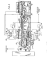
- Fig. 2 is a front view, partially in schematic form, of the doctor blade drive mechanism illustrated in Fig. 1; and
- Fig. 3 is a bottom view of a portion of the doctor blade drive mechanism shown in Fig. 2.
- Referring to Fig: 1, a web of
paper stock 20 is passed between a gravure orprinting cylinder 22 and arubber impression roller 24 pressing the web against thegravure cylinder 22. A backup or pressure roller (not shown) is sometimes mounted above theimpression roller 24 for ensuring the proper pressure between theimpression roller 24 and thegravure cylinder 22. - The
printing cylinder 22 rotates through a trough of ink (not shown) disposed below thecylinder 22. Prior to encountering the web.20, theprinting cylinder 22 passes under adoctor blade 26 which wipes the surface of theprinting cylinder 22 clean, leaving ink only in the etched wells. - In the particular doctor blade assembly as shown, the
doctor blade 26 is held against theprinting cylinder 22 by apivoting linkage 28, which includes a piston-cylinder unit for selectively moving theblade 26 away from the cylinder, for example while changing printing cylinders. - The
linkage 28 is in turn supported on a carriage ordoctor slide 12, which forms part of a drive for oscillating thedoctor blade 26 back and forth in a non-repeating motion. - The doctor blade assembly and linkage shown in Fig. 1 is an example of an assembly commercially available. The particular assembly chosen for use with the doctor blade drive of the present invention forms no part of the invention per se.
- The
doctor carriage 12 is disposed above theframe 10 and mounted on theframe 10 to be longitudinally slideable thereon. As described further below, thedoctor slide 12 is oscillated back and forth relative to theframe 10 by a hydraulic piston-cylinder unit 11 mounted between theframe 10 and the doctor slide 12. - Referring to Fig. 2, the drive components for the
doctor slide 12 are illustrated, with the pneumatic and hydraulic controls represented schematically. A first drive unit, piston-cylinder unit 11, is mounted at one end to abracket 30 which is attached to thedoctor slide 12, for example by bolts indicated at 31. At its other end, the piston-cylinder unit 11 is attached bybracket 32 to aplate 33 bolted to a portion of theframe 10. Extension and retraction of the piston of the piston-cylinder unit 11 causes back and forth movement of thedoctor'slide 12 and of thedoctor blade 26 relative to theframe 10, and therefore relative to the .printing cylinder 22. - The doctor blade drive also includes a
pneumatic valve slide 3, which provides pressure signals to a double air pilotdirectional control valve 14 for selectively supplying hydraulic fluid to the piston-cylinder 11. Thepneumatic valve slide 3 includes a first pair ofvalves valve trip brackets frame 10; are fixedly mounted on thedoctor slide 12 to move back and forth with thedoctor slide 12. As the doctor slide 12 moves back and forth, thepneumatic valve brackets pneumatic valves hydraulic control valve 14. Each pressure signal causes thevalve 14 to reverse the direction of movement of thedoctor slide 12 and thereby of thedoctor blade 26. - The
pneumatic valve slide 3 incorporates a second pair ofpneumatic valves 8 and 9. Thevalves 8 and 9 are also supplied from the source of pressurized air and provide pneumatic control signals to a second double air pilot directional control valve 5. The control valve 5 delivers hydraulic fluid to a second drive unit, in the form of a second hydraulic piston-cylinder unit 2.- The second piston-cylinder unit 2 is coupled between thepneumatic valve slide 3 and theframe 10, the latter bybolts 13, such that extension and retraction of the piston of theunit 2 causes a back and forth longitudinal movement of thepneumatic valve slide 3 on theframe 10. A second pair ofvalve trip brackets frame 10 bybolts 35 and arranged to act as end stops for thepneumatic valves 8 and 9 during back and forth movement of thepneumatic valve slide 3. Preferably, as shown in Fig. 3, thevalve trip brackets 24 25 (and similarlybrackets 18 and 19) includestops valves 8, 9 (and 16, 17) that are longitudinally spring mounted in supportingbrackets - The
doctor slide 12 is shown in its central position. In operation, thebrackets counterpart brackets brackets doctor slide 12 relative to theframe 10 and thereby relative to the fixedbrackets - Pressurized hydraulic fluid.is delivered to the hydraulic piston-
cylinder unit 2 and 11 from a common pressurized fluid source. The working pressure of the fluid delivered to the piston-cylinder unit 2 is controlled by a relief valve 4. The double air pilot directional control valve 5 (actuated, in turn, by thepneumatic valve 8 or 9) directs pressurized fluid to one of theports cylinder 2. The other port ofhydraulic clinder 2 is vented through valve 5 through one of the two pressure compensated flow control valves 6 and 7, which throttles the flow of fluid exiting from the non-pressurized side of the piston. As shown, the valves 6 and 7 have a bypass check valve portion, such that while fluid discharged fromports port - The pressure of the fluid delivered to the piston- cylinder unit 11 is controlled by a
pressure relief valve 13. One of the two ports, 22 or 23, of the piston-cylinder unit 11 is supplied with the pressured fluid as determined by the position of the double air pilotdirectional control valve 14. Thevalve 14 is actuated by the twopneumatic valves pneumatic valve slide 3 between the actuating stops 18, 19. The unpressurized port of the hydraulic cylinder 11 is vented throughvalve 14 and through a sandwichflow control valve 15, which is similar to the pressure compensated flow control valves 6 and 7 and throttles the discharge flow. The use of theflow control valves 6, 7 and 15 makes the oscillation action smooth with a minimum pause or jerk at the reversing point. - The operation of the drive control will now be described. Starting arbitrarily from one point during the cycle, the piston-cylinder unit 11 moves the
doctor slide 12 toward the left in Figs. 2 and 3. Thevalve trip bracket 19 engages thepneumatic valve 17 of theslide 3, and the actuatedvalve 17 transmits a pressure signal to pilot 21 on the double air pilotdirectional control valve 14. Pressurized hydraulic fluid is thereby delivered to theinput port 23 of the piston- cylinder unit 11, which causes the direction of movement of thedoctor slide 12. to be reversed such that it now moves toward the right in Fig. 2. Hydraulic fluid fromport 22 is . discharged through the sandwichflow control valve 15 at a throttled rate to control the rate of movement of thedoctor slide 12. - As the
doctor slide 12 continues its movement toward the right, thevalve bracket 18 engages thepneumatic valve 16. Pressurized air is delivered through thevalve 16 to thepilot 20 on the double air pilotdirectional control valve 14, reversing the flow of fluid to hydraulic cylinder 11 fromport 23 toport 22. The direction of movement of the doctor slide" 12 anddoctor blade 26 are thereby reversed. This cycle is repeated as long as air and hydraulic fluid are supplied to the system. - If the
valve slide 3 were to remain stationary, the engagement of thebrackets valves doctor slide 12 would be repeating. However, during the cycle described above, thevalve slide 3 is also caused to oscillate producing a non-repeating motion of thedoctor slide 12. Where thevalve slide 3 initially moves to the right, the double air pilot directional control valve 5 is in a position displaced toward the right in Fig. 2, such that pressurized fluid is delivered through the valve 5 toport 29. Fluid fromport 28 is vented and discharged through the valve 6 at a throttled rate to control the rate of movement ofvalve 3. - As the
valve slide 3 moves toward the right,pneumatic valve 8 contacts thevalve trip bracket 24, which actuatespilot 26 on the double air pilot directional control valve 5. Actuation of thepilot 26 reverses the flow of fluid tohydraulic cylinder 2 fromhydraulic input port 29 to thehydraulic input port 28, The piston of the piston-cylinder unit 2 is then caused to retract, reversing the direction of motion of thepneumatic valve slide 3, which then moves toward the left. - Thereafter, the pneumatic valve 9 engages the
valve trip bracket 25, which actuatespilot 27 on the double air pilot directional control valve 5, again reversing the flow of the fluid to thehydraulic cylinder 2 and the direction of notion of thepneumatic valve slide 3. This cycle is repeated as long as air and hydraulic fluid are supplied to the system. - Movement of the
pneumatic valve slide 3 relative to thestops drive 2 and by the drive 11. Movement of thedoctor slide 12 towards the right results in a corresponding component of motion of thepneumatic valve slide 3 to the left (relative to thebrackets 18 and 19) toward thevalve bracket 18. At the same time, thedrive 2 may be moving thepneumatic valve slide 3 towards the left, which accelerates the engagement ofvalve 16 andbracket 18. Alternatively, during movement to the right of thedoctor slide 12, thedrive 2 may also be moving the valve slide to the right relative to thedoctor slide 12, which retards the engagement ofvalve 16 andbracket 18. - As thus can be perceived from the foregoing description, the movement of the
doctor slide 12 back and forth is controlled by two, non-synchronous control systems. The double air pilotdirectional control valve 14, regulating the back and forth movement of thedoctor slide 12, is controlled by the back and forth movement of thepneumatic valves stops 18 , 19- The relative back and forth movement between thevalves stops piston cylinder units 2 and 11. - The rate of movement of the
doctor slide 12 and rate of movement of thepneumatic valve slide 3 are dependent upon the pressure of the hydraulic fluid which is delivered to the respectivehydraulic cylinders 11 or 2, and also by the degree of throttling from the discharge side of thecylinder 11 or 2 produced by the sandwichflow control valve 15 or the pressure compensated flow control valves 6 and 7. Thus, the rate of back and forth movement of theblade 26 may be changed by raising or lowering the hydraulic pressure. to the system or the fluid throttling characteristics. Also, the resultant oscillation stroke produced may be varied by changing the relative hydraulic pressures delivered to therespective cylinders 11 and 2, or by changing the discharge throttling characteristics of one piston-cylinder unit relative to the other. This will change the relative speeds of motion of thepneumatic valve slide 3 anddoctor slide 12. - Where the spacing between the
stops valves stops valves 8, 9 are equal, in order to establish non-repeat cycling the fluid pressure to or throttling characteristics of each cylinder is selected such that, for the relative bore size and output loads of the twocylinder units 2 and 11, the rates of movement ofpneumatic valve slide 3 relative to theframe 10 and of thedoctor slide 12 relative to the frame are not identical. The system requires no maintenance and once the desired oscillation is set no further adjustments are required. - In the doctor drive control system shown, the pneumatic control signal actuating the double air pilot
directional control valve 14 is provided as a function of the relative position of thepneumatic valve slide 3 relative to the doctor slide 12 (sincebrackets hydraulic cylinder 2 is provided as a function of the position of thepneumatic valve slide 3 relative to the frame (brackets pneumatic valves valves 8 and 9 controlhydraulic valve 14, to produce a non-repeat motion of thedoctor blade 26. In such a case, thecylinder 2 would be controlled as a function of the position of thevalve slide 3 relative to thedoctor slide 12, and the cylinder 11 would be controlled as a function of the position of thevalve slide 3 relative to theframe 10. - The foregoing represents a description of a preferred embodiment of the invention. Variations and modifications will be apparent to persons skilled in the art without departing from the inventive concepts disclosed herein. For example, the spacing between the bracket pairs 18, 19 and 24, 25 may be changed to modify the resultant non-repeat oscillation. The moveable stops do not have to be mounted on the doctor slide, only on a member that oscillates. Rather than fixing the
stops valve slide 3 moves at a set cycle, thestops cylinder units 2 and 11 to control the movement of thedoctor slide 12 . andvalve slide 3, if desired fluid can be throttled going into the cylinder ports. All such modifications and variations are intended to be within the scope of the invention as defined in the following claims.
Claims (17)
Applications Claiming Priority (2)
| Application Number | Priority Date | Filing Date | Title |
|---|---|---|---|
| US06/294,317 US4398463A (en) | 1981-08-19 | 1981-08-19 | Non-repeat doctor blade drive |
| US294317 | 1981-08-19 |
Publications (2)
| Publication Number | Publication Date |
|---|---|
| EP0072554A1 true EP0072554A1 (en) | 1983-02-23 |
| EP0072554B1 EP0072554B1 (en) | 1986-07-23 |
Family
ID=23132883
Family Applications (1)
| Application Number | Title | Priority Date | Filing Date |
|---|---|---|---|
| EP82107397A Expired EP0072554B1 (en) | 1981-08-19 | 1982-08-13 | A method of and a drive for oscillating the doctor blade in a printing press |
Country Status (6)
| Country | Link |
|---|---|
| US (1) | US4398463A (en) |
| EP (1) | EP0072554B1 (en) |
| JP (1) | JPS5842461A (en) |
| CA (1) | CA1183041A (en) |
| DE (1) | DE3272141D1 (en) |
| DK (1) | DK371182A (en) |
Cited By (3)
| Publication number | Priority date | Publication date | Assignee | Title |
|---|---|---|---|---|
| ES2068045A1 (en) * | 1990-06-07 | 1995-04-01 | Thermo Electron Web Syst Inc | Hydraulic drive for pull through doctor blade transfer system |
| DE10249512A1 (en) * | 2002-10-23 | 2004-05-19 | Donnelly Hohe Gmbh & Co. Kg | Vehicle with a device for recognizing the current traffic light signal |
| WO2008141694A1 (en) | 2007-04-27 | 2008-11-27 | Bobst Sa | Doctor blade system for a printing unit, intended for an intaglio printing machine |
Families Citing this family (9)
| Publication number | Priority date | Publication date | Assignee | Title |
|---|---|---|---|---|
| DE3220845C2 (en) * | 1982-06-03 | 1985-02-21 | M.A.N.- Roland Druckmaschinen AG, 6050 Offenbach | Drive a doctor blade device |
| IT1176525B (en) * | 1984-08-01 | 1987-08-18 | Cerutti Spa Off Mec | INSTANT REGISTRATION DEVICE FOR A RACLA GROUP, SERVED BY A CYLINDER OF A PRINTING MACHINE |
| DE3613877A1 (en) * | 1986-04-24 | 1987-10-29 | Roland Man Druckmasch | INK FOR A ROTATIONAL FLAT PRINTING MACHINE |
| IT1210291B (en) * | 1987-05-15 | 1989-09-14 | Schiavi Cesare Costruz Meccan | CYLINDER SCRAPER BLOCKING DEVICE IN A ROTOCALCO ROTARY PRINTING MACHINE |
| JP2896403B2 (en) * | 1990-01-24 | 1999-05-31 | 富士写真フイルム株式会社 | Color developing composition and processing method using the same |
| US5226363A (en) * | 1990-09-11 | 1993-07-13 | The Langston Corporation | Dual pressure preload system for maintaining a member |
| DE4401328A1 (en) * | 1994-01-18 | 1995-07-20 | Roland Man Druckmasch | Drive for an oscillating doctor device |
| ATE525209T1 (en) * | 2005-01-24 | 2011-10-15 | Gallus Ferd Rueesch Ag | ROUGH PRINTING UNIT FOR PRINTING A PRINTING MATERIAL IN A PRINTING PRESS |
| DE102007000861B4 (en) * | 2007-10-12 | 2012-03-15 | Koenig & Bauer Aktiengesellschaft | Printing units with at least two relative to each other in a horizontal direction adjustable side frame parts |
Citations (3)
| Publication number | Priority date | Publication date | Assignee | Title |
|---|---|---|---|---|
| GB588057A (en) * | 1944-01-14 | 1947-05-13 | Goss Printing Press Co Ltd | Improvements in or relating to inking mechanism for rotary intaglio printing presses |
| DE1038066B (en) * | 1955-05-09 | 1958-09-04 | Koenig & Bauer Schnellpressfab | Hydraulic drive for the squeegee in gravure printing machines |
| CH343982A (en) * | 1955-02-18 | 1960-01-15 | Hedemora Verkstaeder Ab | Device for moving doctor blades to and fro on gravure printing machines |
Family Cites Families (10)
| Publication number | Priority date | Publication date | Assignee | Title |
|---|---|---|---|---|
| US2447090A (en) * | 1944-01-14 | 1948-08-17 | Goss Printing Press Co Ltd | Rotary intaglio printing press |
| US2955460A (en) * | 1957-04-30 | 1960-10-11 | Northrop Corp | Electro-hydraulic vibration machine |
| US3009446A (en) * | 1960-03-11 | 1961-11-21 | Sunnen Joseph | Stroking device |
| US3087184A (en) * | 1960-11-17 | 1963-04-30 | Lodding Engineering Corp | Vibratory doctor mechanism |
| CH473319A (en) * | 1968-06-19 | 1969-05-31 | Hydrel Ag Maschf | Fully hydraulic device on the machine or apparatus with a straight back and forth moving part, for largely load and speed independent reversal of the accuracy of the movement of the part between two adjustable reversing points |
| DE1935253B2 (en) * | 1969-07-11 | 1972-07-13 | Maschinenfabrik Koppern & Co KG, 4320 Hattingen | HYDRAULICALLY OPERATED VIBRATION DRIVE |
| DE2015472A1 (en) * | 1970-04-01 | 1971-10-07 | Harry Kruger GmbH, 4812 Brackwede | Piston engine |
| FR2254433A1 (en) * | 1973-12-17 | 1975-07-11 | Holweg Const Mec | |
| DE2443504C3 (en) * | 1974-09-11 | 1978-11-23 | Roland Offsetmaschinenfabrik Faber & Schleicher Ag, 6050 Offenbach | Inking unit on printing machines |
| DE2731124C2 (en) * | 1977-07-09 | 1979-11-15 | Heidelberger Druckmaschinen Ag, 6900 Heidelberg | Drive for axially moving the distribution rollers of an inking unit with several rollers back and forth |
-
1981
- 1981-08-19 US US06/294,317 patent/US4398463A/en not_active Expired - Fee Related
-
1982
- 1982-05-28 CA CA000403965A patent/CA1183041A/en not_active Expired
- 1982-08-13 EP EP82107397A patent/EP0072554B1/en not_active Expired
- 1982-08-13 DE DE8282107397T patent/DE3272141D1/en not_active Expired
- 1982-08-18 DK DK371182A patent/DK371182A/en not_active Application Discontinuation
- 1982-08-19 JP JP57143974A patent/JPS5842461A/en active Pending
Patent Citations (3)
| Publication number | Priority date | Publication date | Assignee | Title |
|---|---|---|---|---|
| GB588057A (en) * | 1944-01-14 | 1947-05-13 | Goss Printing Press Co Ltd | Improvements in or relating to inking mechanism for rotary intaglio printing presses |
| CH343982A (en) * | 1955-02-18 | 1960-01-15 | Hedemora Verkstaeder Ab | Device for moving doctor blades to and fro on gravure printing machines |
| DE1038066B (en) * | 1955-05-09 | 1958-09-04 | Koenig & Bauer Schnellpressfab | Hydraulic drive for the squeegee in gravure printing machines |
Cited By (6)
| Publication number | Priority date | Publication date | Assignee | Title |
|---|---|---|---|---|
| ES2068045A1 (en) * | 1990-06-07 | 1995-04-01 | Thermo Electron Web Syst Inc | Hydraulic drive for pull through doctor blade transfer system |
| DE10249512A1 (en) * | 2002-10-23 | 2004-05-19 | Donnelly Hohe Gmbh & Co. Kg | Vehicle with a device for recognizing the current traffic light signal |
| DE10249512B4 (en) * | 2002-10-23 | 2005-04-07 | Donnelly Hohe Gmbh & Co. Kg | Vehicle with a device for detecting the current traffic light signal |
| WO2008141694A1 (en) | 2007-04-27 | 2008-11-27 | Bobst Sa | Doctor blade system for a printing unit, intended for an intaglio printing machine |
| CN101668635B (en) * | 2007-04-27 | 2012-08-08 | 鲍勃斯脱股份有限公司 | Doctor blade system for a printing unit, intended for an intaglio printing machine |
| US8915184B2 (en) | 2007-04-27 | 2014-12-23 | Bobst Mex Sa | Doctor blade system for print unit intended for a photogravure printing machine |
Also Published As
| Publication number | Publication date |
|---|---|
| JPS5842461A (en) | 1983-03-11 |
| CA1183041A (en) | 1985-02-26 |
| DK371182A (en) | 1983-02-20 |
| DE3272141D1 (en) | 1986-08-28 |
| US4398463A (en) | 1983-08-16 |
| EP0072554B1 (en) | 1986-07-23 |
Similar Documents
| Publication | Publication Date | Title |
|---|---|---|
| US4398463A (en) | Non-repeat doctor blade drive | |
| CA1062955A (en) | Pressurized ink applicator for intaglio printing press | |
| US9604446B2 (en) | Inking unit of a printing unit, printing unit and method for operating a printing unit | |
| US5167187A (en) | Throw-on/throw-off device for a blanket cylinder in the printing unit of a sheet-fed offset press | |
| GB2142908A (en) | A device useful in rotary sheet printing machines | |
| DE129494T1 (en) | DEVICE FOR CONTROLLING THE LEVEL OF PROPELLERS. | |
| GB2034655A (en) | Controlling tension in chain conveyors | |
| JPH08300616A (en) | Doctor blade for ink arrangement of rotary press | |
| GB2268480A (en) | Control for sheet grippers on a sheet-carrying cylinder. | |
| US4372203A (en) | Doctor-blade support means for silk screen printing machine | |
| US4515078A (en) | Doctor blade drive | |
| EP0286305A2 (en) | Improvements in or relating to lithographic printing | |
| US5167755A (en) | Adhesive scraper which can be adjusted in relation to an adhesive roller in a labelling machine | |
| JP5307346B2 (en) | Printer | |
| KR100326648B1 (en) | Main drive of upsetting press | |
| US3982417A (en) | Device for controlling a movable member on a machine tool | |
| SE8405368D0 (en) | WITH ROTATING MACHINERY PROVIDED PRESSURE DRIVE MACHINE DRILLING MACHINE | |
| US5135030A (en) | Electrohydraulic control system | |
| US4706565A (en) | Multi-color engraving system | |
| US3782246A (en) | Hydraulically operated vibration drives | |
| GB2331961A (en) | Device for the mutual throw-on of printing unit cylinders | |
| US3583316A (en) | Mounting of the impression cylinder of an intaglio press | |
| GB2057357A (en) | Silk screen printing machine | |
| US4510720A (en) | Honing control system | |
| US5329851A (en) | Fluidic driven self-oscillating printer roller and method |
Legal Events
| Date | Code | Title | Description |
|---|---|---|---|
| PUAI | Public reference made under article 153(3) epc to a published international application that has entered the european phase |
Free format text: ORIGINAL CODE: 0009012 |
|
| AK | Designated contracting states |
Designated state(s): BE CH DE FR GB IT LI LU NL SE |
|
| 17P | Request for examination filed |
Effective date: 19830822 |
|
| ITF | It: translation for a ep patent filed |
Owner name: BARZANO' E ZANARDO MILANO S.P.A. |
|
| GRAA | (expected) grant |
Free format text: ORIGINAL CODE: 0009210 |
|
| AK | Designated contracting states |
Kind code of ref document: B1 Designated state(s): BE CH DE FR GB IT LI LU NL SE |
|
| REF | Corresponds to: |
Ref document number: 3272141 Country of ref document: DE Date of ref document: 19860828 |
|
| PG25 | Lapsed in a contracting state [announced via postgrant information from national office to epo] |
Ref country code: LU Free format text: LAPSE BECAUSE OF NON-PAYMENT OF DUE FEES Effective date: 19860831 |
|
| ET | Fr: translation filed | ||
| PLBE | No opposition filed within time limit |
Free format text: ORIGINAL CODE: 0009261 |
|
| STAA | Information on the status of an ep patent application or granted ep patent |
Free format text: STATUS: NO OPPOSITION FILED WITHIN TIME LIMIT |
|
| 26N | No opposition filed | ||
| PGFP | Annual fee paid to national office [announced via postgrant information from national office to epo] |
Ref country code: NL Payment date: 19870831 Year of fee payment: 6 |
|
| PG25 | Lapsed in a contracting state [announced via postgrant information from national office to epo] |
Ref country code: GB Effective date: 19890813 |
|
| PG25 | Lapsed in a contracting state [announced via postgrant information from national office to epo] |
Ref country code: SE Effective date: 19890814 |
|
| PG25 | Lapsed in a contracting state [announced via postgrant information from national office to epo] |
Ref country code: LI Effective date: 19890831 Ref country code: CH Effective date: 19890831 Ref country code: BE Effective date: 19890831 |
|
| BERE | Be: lapsed |
Owner name: MOTTER PRINTING PRESS CO. Effective date: 19890831 |
|
| PG25 | Lapsed in a contracting state [announced via postgrant information from national office to epo] |
Ref country code: NL Effective date: 19900301 |
|
| GBPC | Gb: european patent ceased through non-payment of renewal fee | ||
| NLV4 | Nl: lapsed or anulled due to non-payment of the annual fee | ||
| PG25 | Lapsed in a contracting state [announced via postgrant information from national office to epo] |
Ref country code: FR Effective date: 19900427 |
|
| REG | Reference to a national code |
Ref country code: CH Ref legal event code: PL |
|
| PG25 | Lapsed in a contracting state [announced via postgrant information from national office to epo] |
Ref country code: DE Effective date: 19900501 |
|
| REG | Reference to a national code |
Ref country code: FR Ref legal event code: ST |
|
| EUG | Se: european patent has lapsed |
Ref document number: 82107397.0 Effective date: 19900418 |