EP0072432A2 - A locking device of an automotive door - Google Patents
A locking device of an automotive door Download PDFInfo
- Publication number
- EP0072432A2 EP0072432A2 EP82106272A EP82106272A EP0072432A2 EP 0072432 A2 EP0072432 A2 EP 0072432A2 EP 82106272 A EP82106272 A EP 82106272A EP 82106272 A EP82106272 A EP 82106272A EP 0072432 A2 EP0072432 A2 EP 0072432A2
- Authority
- EP
- European Patent Office
- Prior art keywords
- rod
- lever member
- key cylinder
- locking device
- door
- Prior art date
- Legal status (The legal status is an assumption and is not a legal conclusion. Google has not performed a legal analysis and makes no representation as to the accuracy of the status listed.)
- Granted
Links
Images


Classifications
-
- E—FIXED CONSTRUCTIONS
- E05—LOCKS; KEYS; WINDOW OR DOOR FITTINGS; SAFES
- E05B—LOCKS; ACCESSORIES THEREFOR; HANDCUFFS
- E05B83/00—Vehicle locks specially adapted for particular types of wing or vehicle
- E05B83/36—Locks for passenger or like doors
-
- Y—GENERAL TAGGING OF NEW TECHNOLOGICAL DEVELOPMENTS; GENERAL TAGGING OF CROSS-SECTIONAL TECHNOLOGIES SPANNING OVER SEVERAL SECTIONS OF THE IPC; TECHNICAL SUBJECTS COVERED BY FORMER USPC CROSS-REFERENCE ART COLLECTIONS [XRACs] AND DIGESTS
- Y10—TECHNICAL SUBJECTS COVERED BY FORMER USPC
- Y10S—TECHNICAL SUBJECTS COVERED BY FORMER USPC CROSS-REFERENCE ART COLLECTIONS [XRACs] AND DIGESTS
- Y10S292/00—Closure fasteners
- Y10S292/62—Lost motion connections
-
- Y—GENERAL TAGGING OF NEW TECHNOLOGICAL DEVELOPMENTS; GENERAL TAGGING OF CROSS-SECTIONAL TECHNOLOGIES SPANNING OVER SEVERAL SECTIONS OF THE IPC; TECHNICAL SUBJECTS COVERED BY FORMER USPC CROSS-REFERENCE ART COLLECTIONS [XRACs] AND DIGESTS
- Y10—TECHNICAL SUBJECTS COVERED BY FORMER USPC
- Y10T—TECHNICAL SUBJECTS COVERED BY FORMER US CLASSIFICATION
- Y10T292/00—Closure fasteners
- Y10T292/08—Bolts
- Y10T292/1043—Swinging
- Y10T292/1044—Multiple head
- Y10T292/1045—Operating means
- Y10T292/1047—Closure
-
- Y—GENERAL TAGGING OF NEW TECHNOLOGICAL DEVELOPMENTS; GENERAL TAGGING OF CROSS-SECTIONAL TECHNOLOGIES SPANNING OVER SEVERAL SECTIONS OF THE IPC; TECHNICAL SUBJECTS COVERED BY FORMER USPC CROSS-REFERENCE ART COLLECTIONS [XRACs] AND DIGESTS
- Y10—TECHNICAL SUBJECTS COVERED BY FORMER USPC
- Y10T—TECHNICAL SUBJECTS COVERED BY FORMER US CLASSIFICATION
- Y10T292/00—Closure fasteners
- Y10T292/57—Operators with knobs or handles
-
- Y—GENERAL TAGGING OF NEW TECHNOLOGICAL DEVELOPMENTS; GENERAL TAGGING OF CROSS-SECTIONAL TECHNOLOGIES SPANNING OVER SEVERAL SECTIONS OF THE IPC; TECHNICAL SUBJECTS COVERED BY FORMER USPC CROSS-REFERENCE ART COLLECTIONS [XRACs] AND DIGESTS
- Y10—TECHNICAL SUBJECTS COVERED BY FORMER USPC
- Y10T—TECHNICAL SUBJECTS COVERED BY FORMER US CLASSIFICATION
- Y10T292/00—Closure fasteners
- Y10T292/79—Bolt guards
Abstract
Description
- The present invention relates in general to an anti-thief device of an automobile, and more particularly to a locking device of an automotive door, which is operable to lock and unlock the door from outside.
- It is an object of the present invention to provide a locking device of an automotive door, of which anti-thief performance is improved.
- According to the present invention, there is provided a locking device of an automotive door, which comprises a catching device mounted in the door and including a hook member and a lever member, the hook member being locked when the lever member is moved in a first direction and unlocked when the lever member is moved in a second direction; a key cylinder rotatably mounted to the door, the key cylinder being rotatable about the axis thereof only when handled by a specified key; an arm securely connected to an end of the key cylinder and extending therefrom radially outwardly; a rod pivotally connected to the arm and extending therefrom toward the lever member, so that rotation of the key cylinder about the axis thereof induces an axial movement of the rod; and a play providing device interposed between the extending end of the rod and the lever member, so that a play is provided between the rod and the lever member upon relative movement therebetween.
- Other objects and advantages of the present invention will become clear from the following description when taken in conjunction with the accompanying drawings, in which:
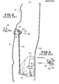
- Fig. 1 is a side view of an automobile having a sideward openable door equipped with a door locking device;
- Fig. 2 is a sectional view of a conventional door locking device, which view is taken along.a line corresponding to the line A-A of Fig. 1;
- Fig. 3 is a view taken from the direction of the arrow III of Fig. 2;
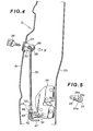
- Fig. 4 is a view similar to Fig. 2, but showing a first embodiment of the present invention;
- Fig. 5 is a view taken from the direction of the arrow V of Fig. 4;
- Figs. 6 and 7 are views respectively showing modifications of the first embodiment of Fig. 4;
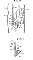
- Fig. 8 is a view similar to Fig. 2, but showing a second embodiment of the present invention;
- Fig. 9 is a view showing a modification of the second embodiment of Fig. 8; and
- Fig. 10 is a partial view showing a third embodiment of the present invention.
- Prior to describing the door locking device of the present invention, one conventional locking device will be described with reference to Figs. 1 to 3 in order to clarify the invention.
- Referring to Fig. 1, there is shown a side view of an automobile which has sideward openable hinged
doors front door 10 is shown equipped with a door looking device by which locking and unlocking of the door can be achieved by a key from outside of the vehicle. Designated bynumeral 14 is a key cylinder unit of the device, which is mounted to thedoor 10 at a position below adoor handle 16 in a manner as will be understood from the following description. - A conventional door locking device is shown by Fig. 2 and 3, particularly by Fig. 2. The device is mounted in a
door assembly 10 which includes anouter panel 18 and aninner panel 20. The device comprises acylindrical case 22 securely connected, by means of retainingclip 24, to theouter panel 18 with its enlarged flanged open end projected to the outside of thedoor 10. A key cylinder orrotor 26 is rotatably received in thecase 22 and has anarm 28 which extends radially outward. The leading end of thearm 28 is pivotally connected to an end of arod 30. The other end of therod 30 is pivotally connected to apivoting lever 32 of acatching device 34. Thecatching device 34 includes a pivotally movinghook 36 which is biased to assume the illustrated position. Thehook 36 becomes locked or unlocked in response to the pivotal movement of thelever 32 in a given direction. Although not shown in the drawing, a lock striker is mounted to a suitable portion of the vehicle body, such as a center pillar, for catching the door-mountedhook 36 upon closing of thedoor 10. - Upon requirement of locking the
door 10, thekey 38 engaged with thekey cylinder 26 is turned in a given direction, that is, for example, in a clockwise direction in Fig.1 . This movement induces an axial downward movement of therod 30 and thus a pivotal downward movement of thelever 32 thereby to lock thehook 36, thus locking thedoor 10 relative to the vehicle body. Unlocking of thedoor 10 is made by turning thekey 38 in the opposite direction. - The connecting manner between the
key cylinder 26 and thearm 28 is shown by Fig. 3. As shown, the end of thekey cylinder 26 is formed with aprojection 26a on its cylindrical end. Thearm 28 has acircular opening 28a with aconcentric recess 28b. The cylindrical end of thekey cylinder 26 is received in thecircular opening 28 with theprojection 26a located in therecess 28b. For effecting a considerable play of the key cylinder relative to thearm 28, the effective length of therecess 28b is determined greater than the thickness of theprojection 26a. The reason of providing such play is as follows: Firat, once the catching device 34 (and thus the hook 36) assumes its locked condition by the turning of thekey 38 in the given direction, the return turning of thekey 38 toward its neutral position should not induce the return movement of therod 30 which causes cancelling of the locked condition of thedevice 34. In fact, thekey 38 can not be drawn out from thekey cylinder 28 until the latter is brought into the neutral position. Second, the presence of such play induces a desirable positional relationship between theprojection 26a of thekey cylinder 26 and theconcentric recess 28a of thearm 28 when thekey cylinder 26 is brought or returned to its neutral position after achieving the door locking. At this time, theprojection 26a is in contact with or at least close to one longitudinal end of theconcentric recess 28b, which is ready for instantly unlocking thedoor 10 upon turning of thekey 38 in the opposite direction from the neutral position. - However, the above-mentioned door locking device has a weak point in an anti-thief performance. As is described hereinabove, when the
key 38 is drawn out from thekey cylinder 26 after completion of the door locking, theprojection 26a of thekey cylinder 26 is positioned close to or in contact with the longitudinal one end of therecess 28b. In this condition, thearm 28 is movable about thekey cylinder 26 until the other longitudinal end of therecess 28b is brought into contact with theprojection 26a of the key cylinder which is then locked. The direction of the movement of thearm 28 thus permitted is a direction to move therod 30 upward, that is, a direction to cancel the locked condition of thecatching device 34. This permitted movement of thearm 28 and thus therod 30 is quite undesirable when considering that they may be handled by a pick, such as a hooked wire or the like, wrongfully inserted in the door assembly from outside. In fact, simply pulling thearm 28 and/or therod 30 upwardly with such hooked wire induces the easy cancelling of the locked condition of the catchingdevice 34. - Therefore, it is an essential object of the present invention to solve the above-mentioned drawbacks encountered in the conventional door locking device.
- Referring to Figs. 4 and 5, particularly Fig. 4, there is shown a first embodiment of the present invention. In the drawings, the parts corresponding to those of the above-mentioned conventional device are designated by the same numerals. In the following, detailed description of such parts is omitted for facilitation.
- In the door locking device of the first embodiment according to the present invention, the
arm 28 is tightly connected to the end of thekey cylinder 26, unlike the above-mentioned conventional device. In particular, as is seen from Fig. 5, theprojection 26a of thekey cylinder 26 is snugly received in asmall recess 28c of thearm 28 in a manner to form a so-called spline connection therebetween. Thus, there is no play between thekey cylinder 26 and thearm 28. - In this embodiment, the play required is provided by a play providing device interposed between the
rod 30 and thepivoting lever 32 of thecatching device 34. The play providing device comprises arod holder 40 pivotally connected to thepivoting lever 32 by apivot pin 42. Theholder 40 is formed with aprojection 44 having therein a throughhole 46. Therod 30 slidably passes through thehole 46. The leadingend portion 47 of therod 30 is bent toward thecatching device 34. Two spacedstoppers rod 30 in a manner to spacedly put therein theperforated projection 44 of theholder 40. Thus, within a given range, the axial movement of therod 30 is achieved without causing the pivotal movement of thelever 32. - Upon requirement of locking the
door 10, the key 38 engaged with thekey cylinder 26 is turned in a given direction (toward this side in Fig. 4) to move therod 30 downward. This movement causes thestopper 50 to push theperforated projection 44 of theholder 40 downward to the position indicated by a solid line. With this movement of theholder 40, thelever 32 is pivoted downward thereby bringing the catching device 34 (or the hook 36) into the locked condition. Under this condition, thestopper 48 of therod 30 is apart from theperforated projection 44 of theholder 40. Then, thekey 38 is turned in the opposite direction bringing thekey cylinder 26 into the neutral position, and drawn out from thekey cylinder 26. The upward movement of therod 30 thus induced by this returningkey cylinder 26 does not affect thecatching device 34 because of the play of thestopper 48 relative to theholder 40. At this time, theholder 40 assumes the position indicated by a solid line in Fig. 4. Preferably, in this condition, thestopper 48 is in contact with or at least close to theperforated projection 44 of theholder 40 for the reason which will be described hereinnext. - Upon requirement of unlocking the
door 10, the key 38 is inserted in thekey cylinder 26 from outside and turned in the opposite direction (toward the far side of Fig. 4). With this key operation, therod 30 is lifted up, causing thestopper 48 to push theperforated projection 44 upward thus moving thelever 32 upwardly. The catchingdevice 34 thus assumes the unlocked condition. Because of the close or contact positional relationship between thestopper 48 and theprojection 44 in the neutral position of thekey cylinder 26, the counter-clockwise turning of the key 38 induces instant unlocking of the catchingdevice 34. Then, the key 38 is turned clockwise, rotating thekey cylinder 26 toward the neutral position for drawing out the key 38. The downward movement of therod 30 thus induced by the returningkey cylinder 26 does not affect the catchingdevice 34 because of the play of thestopper 48 relative to theperforated projection 44. Thus, theperforated projection 44 remains in the position indicated by a phantom line in Fig. 4, keeping the catchingdevice 34 in the unlocked condition. In this condition, thestopper 50 is in contact with or at least close to theperforated projection 44 of theholder 40, which is ready for instant locking of thedoor 10 upon the clockwise turning of the key 38 from the neutral position. - As is described hereinabove, in the locked condition of the
door 10, the parts of the locking device assume the respective positions indicated by the solid line in Fig. 4. It is to be noted that thekey cylinder 26 is kept locked until the specifiedkey 38 is operatively engaged with thekey cylinder 26. Accordingly, in the condition of Fig. 4, thearm 28 and thus therod 30 can not be moved by a tool other than the key 38. This means that the locked condition of the catchingdevice 34 can not be cancelled by a foreign tool, such as a hooked wire or the like, wrongfully inserted in the door assembly from the outside. Even though thelever 32 of the catchingdevice 34 in this condition is movable upward, that is, in a direction to cancel the locked condition of thedevice 34, thebent end portion 47 of therod 30 prevents the pick from engaging with thelever 32. - Referring to Fig. 6, there is shown a modification of the first embodiment. In this modification, a triangular prism member 47' is fixed to the lower end of the
rod 30. The two inclined sides 47'a and 47'b are effective in preventing the pick from engaging with thelever 32. In fact, such sides 47'a and 47'b are effective in guiding such tool toward the outside. - Referring to Fig. 7, there is shown another modification of the first embodiment. In this modification, the end portion of the
rod 30 is shaped like atriangular spiral 47" having aninclined side 47"a. - Referring to Fig. 8, there is shown a second embodiment of the present invention. In this embodiment, the locking device 34' is of a type, dislike that of the first embodiment, in which the locked condition of the device 34' is achieved by upward movement of the lever 32', while, the unlocked condition of the same is achieved by downward movement of the
lever 32'. The play providing device of this second embodiment comprises arod holder 40 pivotally suspended via apin 42 from the lever 32'. Therod holder 40 is formed with aperforated projection 44 through which the lower end portion of therod 30 passes slidably. Two spacedstoppers rod 30 in a manner to spacedly put therebetween theprojection 44. Atriangular member 52 having aninclined side 52a is fixed to therod 30 at a position slightly above the lever 32'. Even though the lever 32' of the catching device 32' in this condition is movable downward, that is, in a direction to cancel the locked condition of the device 34', thetriangular member 52 prevents the pick from engaging with the lever 32'. Of course, therod 30 can not be moved at this condition. - Referring to Fig. 9, there is shown a modification of the second embodiment. In this modification, a conical member 52' having a circular cone surface 52'a is employed as a substitute for the
triangular member 52 of the second embodiment. If desired, a pyramid- shaped member may be used. - Referring to Fig. 10, there is shown a third embodiment of the present invention. In this embodiment, the catching device 34' is of the same type as the second embodiment of Fig. 8. The play providing device of this third embodiment comprises an enlarged end portion 32'a of the lever 32'. The portion 32'a is formed with an elongate opening 32'b through which a bent end portion of the
rod 30 passes slidably. Thus, therod 30 has a play, relative to the lever 32', corresponding to the longitudinal length of the elongate opening 32'b. Amember 54 having an inclined side is secured to therod 30 for preventing the pick from engaging with the lever 32'. - As is understood from the foregoing description, in the present invention, the movement of the
rod 30 is not permitted by a tool other than the specifiedkey 38. Furthermore, engaging the pick with thelever 32 or 32' of the catchingdevice 34 or 34' is effectively prevented by the so-calledprotector
Claims (8)
Applications Claiming Priority (2)
| Application Number | Priority Date | Filing Date | Title |
|---|---|---|---|
| JP56130606A JPS5833679A (en) | 1981-08-19 | 1981-08-19 | Burglarproof apparatus of automobile |
| JP130606/81 | 1981-08-19 |
Publications (3)
| Publication Number | Publication Date |
|---|---|
| EP0072432A2 true EP0072432A2 (en) | 1983-02-23 |
| EP0072432A3 EP0072432A3 (en) | 1983-05-11 |
| EP0072432B1 EP0072432B1 (en) | 1986-03-26 |
Family
ID=15038228
Family Applications (1)
| Application Number | Title | Priority Date | Filing Date |
|---|---|---|---|
| EP82106272A Expired EP0072432B1 (en) | 1981-08-19 | 1982-07-13 | A locking device of an automotive door |
Country Status (4)
| Country | Link |
|---|---|
| US (1) | US4508379A (en) |
| EP (1) | EP0072432B1 (en) |
| JP (1) | JPS5833679A (en) |
| DE (1) | DE3270095D1 (en) |
Cited By (1)
| Publication number | Priority date | Publication date | Assignee | Title |
|---|---|---|---|---|
| US4867495A (en) * | 1987-07-17 | 1989-09-19 | Ohi Seisakusho Co., Ltd. | Door locking device for a vehicle |
Families Citing this family (29)
| Publication number | Priority date | Publication date | Assignee | Title |
|---|---|---|---|---|
| JPS60122468U (en) * | 1984-01-30 | 1985-08-17 | 白木金属工業株式会社 | door lock device |
| JPS6378976A (en) * | 1986-09-19 | 1988-04-09 | 株式会社 安成工業 | Door lock for car |
| US4756564A (en) * | 1986-12-19 | 1988-07-12 | Kabushikikaisha Anseikogyo | Vehicle door latch |
| US4896906A (en) * | 1987-05-27 | 1990-01-30 | The Eastern Company | Vehicle door lock system |
| US5117665A (en) * | 1987-05-27 | 1992-06-02 | Swan Jye P | Vehicle door lock system |
| US4917412A (en) * | 1987-05-27 | 1990-04-17 | The Eastern Company | Vehicle door lock system providing a plurality of spaced rotary latches |
| JPH0194569U (en) * | 1987-12-17 | 1989-06-22 | ||
| US5435609A (en) * | 1993-09-28 | 1995-07-25 | Igata; Tetzuzo | Anti-theft apparatus for vehicle door locks |
| US5511838A (en) * | 1994-02-14 | 1996-04-30 | General Motors Corporation | Remote latch release disabling device |
| US5537848A (en) * | 1994-06-27 | 1996-07-23 | General Motors Corporation | Deadbolt locking system |
| US5676002A (en) * | 1995-04-10 | 1997-10-14 | James S. Chong | Vehicle lock guard |
| GB2317917A (en) * | 1996-10-07 | 1998-04-08 | Shamim Ullah | Security enhancement for motor vehicle door locks |
| JP4158061B2 (en) | 1998-06-09 | 2008-10-01 | アイシン精機株式会社 | Vehicle door lock device |
| US5934817A (en) * | 1998-06-12 | 1999-08-10 | Chrysler Corporation | Coupling arrangement for a vehicle door lock assembly |
| US6240754B1 (en) * | 1999-06-24 | 2001-06-05 | Steven D. Petersen | Vehicle security device |
| DE10041498B4 (en) * | 2000-08-11 | 2005-10-27 | Brose Fahrzeugteile Gmbh & Co. Kg, Coburg | Locking device for a vehicle door |
| CA2444516C (en) * | 2002-10-10 | 2011-12-20 | Intier Automotive Closures Inc. | Outside release handle |
| GB2412692B (en) * | 2004-03-30 | 2006-08-09 | Mitsui Mining & Smelting Co | Door lock system |
| DE102004027381A1 (en) * | 2004-06-04 | 2005-12-29 | Kiekert Ag | Vehicle door lock has an operating lever, with an extension outside the lock housing, for direct connection to a transfer lever to accommodate the height difference between the operating unit and the lock |
| JP4504837B2 (en) * | 2005-02-28 | 2010-07-14 | 三井金属鉱業株式会社 | Door lock device |
| US20070163313A1 (en) * | 2006-01-18 | 2007-07-19 | Zamora Oscar A | Vehicle Lock |
| JP4528804B2 (en) * | 2007-06-27 | 2010-08-25 | 三井金属鉱業株式会社 | Door latch device for automobile |
| US10378237B2 (en) | 2008-12-22 | 2019-08-13 | Bauer Products, Inc. | Touch pad lock assembly with clutch system |
| US9085919B2 (en) | 2008-12-22 | 2015-07-21 | Bauer Products, Inc. | Touch pad lock assembly |
| US8393187B2 (en) | 2008-12-22 | 2013-03-12 | Bauer Products, Inc. | Remotely operated locking paddle handle latch assembly |
| US9940767B2 (en) | 2008-12-22 | 2018-04-10 | Bauer Products, Inc. | Touch pad lock assembly |
| US20100171326A1 (en) * | 2008-12-30 | 2010-07-08 | Bacon Bruce C | Lockable handle assembly |
| US8387311B2 (en) * | 2010-04-21 | 2013-03-05 | Honda Motor Co., Ltd. | Vehicle door assembly for preventing opening of the door during outer handle intrusion event |
| US8621901B2 (en) | 2010-07-20 | 2014-01-07 | Bauer Products, Inc. | Lock system for vehicles and the like |
Citations (5)
| Publication number | Priority date | Publication date | Assignee | Title |
|---|---|---|---|---|
| GB678237A (en) * | 1950-03-16 | 1952-08-27 | Vauxhall Motors Ltd | Improved door lock and latch mechanism for motor vehicles |
| FR1492020A (en) * | 1965-09-24 | 1967-08-18 | Simca Automobiles Sa | Lock control device, in particular for vehicle doors |
| US3649061A (en) * | 1970-10-16 | 1972-03-14 | Gen Motors Corp | Vehicle body door lock |
| US4113294A (en) * | 1977-06-14 | 1978-09-12 | Francis Andrew Bierman | Anti-theft clip |
| DE2815747A1 (en) * | 1978-04-12 | 1979-10-25 | Volkswagenwerk Ag | Intruder resistant motor vehicle door lock - has rear sloped plug joint face preventing break in tool engagement |
Family Cites Families (7)
| Publication number | Priority date | Publication date | Assignee | Title |
|---|---|---|---|---|
| US2782062A (en) * | 1953-01-05 | 1957-02-19 | Gen Motors Corp | Door lock |
| US3697105A (en) * | 1969-12-24 | 1972-10-10 | Atwood Vacuum Machine Co | Latch for vehicle doors |
| DE2503281C3 (en) * | 1974-02-08 | 1980-08-14 | Aisin Seiki K.K., Kariya, Aichi (Japan) | Interior locking device with an additional actuation position of the interior locking button for keyless locking of a vehicle door lock |
| JPS589226B2 (en) * | 1974-04-19 | 1983-02-19 | アイシンセイキ カブシキガイシヤ | door latch |
| JPS546227A (en) * | 1977-06-15 | 1979-01-18 | Aisin Seiki Co Ltd | Automatic door locking device |
| JPS6055672B2 (en) * | 1979-05-10 | 1985-12-06 | アイシン精機株式会社 | Automobile door lock device |
| JPS5612476A (en) * | 1979-07-09 | 1981-02-06 | Mitsui Mining & Smelting Co | Lock for automobile |
-
1981
- 1981-08-19 JP JP56130606A patent/JPS5833679A/en active Granted
-
1982
- 1982-07-13 DE DE8282106272T patent/DE3270095D1/en not_active Expired
- 1982-07-13 EP EP82106272A patent/EP0072432B1/en not_active Expired
- 1982-07-15 US US06/398,660 patent/US4508379A/en not_active Expired - Lifetime
Patent Citations (5)
| Publication number | Priority date | Publication date | Assignee | Title |
|---|---|---|---|---|
| GB678237A (en) * | 1950-03-16 | 1952-08-27 | Vauxhall Motors Ltd | Improved door lock and latch mechanism for motor vehicles |
| FR1492020A (en) * | 1965-09-24 | 1967-08-18 | Simca Automobiles Sa | Lock control device, in particular for vehicle doors |
| US3649061A (en) * | 1970-10-16 | 1972-03-14 | Gen Motors Corp | Vehicle body door lock |
| US4113294A (en) * | 1977-06-14 | 1978-09-12 | Francis Andrew Bierman | Anti-theft clip |
| DE2815747A1 (en) * | 1978-04-12 | 1979-10-25 | Volkswagenwerk Ag | Intruder resistant motor vehicle door lock - has rear sloped plug joint face preventing break in tool engagement |
Cited By (1)
| Publication number | Priority date | Publication date | Assignee | Title |
|---|---|---|---|---|
| US4867495A (en) * | 1987-07-17 | 1989-09-19 | Ohi Seisakusho Co., Ltd. | Door locking device for a vehicle |
Also Published As
| Publication number | Publication date |
|---|---|
| US4508379A (en) | 1985-04-02 |
| EP0072432A3 (en) | 1983-05-11 |
| EP0072432B1 (en) | 1986-03-26 |
| JPS641629B2 (en) | 1989-01-12 |
| DE3270095D1 (en) | 1986-04-30 |
| JPS5833679A (en) | 1983-02-26 |
Similar Documents
| Publication | Publication Date | Title |
|---|---|---|
| EP0072432B1 (en) | A locking device of an automotive door | |
| US6485071B2 (en) | Latch for vehicle closure member | |
| US6000257A (en) | Electric latch mechanism with an integral auxiliary mechanical release | |
| US4080812A (en) | Automobile trunk lock | |
| US4203621A (en) | Lock in particular for an automobile vehicle | |
| US6318770B1 (en) | Latch assembly | |
| US4783102A (en) | Latch, in particular for a motor vehicle door | |
| US6607222B2 (en) | Vehicle door latch device with one-motion door opening mechanism and antitheft mechanism | |
| US5758912A (en) | Latch member of vehicle door latch device | |
| US3930391A (en) | Lock cylinder cover with key engagement release | |
| EP0209747B1 (en) | Cylinder lock with cover | |
| US4597274A (en) | Lock cover mechanism | |
| US4586355A (en) | Lock cylinder cover with key engagement release of hold-open detent | |
| US4669764A (en) | Latching mechanism for a pivotally mounted door | |
| US3999791A (en) | Door latch device | |
| US4366683A (en) | Locking latch for a hatch door or the like | |
| US3979144A (en) | Luggage boot lid lock for motor vehicle | |
| US4730469A (en) | Lock with a lock cylinder for a floor lid of a motor vehicle | |
| US3003803A (en) | Manual safety lock for rear doors | |
| US4166646A (en) | Latching plate especially for automobile doors | |
| JP2868251B2 (en) | Door lock device for automobile | |
| JPH022846Y2 (en) | ||
| US3990734A (en) | Automatic automotive door lock | |
| AU718790B2 (en) | Outside door handle automatic locking device for automobiles | |
| JPS58763Y2 (en) | Door key opener device for automobile doors |
Legal Events
| Date | Code | Title | Description |
|---|---|---|---|
| PUAI | Public reference made under article 153(3) epc to a published international application that has entered the european phase |
Free format text: ORIGINAL CODE: 0009012 |
|
| 17P | Request for examination filed |
Effective date: 19820713 |
|
| AK | Designated contracting states |
Designated state(s): DE FR GB |
|
| PUAL | Search report despatched |
Free format text: ORIGINAL CODE: 0009013 |
|
| AK | Designated contracting states |
Designated state(s): DE FR GB |
|
| RAP1 | Party data changed (applicant data changed or rights of an application transferred) |
Owner name: NISSAN MOTOR CO., LTD. |
|
| GRAA | (expected) grant |
Free format text: ORIGINAL CODE: 0009210 |
|
| AK | Designated contracting states |
Kind code of ref document: B1 Designated state(s): DE FR GB |
|
| REF | Corresponds to: |
Ref document number: 3270095 Country of ref document: DE Date of ref document: 19860430 |
|
| ET | Fr: translation filed | ||
| PLBE | No opposition filed within time limit |
Free format text: ORIGINAL CODE: 0009261 |
|
| STAA | Information on the status of an ep patent application or granted ep patent |
Free format text: STATUS: NO OPPOSITION FILED WITHIN TIME LIMIT |
|
| 26N | No opposition filed | ||
| PGFP | Annual fee paid to national office [announced via postgrant information from national office to epo] |
Ref country code: DE Payment date: 20010709 Year of fee payment: 20 |
|
| PGFP | Annual fee paid to national office [announced via postgrant information from national office to epo] |
Ref country code: GB Payment date: 20010711 Year of fee payment: 20 |
|
| PGFP | Annual fee paid to national office [announced via postgrant information from national office to epo] |
Ref country code: FR Payment date: 20010712 Year of fee payment: 20 |
|
| REG | Reference to a national code |
Ref country code: GB Ref legal event code: IF02 |
|
| PG25 | Lapsed in a contracting state [announced via postgrant information from national office to epo] |
Ref country code: GB Free format text: LAPSE BECAUSE OF EXPIRATION OF PROTECTION Effective date: 20020712 |
|
| REG | Reference to a national code |
Ref country code: GB Ref legal event code: PE20 Effective date: 20020712 |