EP0072392A1 - Plow device - Google Patents
Plow device Download PDFInfo
- Publication number
- EP0072392A1 EP0072392A1 EP82103765A EP82103765A EP0072392A1 EP 0072392 A1 EP0072392 A1 EP 0072392A1 EP 82103765 A EP82103765 A EP 82103765A EP 82103765 A EP82103765 A EP 82103765A EP 0072392 A1 EP0072392 A1 EP 0072392A1
- Authority
- EP
- European Patent Office
- Prior art keywords
- blade
- pivot
- center blade
- center
- mounting frame
- Prior art date
- Legal status (The legal status is an assumption and is not a legal conclusion. Google has not performed a legal analysis and makes no representation as to the accuracy of the status listed.)
- Ceased
Links
Images


Classifications
-
- E—FIXED CONSTRUCTIONS
- E01—CONSTRUCTION OF ROADS, RAILWAYS, OR BRIDGES
- E01H—STREET CLEANING; CLEANING OF PERMANENT WAYS; CLEANING BEACHES; DISPERSING OR PREVENTING FOG IN GENERAL CLEANING STREET OR RAILWAY FURNITURE OR TUNNEL WALLS
- E01H5/00—Removing snow or ice from roads or like surfaces; Grading or roughening snow or ice
- E01H5/04—Apparatus propelled by animal or engine power; Apparatus propelled by hand with driven dislodging or conveying levelling elements, conveying pneumatically for the dislodged material
- E01H5/06—Apparatus propelled by animal or engine power; Apparatus propelled by hand with driven dislodging or conveying levelling elements, conveying pneumatically for the dislodged material dislodging essentially by non-driven elements, e.g. scraper blades, snow-plough blades, scoop blades
- E01H5/065—Apparatus propelled by animal or engine power; Apparatus propelled by hand with driven dislodging or conveying levelling elements, conveying pneumatically for the dislodged material dislodging essentially by non-driven elements, e.g. scraper blades, snow-plough blades, scoop blades characterised by the form of the snow-plough blade, e.g. flexible, or by snow-plough blade accessories
-
- E—FIXED CONSTRUCTIONS
- E01—CONSTRUCTION OF ROADS, RAILWAYS, OR BRIDGES
- E01H—STREET CLEANING; CLEANING OF PERMANENT WAYS; CLEANING BEACHES; DISPERSING OR PREVENTING FOG IN GENERAL CLEANING STREET OR RAILWAY FURNITURE OR TUNNEL WALLS
- E01H5/00—Removing snow or ice from roads or like surfaces; Grading or roughening snow or ice
- E01H5/04—Apparatus propelled by animal or engine power; Apparatus propelled by hand with driven dislodging or conveying levelling elements, conveying pneumatically for the dislodged material
- E01H5/06—Apparatus propelled by animal or engine power; Apparatus propelled by hand with driven dislodging or conveying levelling elements, conveying pneumatically for the dislodged material dislodging essentially by non-driven elements, e.g. scraper blades, snow-plough blades, scoop blades
-
- E—FIXED CONSTRUCTIONS
- E02—HYDRAULIC ENGINEERING; FOUNDATIONS; SOIL SHIFTING
- E02F—DREDGING; SOIL-SHIFTING
- E02F3/00—Dredgers; Soil-shifting machines
- E02F3/04—Dredgers; Soil-shifting machines mechanically-driven
- E02F3/76—Graders, bulldozers, or the like with scraper plates or ploughshare-like elements; Levelling scarifying devices
- E02F3/7609—Scraper blade mounted forwardly of the tractor on a pair of pivoting arms which are linked to the sides of the tractor, e.g. bulldozers
- E02F3/7613—Scraper blade mounted forwardly of the tractor on a pair of pivoting arms which are linked to the sides of the tractor, e.g. bulldozers with the scraper blade adjustable relative to the pivoting arms about a vertical axis, e.g. angle dozers
-
- E—FIXED CONSTRUCTIONS
- E02—HYDRAULIC ENGINEERING; FOUNDATIONS; SOIL SHIFTING
- E02F—DREDGING; SOIL-SHIFTING
- E02F3/00—Dredgers; Soil-shifting machines
- E02F3/04—Dredgers; Soil-shifting machines mechanically-driven
- E02F3/76—Graders, bulldozers, or the like with scraper plates or ploughshare-like elements; Levelling scarifying devices
- E02F3/80—Component parts
- E02F3/815—Blades; Levelling or scarifying tools
Landscapes
- Engineering & Computer Science (AREA)
- Civil Engineering (AREA)
- Structural Engineering (AREA)
- Mechanical Engineering (AREA)
- Mining & Mineral Resources (AREA)
- General Engineering & Computer Science (AREA)
- Architecture (AREA)
- Soil Working Implements (AREA)
- Electrical Discharge Machining, Electrochemical Machining, And Combined Machining (AREA)
- Control And Other Processes For Unpacking Of Materials (AREA)
Abstract
A plow device comprising variable wing plow blade (114,116) and mounting structure (10) for attaching the plow blade to a tractor, snow grooming vehicle, and the like feature distribution of the load on the blade over a relatively wide area of the supporting structural members thereby to permit reduction in their size, weight and number and in their manufacturing and assembling costs while maintaining the essential structural strength, and are further characterized in the attainment of improved performance and utility in respect of independence of the plow blade height and pitch or roll, tilt and wing blade adjustments, and greater freedom of movement of the wing blades of the plow blade both forwardly and rearwardly, from a position of alignment with the center section of the plow blade.
Description
- This invention is a divisional case from European patent application no. 79101826.0, where the plow device is claimed in connection with first and second frame means as well as first to third connecting means.
- The invention relates to an improved plow device, especially a material handling or treating plow blade and mounting structure therefore that are attachable to a tractor, snow . grooming vehicle, and similar self-propelled vehicles. The plow blade may be a scraper blade, a snow plow blade, or other plow blade for which, in operation, there is required adjustability in the height of the blade above the terrain, and adjustability, also, in the cutting angle or angle of attack of the blade in three dimensions, that is along three separate pivotal axes each of which is spaced 90° from the others.
- Different forms of mounting structures for material handling or treating plow blades have been Droposed in the prior art for providing height and three dimensional blade adjustability. One form disclosed in U. S. Patent 3,157,099, granted November 17, 1964, utilizes a C-frame pivotally mounted on a tractor and a two-section plow blade, a three-section plow blade being suggested but neither illustrated nor otherwise described, attached at a vertically hinged connection of the blade sections by a pivot pin or pintle to the C-frame, the pintle extending centrally and.longitudinally of the tractor. The main thrust of the load on the plow blade is concentrated on the pintle connection to the.C-frame. Therefore, in order to provide the essential strength the C-frame necessarily must be massive and heavy. As a result, the mounting structure is costly to manufacture and difficult to assemble. Moreover; special hydraulically actuated rams are needed to support and adjust the ends of the plow blade sections, further adding undesirably to the difficulty and cost of manufacture and assembly.
- Another form of mounting structure for a material treating plow blade is disclosed in U. S. Patent 3,822,751, granted July 9, 1974. The structure there shown provides, for a single section plow blade, adjustability in height and culling angle in three planes, and comprises an assembly of five different frames that are pivotally connected to each other, the connection of the second and third frames to each other being by a single centrally located vertically disposed pivot carried at the vertex of a triangular portion of the second frame. The first frame is attached to a tractor and the fifth frame to the plow blade. Here, too, the main thrust of the load on the plow blade is concentrated on a single pivot, the vertically-disposed pivot connection between the second and third frames. This requires those frame, particularly, to be massive and heavy, adding further to the difficulty and cost of manufacture and assembly of a complex assortment of frames.
- While the mounting structures of patents 3,157,099 and 3,822,751 both provide for height and three dimensional adjustability of the plow blade, the structures are such that adjustment of the blade height, in each case, undesirably alters the pitch or roll angle of the blade. Accordingly, a compensating pitch angle adjustment is required whenever the height of the blade is changed if the optinum pitch angle for the resistance characteristics of the material being handled or treated is to be maintained.
- Three-section forms of plow blades for attachment to a tractor are disclosed in U. S. Patents 3,477,151, granted November 11, 1969 and 4,019,268, granted April 26, 1977. Specifically, patent 3,477,151 shows a snow plow comprising a center or primary blade and two wings or flanking auxiliary blades, each pivotally connected about an upright or vertical axis at an associated end of the center blade, the manner of attachment of the snowplow to a self-propelled vehicle not being shown. The wing blades are connected for simultaneous limited inverse pivotal movement with respect to the center blade, from relative positions wherein one wing blade is aligned with the center blade when the other is at an angle rearward of less than 180° therewith. Forward pivotal movement of the wing blades with respect to the center blade is not permitted.
- Patent 4,019,268 shows a three-section plow blade for snow compacting equipment in which the blade is pivotally secured to a vehicle by first and second frames parallel to the blade and by a pair of third frames that extend normal to the second frame. The three-section blade includes a center blade-and two wing blades, each pivotally connected to an associated end of the center blade. The pivotal connections are horizontal whereby the wing blades, when actuated relatively to the center blade, pivot upwardly.. This facilitates transportation of the equipment to and from ski trails and for storage when not in use. The structure does not provide for either downward, rearward or forward pivotal movement of the wing blades with respect to the center blade.
- Accordingly, there still exists a need for improvements in the mounting structures or assemblies for plow blades, particularly in respect to an arrangement for a plow blade having variably adjustable wings: (a) that simplifies the construction and reduces the size and weight of the components while maintaining the essential structural strength, reduces the number of component parts and their manufacturing and assembly cost; (b) wherein the height adjustment of the plow blade is substantially independent of the cutting angle adjustments thereof,-and in particular, the pitch or roll angle adjustment; and (c) wherein the adjustable wings 3f the plow blade have greater freedom of movement independently of each other, including forward as well as rearward pivotal movement with respect to the center blade.
- Among the objects of the invention is the provision of a variable wing plow blade and mounting structure therefor for attachment to tractors and similar self-propelled vehicles that avoids the problems and limitations of the prior art plow blades and mounting structures.
- Another object of the invention is to provide such a variable wing plow blade and mounting structure therefor that is less expensive to manufacture and to assemble.
- Another object of the invention is to provide an improved and simplified mounting structure for a variable wing plow blade wherein the load on the blade is distributed ovcr a substantial area of the supporting components of the mounting structure whereby the size and weight of the components may be reduced while maintaining rigidity and structural strength, and wherein more strength is provided where the structure.mounts to the vehicle chassis.
- A further object of the invention is to provide such an improved mounting structure for a variable wing plow blade that provides a plurality of independent adjustments of the blade in three dimensions, including a height adjustment of the blade that is substantially independent of and does not adversely affect any of the other adjustments.
- Still another object of the invention is to provide such an improved mounting structure for a variable wing plow blade that provides freedom of movement of the wing blades, selectively and independently of each other, both forwardly and rearwardly of the center, blade.
- Another object of the invention is to provide such an improved mounting structure for a variable wing plow blade that includes a plurality of control means, and particularly, hydraulic motor means, thereby to enable the vehicle operator to make the various plow blade adjustments from a readily accessible control panel in the cab.
- Yet another object of the invention is to provide such an improved mounting structure for a variable wing plow blade wherein the hydraulic motor means includes relief valve means to prevent damage to the plow blade in the event either wing hits an immovable object.
- In accomplishing these and other objectives of the invention, there is provided a mounting structure or assembly for attaching a plow blade having a center blade and variably adjustable wing blades to a vehicle such as a tractor, snow grooming vehicle, or the'like. The mounting structure includes a first horizontally positioned-rectangular mount- frame that is pivotally attached at one end by a pivot mount to the vehicle. The mount frame extends forwardly of the vehicle from a position adjacent the front axle thereof.
- The mounting structure further includes a second horizontally positioned rectangular push frame that is rigidly attached at the rearward end thereof to the forward end of the first frame. For convenience hereinafter the first and second frames are designated first frame means. The forward end of the first frame means is pivotally attached by first connecting means to a second frame means, a generally vertically positioned rectangular mounting frame, at a position adjacent the lower edge of the latter. The second frame means includes a pair of spaced vertically extending members and a lower horizontal cross member on which three spaced vertical posts are mounted. The cross member and posts are positioned in a plane that is forward of the general vertical plane of the second frame means. The center blade of the plow is attached to the cross member by means designated second connecting means and to the posts by third connecting means. The cross - member and posts provide support for the center blade of the plow over a substantial portion of the rear surface thereof, the third connecting means restraining movement therebetween except for limited relative tilting of the center blade about a pivotal axis provided by said second connecting-means.
- The mounting structure according to the invention further includes control means, specifically hydraulic motor means, so connected between the vehicle and the several frame means and between certain members of the frame means as to effect various adjustments of the plow blade in each of three dimensions, that is, along three separate pivotal axes that are spaced 90° apart, for convenience designated coordinate X, Y and Z axes.. Each such adjustment is independent of the others including an adjustment of the height of the plow blade with respect to the vehicle and the terrain. One such pair of hydraulic cylinders is connected between the vehicle and the second frame means. These hydraulic cylinders, when actuated, raise or lower the forward end of the second frame means and'thereby adjust the height of the plow blade about a horizontal transverse axis provided by the pivot mounts at the rear of the first frame means. The effective lever arm involved in making this adjustment is the combined length of the first and second frame means.
- Another pair of hydraulic cylinders connected between the vehicle and the vertically extending members of the second frame means, when actuated, tip the second frame means and thereby the plow blade, backward or forward. This provides a pitch or roll adjustment of the plow blade. The pivotal axis of this adjustment is a.horizontal transverse axis, for example, a Z-Z axis, located at the forward end of the first frame means. The invention features the use of extension arms in association with this pair of hydraulic cylinders of such length and so positioned that each extension arm and the lever arm for raising or lowering the plow blade effectively comprise opposite arms of a parallelogram. Consequently, as those skilled in the art will understand, adjustment of the height of the plow blade is substantially independent of and does not adversely affect the pitch or roll adjustment of the plow blade.
- A hydraulic cylinder connected between a sideward extending pivot arm or tongue on the second frame means and the plow blade center section, when actuated, tilts the . center blade of the plow relatively to the second frame means about the axis of the pivot connection of these components, for example, a Y-Y axis, thereby to raise or lower the ends of the plow blade.
- A pair of hydraulic cylinders connected between rearwardly extending pivot arms or tongues on the plow center blade and on each of the wing blades, when actuated, horizontally adjust the cutting angle of the wing blades with respect to the center blade, such adjustment of the wing blades being about a generally vertical hinge pivot connection of each wing blade to a respective end of the center blade, and being either forward or rearward with respect to the center blade. Each such adjustment is about an X-X axis and is selectively independent of the other.
- The various hydraulic cylinders are actuatable from a readily accessible control panel provided in the cab of the vehicle. Additionally,.relief valve means are provided in accordance with the invention to release the pressure in the hydraulic cylinders to prevent damage to the plow blade in the event either adjustable wing hits an immovable object thereby to prevent damage to the plow blade.
- A better understanding of the invention may be.had from the following detailed description when read in connection with the accompanying drawings wherein:
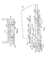
- Figure 1 is a side elevation of the mounting structure or assembly of the variable wing plow blade of the present invention, taken along the line 1-1 of Figure 2 with a forward portion of a tractor added in dot-dash lines;
- Figure 2 is a top plan view of the mounting assembly and plow blade structural arrangement of Figure 1 showing certain portions in cross section;
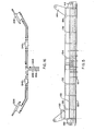
- Figure 3 is an exploded perspective view of the mounting assembly frame and plow blade arrangement of Figures 1 and 2, with the variable wing blade sections omitted;
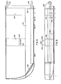
- Figure 4 is a rear elevation of the second frame means of the mounting assembly;.
- Figure 5 is a bottom plan view of the center blade section of the variable wing plow blade;
- Figure 6 is a diagrammatic rear view of the plow blade center section;
- Figure 7 is a diagrammatic end view of the plow blade center section as seen from the left in Figure 6;
- Figure 8 is a diagrammatic bottom plan view of the right-hand wing blade section of the variable wing plow blade of Figure 2;
- Figure 9 .is a diagrammatic rear view of the right-hand wing blade section of the variable wing plow blade of Figure 2;
- Figure 10 is a diagrammatic end view of the right-hand wing blade section, as seen from the right in Figure 8;
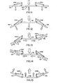
- Figures 11 through 15 are schematic representations of the variable wing plow blade of the present invention, the several views illustrating typical controlled positions to which the wing blade sections may be moved with respect to the center blade section; and
- Figure 16 is a partial schematic piping diagram, including relief valve means, for controlling hydraulic motor means provided for actuating the wing blades of the variable wing plow blade.
- Referring to Figures 1 to 3 of.the drawings, the mounting structure or assembly, indicated generally by
reference numeral 10, comprises aframe 12, aframe 14, and a second frame means 16. Theframes frame 16, designated a second frame means or mounting frame, are all rectangular in configuration and are formed of generally square tubular members. The first frame means 12, 14 are supported, in a manner to be described, in generally horizontal positions, the second frame means 16 being pivotally connected by first connecting means in a generally vertical position to the forward end of the first frame means 12, 14. - The
first frame 12, includes sideby'side frame members assembly 10 is to be attached, by a cross ortransverse member 22. Outboard of and connected to theside frame members cross member 22 are additional wedge shapedside frame members cross member 22. Pivotbearings side frame members cross member 22, for the pivotal attachment of-the end offrame 12 to the vehicle chassis, indicated by dot-dash lines 32 in Figure 1, by means of pivot mounts 34 and 36. Both ends of-the pivot mounts 34 and 36 are bolted to thechassis 32, as by cap screws 38. - The forward end of each
pivot mount bearinq pivot pin side frame members assembly 10, as will become apparent, about the axis of the pivot pins 43 and 44, an axis that is substantially heri- zontal and perpendicular to a longitudinal center line of thevehicle chassis 32. - The
frame 14 includes side byside frame members a-cross member 50 and at the other end by across member 52, and that are additionally connected bydiagonal members side frame members cross member 52, are pivot mounts 58 and 60. These pivet mounts are provided for the pivotal attachment of theframe 14 to the second frame means 16. Pivot mounts 58 and 60 each includes a forwardly extending fork shaped portion in which two vertically spacedbearings clevis 70, 72 that is provided at the rear of the second ; frame means 16, as seen in Figure 4, by arespective pivot pin bearings respective bearing - The second frame means 16, as seen particularly in Figures 3 and 4, includes a pair of vertically spaced generally
horizontal cross members angle end members upstanding posts horizontal members upstanding end members Members members member 86 being presented to one side offrame 16 and an edge ofmember 88 to the other-side of the frame. Thus,cross member 84 extends between a pair pf facing sides of members 86'and 88 and the other sides of members 86-and 88-face the rear side ofcross member 82, each such side being adjacent an associated end ofmember 82. - Each of the spaced posts 90, 92 and 94 is positioned on the upper surface of
cross member 82, being ridigly connected thereto, and extends vertically for a distance such that the rear top edge of each post is adjacent the lower forward edge ofcross member 84, being connected together, as by welding. Theposts pivot 102 provided at the center of and extending through thecross member 82 substantially parallel to a longitudinal center line-of thevehicle chassis 32. - As seen in Figure 3, particularly,
pivot bearings arms tongue 108 is provided at the right end ofcross member 82, the pivot arm in effect comprising an extension ofmember 82.. Thepivot bearings pivot arm 108 comprise motor means connections for providing pitch angle and tilt angle adjustments of the variable wing plow blade in a manner to be described. - The variable wing plow blade, indicated generally by
reference numeral 110, includes an elongated center blade orsection 112, a right wing blade orsection 114 and a left wing blade orsection 116. Thewing blades section 112, in a manner to be described, for angular movement in a horizontal plane in both directions from a position of alignment withthe'center blade 112. - The plow
blade center section 112, as illustrated in detail in Figures 5, 6 and 7, is comprised of ablade 118 having at its lower front or material engaging edge an elongated protective angle iron or wearbar 120 which may include asnow blade tooth 121, as indicated. Theblade 118 is supported at the lower rear side thereof by a generally rectangularelongated tube 122 the ends of which are closed byplates tube 122, at the left and right ends, respectively, as seen in Figure 6, are upstandingU-shaped frame members tube 122 additionally supports on its upper surface, intermediate the ends thereof, three upstanding spacedU-shaped members upstanding posts push frame 16. - The plow
blade center section 112 further includes on its rear side, at the left and right ends thereof, as seen in Figure 6, upper and lower sets of spacedrectangular hinge pads tongues hinge pads upstanding member hinge pads tube end plate center section 112, to the rear side of an associatedU-shaped member - At the upper end of the
U-shaped member 128, as seen particularly in Figures 5 and 6, there is provided an additionalU-shaped member 150 that extends to the rear frommember 128 and includes, centrally thereof, abearing 152. - The upstanding
U-shaped members curved slot slots posts push frame 16. Additionally, therectangular tube 122 is provided with a bearing.160 at a center portion thereof that is in alignment.with the bearing 102 in the-horizontal member 82 of the push frame when theplow center blade 118 positioned for proper support with respect to thepush frame 16. With thecenter blade 112 so positioned, the rear surface oftube 122 abutscross member 82, the rear surfaces of theU-shaped members posts slots slots - As shown in Figure 3, the plow blade center section l12 is pinned or bolted to the
push frame 16 by a hex head cap screw 162 and uni-torque nut 164, a flat washer being provided, as suitable, these members, for convenience, being designated second connecting means. The plow blade center-section 112 is also held to thepush frame 16 by third connecting means, specifically hex head cap screws 166, 168 and 170 that extend, respectively, through the associated pairs ofslots uni-torque nuts - In accordance with the invention the several cap screws and nuts holding the plow
blade center section 112 to thepush frame 16 are tightened sufficiently to hold these members snugly together thereby providing firm support for the plow blade l18 over a substantial portion of the rear surface of thecenter section 112, but allowing limited relative pivotal movement of thecenter section 112 with respect to thepush frame 16 about the pivot ofbearings - The plow
blade wing sections Fiqures 8, 9 and 10 theright wing section 114 only. Thewing section 114, as shown particularly in Figure 10, includes ablade 178, the curvature of which corresponds to that ofcenter blade 118. At the lower front edge the blade-178 is provided with an elongated angle iron or-wear bar 180 including asnow blade tooth 181.Blade 178 is supported at the lower rear side by a generally rectangularelongated tube 182 the ends of which are closed byplates 184 and 18G. Provided on and supported by the upper surface oftube 182, as seen in Figures 8 and 9, are two upstandingU-shaped frame members upper pivot arm 192 is attached to the inboard side ofU-shaped member 190 and alower pivot arm 194 is attached to theadjacent closure plate 184. Pivotarms respective bearing pivot arm 200 having a bearing 201 is provided onU-shaped member 188. - It will be understood that the several structural members or components of which the
center blade section 112 and the wing blade sections l14 and 116 are formed may be a.ttached to each other in any suitable manner as by welding, for example, to the end that each section in practice, is made to comprise a unitary rigid structure. When formed of materials conventional for the purpose thecenter blade 112 and the wing blades l14 and 116 may be made to embody the necessary and desired strength required for material treating or handling plows. - The
wing blade section 114 is hinged to the right end ofcenter blade section 112, as seen in Figure 2, by placing theupper pivot arm 192 between theupper hinge pads 142 of the center blade section, placing thelower pivot arm 194 between thehinge pads 144, and as indicated in Figure 6, inserting ahinge pin - As seen in Figure 2, a
hydraulic motor 206, comprising a cylinder and ram, has one end connected to thepivoL arm 200 of the--wing blade section 114 and the other end connected to thepivot arm 148 of thecenter blade section 112.Hydraulic motor 206 is operative when actuated to move the wing blade section l14 with respect to the center blade section l12 in a generally horizontal plane about the vertical pivotal axis provided by the hinge pins 202 and 204 from a position in which the center and wing blade sections are in alignment, as illustrated in Figure 1, to positions in which thewing blade section 114 is moved forwardly of thecenter blade section 112, as shown in Figure 13, and in which thewing blade section 114 is moved rearwardly of thecenter blade section 112, as shown in Figure 15. Ahydraulic motor 208 which may be identical to themotor 206 is connected in a similar manner between theleft wing section 116 and thecenter blade section 112 for effecting forward and rearward movements of thewing blade section 114, as seen in Figure 2, with respect tocenter blade section 112, from a position of alignment therewith. - Figures 11-15 illustrate typical ones of a wide range of positions to which each of the wing blades or sections l14 and 116 can be adjusted in a generally horizontal plane with respect to the
center blade section 112, from a rear angle position to a forward angle position. Thus, with bothwing blades center blade 112, the variablewing plow blade 110 is operative as a straight plow blade, as shown in Figure 11. With both wing blades l14 and 116 angled forward in the direction of movement of the vehicle, as shown in Figure 12, the variablewing plow blade 110 is operative as a conventional U-blade for pushing forward the material being handled. Withwing blade 114 angled forward andwing blade 116 angled backward, as shown in Figure 13, the variablewing plow blade 110. is operative to move the material being handled to one side of the vehicle. In this condition of adjustment, snow, for example, can be transferred from the edges to the centers of narrow trails. In order to transfer the material to be handled to the opposite side of the vehicle, the wing blades l14 and 116 may be adjusted to the positions illustrated in Figure 14. With thewing blades - In accordance with the invention the
hydraulic motors wing plow blade 110. Specifically, for varying the tilt angle, there is provided, as shown in Figure 1, ahydraulic motor 210 having a cylinder and ram with one end connected by a clevis to thepivot arm 108 on the end of thepush frame 16 and the other end connected by a clevis to thebearing 152 on theU-shaped frame 150 of thecenter blade section 112. - For varying the height of the variable
wing plow blade 110 off the ground, there is provided twohydraulic motors Motor 214, as seen in Figures 1 and 3, has one end connected by a clevis to bearing 80 in pivot mount 60 ofmount frame 14 and the other end connected by a clevis to a mountingplate 216 that is bolted in any suitable manner to the side ofvehicle chassis 32.Motor 212, as best seen in Figure 2, has one end connected to thebearing 78 in pivot mount 58 ofmount frame 14 and the other end connected by a clevis to a mountingplate 218 that is bolted in any suitable manner to the side of thevehicle chassis 32 opposite that to which mountingplate 216 is attached. Upon actuation,motors lower frames arms - In order to vary the pitch angle of the plow blade there is provided a pair of
hydraulic motors extension arms motor 222, as seen in Figures 1 and 2, is connected to the bearing at the upper end ofupstanding member 88 of the second frame means or pushframe 16 and the other end is connected by a pin indicated at 228 in the adjacent end. of theextension arm 224. The other end ofextension arm 226 is attached by a mountingpin 230 to ananchor pad 232 that is bolted to the side of thevehicle chassis 32, above the hydraulicmotor mounting plate 216 and further to the rear of the vehicle. - Similarly, one end of
hydraulic motor 220, as seen in Figure 2, is connected by a clevis to thebearing 104 at the upper end ofupstanding member 86 of the push frame.16, the other end ofmotor 220 being connected.by apin 234 to theextension arm 226 near one end thereof. - The other end ofextension arm 226 is attached by a mountingpin 236 to ananchor pad 238 that is bolted on the other side of thevehicle chassis 32, at a position substantially directly opposite the position at whichanchor pad 232 is bolted to thechassis 32. - Actuation of
hydraulic motors push frame 16 and thereby the variablewing plow blade 110 are tipped forwardly or backwardly about the axis of thepivot bearings arms frames - In general the fluid supply means, the hydraulic piping or circuitry, and the control panel means-for selectively actuating the several hydraulic motor means form no part of the present invention and have not been illustrated in order. to avoid undue complication of the drawing. The invention features, however, the use of relief valve means in connection with the
hydraulic motors wing blades center blade 112, thereby avoiding damage to the wing blade and also to the center blade. - Specifically, there are provided relief or cushion
valves 240 and 242 in the hydraulicfluid line connections hydraulic motors Relief valves 240 and 242 may be of known type, and for example, may each comprise a Vickers relief valve, a balanced piston type relief valve with piston of equal areas on both sides and which provides for the escape of hydraulic fluid directly to the tank in the event of excessive fluid pressure in the lines tomotors fluid line 244 is a common line connected through both ofrelief valves 240 and 242 to one fluid input of both of thehydraulic motors Line 246 is connected throughrelief valve 240 to the other fluid input ofmotor 206. Similarly,line 248 is connected through relief valve 242 to the other fluid input ofmotor 208. It is believed that the operation of the relief valves in releasing pressure in the associated motor in the event that eitherwing blade 114 and l16 hits an immovable object will be apparent to those skilled in the art. - Thus, there has been provided in accordance with the invention a novel variable wing plow blade and a novel mounting structure or assembly therefor that avoids the problems and limitations of the prior art blades and mounting structures or assemblies. The novel mountinq assembly provides the essential structural strength required while permitting a reduction in the size, weight and number of components required, thus achieving a desired reduction in cost of manufacturing and assembly. The assembly further provides improved performance in respect of rendering substantially independent of each other the height and pitch angle adjustments of the plow blade. Additionally, the assembly and novel plow blade provide greater freedom of movement of the plow blade with respect to the assembly than is possible with the prior art constructions, including movement, both independently of each other and with respect to the center blade, of the wing blades, rearwardly as well as forwardly of the center blade. Motor means comprising double acting hydraulic cylinders or jacks enable the various plow blade adjustments to be made from a control panel in the cab, relief valve means being provided for avoiding damage in the event either wing blade hits an immovable object while the vehicle is in motion.
Claims (10)
1. Plow device which can be attached to a vehicle, comprising an elongated center blade (112) and first and second wing blades (114, 116), each of said center and wing blades (112, 114, 116) having working surfaces adapted to contact a substance to be plowed, said wing blades each being generally vertically pivotally connected at cne end to a respectively associated end of said center blade (112) for angular adjustment in position with respect to said center blade and each including a separate first pivot arm {200) extending rearwardly from an intermediate position thereof, and providing a generally vertical pivot connection, characterized in that said center blade (112) including a separate rearwardly extending second pivot arm (146, 148) adjacent each end thereof, said second pivot arm providing a generally vertical pivot connection, and first and second motor means (206, 208), connected respectively, between an associated one of the vertical pivotal connections of said second pivot arms (146, 148) and an associated one of the vertical pivotal connections of said first pivot arms (200), and that each of said first and second motor means (206, 208) is operative independently of the other whereby each of said first and second wing blades (114, 116) is forward and rearward angularly adjustable in position with respect to said center blade (112) independently of the other.
2. Plow device as specified in claim 1, characterized in that each of said motor means includes a hydraulic cylinder and ram (206, 208).
3. Plow device as specified in claim or 2, characterized by a generally vertically positioned mounting frame (16) having mounting means (96-100, 160-176) for mounting said center blade (112) on said frame (16) in position generally parallel thereto.
4. Plow device as specified in claim 1, characterized in that said center blade (112) is mounted to the mounting frame (16), which includes a generally horizontal pivot means (102) that extends along an axis transversely of said center blade (112) and mounting frame (16) whereby to provide for relative angular adjustment of said center blade and mounting frame (16).
5. Plow device as specified in one of the claims 1 to 4, characterized in that said transverse pivot means (102) is generally centrally located with respect to said center blade (112) and said mounting frame (16) includes a first pivot arm (108)extending parallel thereto, said center blade (112) includes a third pivot arm (150) that extends rearwardly thereof, said mounting frame first pivot arm (108) and center blade third pivot arm (150) being spaced generally vertically from each other and each providing a generally horizontal pivot connection transverse to said center blade (112) and mounting frame (16), and third motor means (210) connected between said mounting frame first pivot arm (108) and said center blade third pivot arm (150) for controlling the relative angular adjustment of said center blade (112) with respect to said mounting frame (16).
6. Plow device as specified in claim 5, characterized in that said third motor means (210) includes a hydraulic cylinder and ram.
7. Plow device as specified in one of the claims 1 to 4, characterized in that said transverse pivot means (102) comprises a pivot pin (162) that pivotally connects said center blade (112) and mounting frame (-16)at a position substantially in horizontal alignment with said mounting frame first pivot arm (108), wherein said mounting means includes at least one curved slot (96-100) the curvature of which corresponds to that of the arc of the circle having said pivot pin (162) at its center, and wherein said center blade (112) is further connected to said mounting frame (16) by at least one pin connection (166-170) of said center blade to said curved slot (96-100).
8. Plow device as specified in oneof the claims 1 to 7, characterized in that said mounting means includes a plurality of curved slots (96-100) the curvatures of each of which correspond to that of the arc of a circle having said pivot pin (162) at its center, and wherein said center blade (112) is connected to said mounting frame (16) by additional pin connections (166-170) of said center blade (112) and said curved slots (96-100).
9. Plow device as specified in one of the claims 1 to 8, characterized in that said mounting frame (16) and said center blade 4112) each include at least one curved slot (96-100; 154-158) facing each other, the curvature of each of said slots corresponding to that of the arc of the circle having said pivot means.(102) at its center, and wherein said center blade (112) is further connected to said mounting frame (16) by pin connection (166-170) if said facing curved slot.
10. Plow device as specified in one of the claims 1 to 9, characterized by pivot mount means (34-44) having a forward end and a rearward end, said rearward end (34, 36) being adapted to a tractor (32) and by horizontal frame means (12,14) which include pivot means (28,30) at the rearward end thereof that connect the rearward end of said frame means (12, 14) to the forward end of said pivot mount means (34-44).
Applications Claiming Priority (2)
| Application Number | Priority Date | Filing Date | Title |
|---|---|---|---|
| US05/916,613 US4249323A (en) | 1978-06-19 | 1978-06-19 | Variable wing plow blade and mounting structure therefor |
| US916613 | 1978-06-19 |
Related Parent Applications (1)
| Application Number | Title | Priority Date | Filing Date |
|---|---|---|---|
| EP79101826.0 Division | 1979-06-08 |
Publications (1)
| Publication Number | Publication Date |
|---|---|
| EP0072392A1 true EP0072392A1 (en) | 1983-02-23 |
Family
ID=25437566
Family Applications (2)
| Application Number | Title | Priority Date | Filing Date |
|---|---|---|---|
| EP82103765A Ceased EP0072392A1 (en) | 1978-06-19 | 1979-06-08 | Plow device |
| EP79101826A Expired EP0007000B1 (en) | 1978-06-19 | 1979-06-08 | Plow device |
Family Applications After (1)
| Application Number | Title | Priority Date | Filing Date |
|---|---|---|---|
| EP79101826A Expired EP0007000B1 (en) | 1978-06-19 | 1979-06-08 | Plow device |
Country Status (5)
| Country | Link |
|---|---|
| US (1) | US4249323A (en) |
| EP (2) | EP0072392A1 (en) |
| AT (1) | ATE5983T1 (en) |
| CA (1) | CA1115952A (en) |
| DE (1) | DE2966573D1 (en) |
Cited By (3)
| Publication number | Priority date | Publication date | Assignee | Title |
|---|---|---|---|---|
| EP0124922A1 (en) * | 1983-04-01 | 1984-11-14 | LEITNER S.p.A. | Hydraulically-controlled bulldozer blade-attachment |
| GB2183271A (en) * | 1985-11-26 | 1987-06-03 | Multimate Limited | Scraper/collector means attachable to a tractor |
| EP0592262A1 (en) * | 1992-10-08 | 1994-04-13 | Giandomenico Pelazza | Blade/device for cleaning roads and the like |
Families Citing this family (71)
| Publication number | Priority date | Publication date | Assignee | Title |
|---|---|---|---|---|
| US4249323A (en) * | 1978-06-19 | 1981-02-10 | De Lorean Manufacturing Company | Variable wing plow blade and mounting structure therefor |
| US4306362A (en) * | 1980-05-12 | 1981-12-22 | Valley Engineering, Inc. | Blade assembly |
| CA1195163A (en) * | 1981-11-18 | 1985-10-15 | Howard W. Long | Method and apparatus for removing ice from paved surfaces |
| US4821436A (en) * | 1983-11-14 | 1989-04-18 | Slocum Alexander H | Blow system |
| NO153864C (en) * | 1984-01-19 | 1986-06-11 | Stiansen & Oeya A S | DEVICE FOR FRONT MOUNTED SNOW CARD PLOGRAMS. |
| IL78706A (en) * | 1986-05-06 | 1990-09-17 | Israel Defence | Automotive earth moving vehicle |
| US5205058A (en) * | 1990-04-25 | 1993-04-27 | Allen A Gregory | Roadbed maintenance device |
| US5036607A (en) * | 1990-07-10 | 1991-08-06 | Taylor Carlos V | Combination lift, shovel and bucket attachment for vehicles |
| DE4211039C2 (en) * | 1992-04-03 | 1998-07-02 | Weimar Werk Baumaschinen Gmbh | Support plate for excavators or mobile machines |
| US5285588A (en) * | 1992-07-13 | 1994-02-15 | W. Wally Niemela | Winged plow |
| DE4229459A1 (en) * | 1992-09-03 | 1994-03-10 | Macmoter Spa | Construction vehicle |
| US5389958A (en) * | 1992-11-25 | 1995-02-14 | Tektronix, Inc. | Imaging process |
| US5265355A (en) * | 1992-12-15 | 1993-11-30 | Daniels Pull Plow, Inc. | Rear-mounted snow plow apparatus |
| US5513453A (en) * | 1994-06-14 | 1996-05-07 | Athlone Equipment Sales Corp. | Reversing snow plow |
| US5655318A (en) * | 1995-06-07 | 1997-08-12 | Daniels; Gregory J. | Snowplow with pivotable blade end extensions |
| US5860230A (en) * | 1995-06-07 | 1999-01-19 | Daniels Pull Plow, Inc. | Snowplow with blade end snow deflectors |
| US5899007A (en) * | 1996-06-07 | 1999-05-04 | Blizzard Corporation | Adjustable wing plow |
| US5638618A (en) * | 1996-06-07 | 1997-06-17 | Blizzard Corporation | Adjustable wing plow |
| US5848654A (en) * | 1996-07-01 | 1998-12-15 | Belcher, Jr.; Cliff | Laterally articulable blade for a bulldozer device or the like and method for use thereof |
| US6367177B1 (en) * | 1999-12-16 | 2002-04-09 | Richard Mullen | Trench restoration apparatus |
| CA2313291C (en) * | 2000-06-30 | 2007-09-18 | Champion Road Machinery Limited | Grader moldboard assembly |
| US6526677B1 (en) * | 2000-10-06 | 2003-03-04 | Douglas Dynamics, L.L.C. | Snowplow mounting assembly |
| US6412199B1 (en) | 2000-10-12 | 2002-07-02 | Blizzard Corporation | Adjustable wing plow with fixed pivot |
| US6442877B1 (en) | 2000-10-12 | 2002-09-03 | Blizzard Corporation | Plow with rear mounted, adjustable wing |
| US6408549B1 (en) | 2000-10-12 | 2002-06-25 | Blizzard Corporation | Adjustable wing plow |
| US6560904B2 (en) | 2001-06-15 | 2003-05-13 | Pro-Tech Welding And Fabrication, Inc. | Compact material pusher with universal design and method of manufacture |
| US7669353B2 (en) * | 2001-11-12 | 2010-03-02 | Agri-Cover, Inc. | Snow plow having hitch tongue connecting member |
| US7735247B2 (en) * | 2001-11-12 | 2010-06-15 | Agri-Cover, Inc. | Snow plow for all terrain vehicle |
| US7131221B2 (en) * | 2001-11-12 | 2006-11-07 | Agri-Cover, Inc. | Self-adjusting snow plow |
| US7676962B2 (en) * | 2001-11-12 | 2010-03-16 | Agri-Cover, Inc. | Snow plow having reinforced mold board |
| US6817118B2 (en) * | 2001-11-12 | 2004-11-16 | Charles M. Schmeichel | Self-adjusting snow plow |
| US7676963B2 (en) * | 2001-11-12 | 2010-03-16 | Agri-Cover, Inc. | Snow plow including mold board having back plate |
| US7472499B2 (en) * | 2001-11-12 | 2009-01-06 | Agri-Cover, Inc. | Snow plow having pivoting mechanism |
| US7735245B2 (en) | 2001-11-12 | 2010-06-15 | Agri-Cover, Inc. | Snow plow having catch structure |
| US7681335B2 (en) * | 2001-11-12 | 2010-03-23 | Agri-Cover, Inc. | Snow plow having attachable biasing member |
| US8875419B2 (en) | 2001-11-12 | 2014-11-04 | Agri-Cover, Inc. | Snow plow |
| US7784199B2 (en) | 2001-11-12 | 2010-08-31 | Agri-Cover, Inc. | Snow plow having pivotal mounting apparatus |
| US7743534B2 (en) | 2001-11-12 | 2010-06-29 | Agri-Cover, Inc. | Snow plow having two-piece mold board |
| US7676964B2 (en) | 2001-11-12 | 2010-03-16 | Agri-Cover, Inc. | Snow plow having wear minimizing apparatus |
| US7627965B2 (en) | 2001-11-12 | 2009-12-08 | Agri-Cover, Inc. | Plow blade having integrally formed attachment channel |
| US7707753B2 (en) | 2001-11-12 | 2010-05-04 | Agri-Cover, Inc. | Multifunctional plow blade positioning apparatus and method |
| US6751894B2 (en) * | 2002-05-30 | 2004-06-22 | Schmidt Engineering And Equipment, Inc. | Snow removal apparatus and method of removing snow |
| US6748678B2 (en) * | 2002-06-12 | 2004-06-15 | Schmidt Engineering And Equipment, Inc. | Snow removal apparatus and method |
| US6581307B1 (en) | 2002-07-29 | 2003-06-24 | Burke Truck & Equipment, Inc. | Wing plow assembly |
| US8037625B2 (en) | 2003-03-31 | 2011-10-18 | Agri-Cover, Inc. | Snow plow having pivotal mounting apparatus |
| US7134227B2 (en) * | 2003-05-02 | 2006-11-14 | Douglas Dynamics, L.L.C. | Adjustable wing plow |
| US20050126051A1 (en) * | 2003-12-16 | 2005-06-16 | Jrb Attachments, Llc | Material pusher with improved structure |
| US7360327B2 (en) * | 2004-02-12 | 2008-04-22 | Ralph L. Osgood, Inc. | Material moving pusher/bucket |
| US7100311B2 (en) * | 2004-05-07 | 2006-09-05 | Schmidt Engineering And Equipment, Inc. | Gate assembly and method for a snow plow blade |
| US7681337B2 (en) * | 2005-10-21 | 2010-03-23 | Batesville Services, Inc. | Plow with blade wing |
| US20070089327A1 (en) * | 2005-10-21 | 2007-04-26 | Watson Gary E | Plow with blade wing |
| US8621769B2 (en) * | 2005-11-03 | 2014-01-07 | Pro-Tech Manufacturing And Distribution, Inc. | Snow pusher for ice and snow removal |
| CA2587290A1 (en) * | 2007-05-03 | 2008-11-03 | 177197 Canada Ltee | Adapter frame for snowplow and sidewing and method for installing the same |
| WO2010016292A1 (en) * | 2008-08-04 | 2010-02-11 | 株式会社クボタ | Dozer device |
| AU2010100781B4 (en) * | 2009-08-03 | 2011-02-24 | Brown, Norman Barry | The norson oscillating hydraulic blade |
| US8607482B2 (en) | 2011-02-28 | 2013-12-17 | Douglas Dynamics, L.L.C. | Plow with pivoting blade wing(s) |
| WO2012150867A1 (en) * | 2011-05-05 | 2012-11-08 | Actuate Equipment Limited | A work implement |
| CA2742443C (en) * | 2011-06-08 | 2018-04-17 | Charles O. Knott | Plow blade wing |
| US9388544B2 (en) * | 2012-01-25 | 2016-07-12 | Cives Corporation | Finger snow plow with extension |
| US9151006B2 (en) | 2012-02-09 | 2015-10-06 | Pro-Tech Manufacturing And Distribution, Inc. | Material pusher with control system |
| US20130248211A1 (en) * | 2012-03-23 | 2013-09-26 | Marty Warchola | Method and apparatus for maintaining level plow when angling |
| US8850724B2 (en) | 2013-02-15 | 2014-10-07 | Douglas Dynamics, L.L.C. | Plow with pivoting blade wing |
| EP2851275B1 (en) * | 2013-09-18 | 2016-11-02 | Alfred Kärcher GmbH & Co. KG | Implement attachment |
| US9765492B2 (en) * | 2014-04-28 | 2017-09-19 | Robert L. Beaird, Iii | Snowplow apparatus for a motor vehicle |
| CA2867957A1 (en) | 2014-10-17 | 2016-04-17 | Jimmy Vigneault | Scraper blade device with juxtaposed blade segments having a swivel interconnection between mating edges |
| CA2957773C (en) | 2016-02-10 | 2017-09-26 | Atelier D'usinage Jules Roberge Inc. | Dual function pusher-puller plow blade system |
| PL3565928T3 (en) | 2017-01-05 | 2021-12-13 | 9407-4895 Québec Inc. | Scraping device for clearing a roadway surface |
| US10865533B2 (en) | 2017-05-12 | 2020-12-15 | Michael F. Stephan | Flexible snowplow cutting edge |
| US11913191B2 (en) * | 2019-11-06 | 2024-02-27 | 2376016 Alberta Inc. | Floating earth levelling blade assembly with shoes |
| EP3940145B1 (en) * | 2020-07-16 | 2024-03-27 | Gestion Pihm Inc. | Sweeping blade device and sweeping blade assembly for a vehicle |
| US20220195691A1 (en) * | 2020-12-18 | 2022-06-23 | Ashley Sawatsky | Land Leveler Implement with Bottom-Finned Working Blade |
Citations (11)
| Publication number | Priority date | Publication date | Assignee | Title |
|---|---|---|---|---|
| US2749630A (en) * | 1951-04-19 | 1956-06-12 | Sherlock E Nave | Bulldozer blade |
| DE1484798A1 (en) * | 1960-09-06 | 1969-02-13 | Ulrich Mfg Company | Floor planer and leveler construction |
| US3430706A (en) * | 1965-10-22 | 1969-03-04 | John W Marron | Slope cutting attachment for bulldozers |
| US3477151A (en) * | 1965-07-06 | 1969-11-11 | Robert C Zanella | Snowplow |
| DE2045555A1 (en) * | 1969-10-09 | 1971-04-15 | Caterpillar Tractor Co , Peoria, IU (VStA) | Bulldozer with power swiveling implement |
| US3773116A (en) * | 1971-03-01 | 1973-11-20 | J Coontz | Bulldozer means with a pivotable blade |
| US3822751A (en) * | 1973-06-12 | 1974-07-09 | Valley Engineering | Mounting assembly for attaching a material treating blade to a vehicle |
| DE2559040A1 (en) * | 1975-01-06 | 1976-07-08 | Mitsubishi Heavy Ind Ltd | DEVICE FOR MOUNTING A LEVELING SHOVEL BLADE ON A BULLDOZER OR DGL. CONSTRUCTION MACHINE |
| DE2438514B2 (en) * | 1974-08-10 | 1976-12-16 | Martin Beilhack Maschinenfabrik Und Hammerwerk Gmbh, 8200 Rosenheim | SNOW PLOW |
| US4019268A (en) * | 1976-11-01 | 1977-04-26 | Valley Engineering, Inc. | Apparatus for compacting snow for skiing |
| US4099578A (en) * | 1977-02-10 | 1978-07-11 | Stevens John L | Hinged bulldozer blade |
Family Cites Families (7)
| Publication number | Priority date | Publication date | Assignee | Title |
|---|---|---|---|---|
| US2224725A (en) * | 1939-01-19 | 1940-12-10 | Jr George H Felt | Bulldozer blade tilting device |
| US2230704A (en) * | 1940-05-06 | 1941-02-04 | Sorensen Harold | Bulldozer construction |
| US2565337A (en) * | 1948-03-18 | 1951-08-21 | Frederick W Allan | Mounting mechanism for bulldozer blades and similar implements |
| US3424251A (en) * | 1965-07-12 | 1969-01-28 | Jean Bouley | Bulldozer |
| US3529678A (en) * | 1968-08-14 | 1970-09-22 | Caterpillar Tractor Co | Mounting for bulldozer blades |
| US4034815A (en) * | 1975-03-20 | 1977-07-12 | Caterpillar Tractor Co. | Blade lift float circuit for motor graders |
| US4249323A (en) * | 1978-06-19 | 1981-02-10 | De Lorean Manufacturing Company | Variable wing plow blade and mounting structure therefor |
-
1978
- 1978-06-19 US US05/916,613 patent/US4249323A/en not_active Expired - Lifetime
-
1979
- 1979-06-08 DE DE7979101826T patent/DE2966573D1/en not_active Expired
- 1979-06-08 EP EP82103765A patent/EP0072392A1/en not_active Ceased
- 1979-06-08 EP EP79101826A patent/EP0007000B1/en not_active Expired
- 1979-06-08 AT AT79101826T patent/ATE5983T1/en not_active IP Right Cessation
- 1979-06-15 CA CA329,886A patent/CA1115952A/en not_active Expired
Patent Citations (11)
| Publication number | Priority date | Publication date | Assignee | Title |
|---|---|---|---|---|
| US2749630A (en) * | 1951-04-19 | 1956-06-12 | Sherlock E Nave | Bulldozer blade |
| DE1484798A1 (en) * | 1960-09-06 | 1969-02-13 | Ulrich Mfg Company | Floor planer and leveler construction |
| US3477151A (en) * | 1965-07-06 | 1969-11-11 | Robert C Zanella | Snowplow |
| US3430706A (en) * | 1965-10-22 | 1969-03-04 | John W Marron | Slope cutting attachment for bulldozers |
| DE2045555A1 (en) * | 1969-10-09 | 1971-04-15 | Caterpillar Tractor Co , Peoria, IU (VStA) | Bulldozer with power swiveling implement |
| US3773116A (en) * | 1971-03-01 | 1973-11-20 | J Coontz | Bulldozer means with a pivotable blade |
| US3822751A (en) * | 1973-06-12 | 1974-07-09 | Valley Engineering | Mounting assembly for attaching a material treating blade to a vehicle |
| DE2438514B2 (en) * | 1974-08-10 | 1976-12-16 | Martin Beilhack Maschinenfabrik Und Hammerwerk Gmbh, 8200 Rosenheim | SNOW PLOW |
| DE2559040A1 (en) * | 1975-01-06 | 1976-07-08 | Mitsubishi Heavy Ind Ltd | DEVICE FOR MOUNTING A LEVELING SHOVEL BLADE ON A BULLDOZER OR DGL. CONSTRUCTION MACHINE |
| US4019268A (en) * | 1976-11-01 | 1977-04-26 | Valley Engineering, Inc. | Apparatus for compacting snow for skiing |
| US4099578A (en) * | 1977-02-10 | 1978-07-11 | Stevens John L | Hinged bulldozer blade |
Cited By (3)
| Publication number | Priority date | Publication date | Assignee | Title |
|---|---|---|---|---|
| EP0124922A1 (en) * | 1983-04-01 | 1984-11-14 | LEITNER S.p.A. | Hydraulically-controlled bulldozer blade-attachment |
| GB2183271A (en) * | 1985-11-26 | 1987-06-03 | Multimate Limited | Scraper/collector means attachable to a tractor |
| EP0592262A1 (en) * | 1992-10-08 | 1994-04-13 | Giandomenico Pelazza | Blade/device for cleaning roads and the like |
Also Published As
| Publication number | Publication date |
|---|---|
| CA1115952A (en) | 1982-01-12 |
| US4249323A (en) | 1981-02-10 |
| EP0007000A1 (en) | 1980-01-23 |
| DE2966573D1 (en) | 1984-03-01 |
| ATE5983T1 (en) | 1984-02-15 |
| EP0007000B1 (en) | 1984-01-25 |
Similar Documents
| Publication | Publication Date | Title |
|---|---|---|
| EP0072392A1 (en) | Plow device | |
| US4356645A (en) | Variable wing plow blade and mounting structure therefor | |
| US4259794A (en) | Snowplow | |
| US5706591A (en) | Hitch for a moldboard snow plow | |
| US5924819A (en) | Linkage mechanism for an extendable asphalt paver screed | |
| US4125271A (en) | Tool suspension | |
| US6035944A (en) | Hinged plow attachment for wheeled and tracked vehicles | |
| US4655296A (en) | Farming implement with wheel depth control | |
| US4402367A (en) | Folding tool beam and lift assembly | |
| US4565018A (en) | Plow frame for a front-mounted snowplow | |
| US4640662A (en) | Fork lift attachment for tractor | |
| US4892154A (en) | Ground-working apparatus with rotary tiller | |
| US4036305A (en) | Gang plow | |
| CA1073728A (en) | Multi-unit adjustable plow with articulated frame | |
| US5024281A (en) | Reversible moldboard plow | |
| US4502545A (en) | Folding tool beam and lift assembly | |
| CA1213249A (en) | Dozer attachment for excavator | |
| US4248311A (en) | Side shift blade arrangement | |
| CA1087440A (en) | Plow mounting bracket | |
| US4930582A (en) | Road grader attachment | |
| US6168368B1 (en) | Frame assembly for a construction machine | |
| US4852659A (en) | Motor grader with high-lift and lock arrangement | |
| GB2086202A (en) | Implement supporting arrangement | |
| US4266618A (en) | Articulated plow with central support providing counter moment for rear section | |
| US4475601A (en) | Variable width plow system with shim means adjustment |
Legal Events
| Date | Code | Title | Description |
|---|---|---|---|
| PUAI | Public reference made under article 153(3) epc to a published international application that has entered the european phase |
Free format text: ORIGINAL CODE: 0009012 |
|
| AC | Divisional application: reference to earlier application |
Ref document number: 7000 Country of ref document: EP |
|
| AK | Designated contracting states |
Designated state(s): AT CH DE FR IT |
|
| 17P | Request for examination filed |
Effective date: 19830301 |
|
| STAA | Information on the status of an ep patent application or granted ep patent |
Free format text: STATUS: THE APPLICATION HAS BEEN REFUSED |
|
| 18R | Application refused |
Effective date: 19841119 |
|
| RIN1 | Information on inventor provided before grant (corrected) |
Inventor name: HINE, GORDON Inventor name: MATHIS, ROBERT D. |