EP0072071B1 - Verfahren zur kontinuierlichen Herstellung von Vorformen zum Ziehen von optischen Fasern durch niederschlag von Glasfilms auf einen zylindrischen Ausgangsstab - Google Patents
Verfahren zur kontinuierlichen Herstellung von Vorformen zum Ziehen von optischen Fasern durch niederschlag von Glasfilms auf einen zylindrischen Ausgangsstab Download PDFInfo
- Publication number
- EP0072071B1 EP0072071B1 EP19820200966 EP82200966A EP0072071B1 EP 0072071 B1 EP0072071 B1 EP 0072071B1 EP 19820200966 EP19820200966 EP 19820200966 EP 82200966 A EP82200966 A EP 82200966A EP 0072071 B1 EP0072071 B1 EP 0072071B1
- Authority
- EP
- European Patent Office
- Prior art keywords
- starting rod
- burner
- glass
- rod
- deposited
- Prior art date
- Legal status (The legal status is an assumption and is not a legal conclusion. Google has not performed a legal analysis and makes no representation as to the accuracy of the status listed.)
- Expired
Links
Images

Classifications
-
- C—CHEMISTRY; METALLURGY
- C03—GLASS; MINERAL OR SLAG WOOL
- C03B—MANUFACTURE, SHAPING, OR SUPPLEMENTARY PROCESSES
- C03B37/00—Manufacture or treatment of flakes, fibres, or filaments from softened glass, minerals, or slags
- C03B37/01—Manufacture of glass fibres or filaments
- C03B37/012—Manufacture of preforms for drawing fibres or filaments
- C03B37/014—Manufacture of preforms for drawing fibres or filaments made entirely or partially by chemical means, e.g. vapour phase deposition of bulk porous glass either by outside vapour deposition [OVD], or by outside vapour phase oxidation [OVPO] or by vapour axial deposition [VAD]
-
- C—CHEMISTRY; METALLURGY
- C03—GLASS; MINERAL OR SLAG WOOL
- C03B—MANUFACTURE, SHAPING, OR SUPPLEMENTARY PROCESSES
- C03B2203/00—Fibre product details, e.g. structure, shape
- C03B2203/10—Internal structure or shape details
- C03B2203/22—Radial profile of refractive index, composition or softening point
Definitions
- the invention relates to method of producing optical fibres by means of a flame hydrolysis or oxidation process wherein a plurality of layers of glass particles having a composition in conformity with the desired refractive index profile are deposited in a glass deposition zone onto a rotating cylindrical starting rod by means of at least one burner to which a mixture of glass-forming materials is supplied, the rod is removed after a number of layers sufficient for the object aimed at have been deposited, the number obtained is sintered and fibres are manufactured from the sintered body by drawing.
- the drawing may be performed either by direct drawing of the member in which the central hole collapse or by first collapsing the member into a solid preform and drawing the preform.
- United States Patent Specification US-A-3,826,560 discloses a method as specified above in which a mixture of suitable starting materials (SiCl 4 , BCI 3 , POCI 3 , GeCl 4 , 0 2 ) is caused to react in a flame (CHj02 or H 2 /O 2 ), fine glass particles of a high purity then being formed.
- a mixture of suitable starting materials SiCl 4 , BCI 3 , POCI 3 , GeCl 4 , 0 2
- a flame CHj02 or H 2 /O 2
- the flow of hot glass particles is directed onto a starting rod rotating about its longitudinal axis and which translates with respect to the burner.
- a porous, coherent, cylindrical member of glass particles consisting of successively deposited layers is formed on the rod.
- the porous preform is removed from the cylindrical starting rod and sintered into a solid preform and drawn into a fibre. During sintering the preform may be subjected to an additional special chlorine treatment in order to reduce the water content to a sufficiently low value.
- the present invention has therefore for its object to provide a method of the above-mentioned type which is suitable for continuous production.
- said rotating starting rod is an endless starting rod which is passed at a constant rate along said glass deposition zone, in which zone at least one burner is reciprocated over a fixed distance parallel to the translation direction of the starting rod, glass particles being deposited onto the starting rod at least when the burner(s) is (are) moved contrary to the direction in which the starting rod moves.
- An endless rod is here understood to mean a rod which during the deposition process is extended by fitting an additional section to it at regular intervals.
- This can, for example, be realized by means of extender sections one end of which is provided with a threaded, narrowed portion and the other end with an axial opening having an internal screwthread into which the narrowed portion of an extender section can be screwed.
- the burner may be in the form of a flame hydrolysis burner described in United States Patent Specification US-A-3,826,560 or in the form of a plasma burner (see Kikuchi Fujitsu Sci. Tech. J. 11, 99 (1975)), the plasma being obtained with an electric R. F. field, or a plasma burner in which the plasma is obtained by means of an electric field having a frequency in the microwave range.
- a burner is generally understood to mean an arrangement to which the starting materials (SiCl 4 , BCI 3 , POC( 3 , GeCl 4 , SiF 4 , O2) are applied and in which the starting materials are reacted with each other while forming a stream of glass particles as a high temperature.
- glass particles are only deposited onto the cylindrical starting rod during movement of the burner contrarily to the direction of translation of the rod, the formation of glass particles must be regularly interrupted, such an interruption may be effected by interrupting the supply of glass-forming material to the burner during the back stroke of the burner.
- the composition of the mixture of glass-forming materials must however be modified rather abruptly in view of the required difference in refractive indices between the circumference of the preform and the core thereof. If, in addition, a high yield of deposited glass particles per unit of time is aimed at, one wants to return the burner, after a deposition run has been performed at a predetermined speed of the burner, at a greater speed to its starting position. Consequently, the control of the manufacturing process in this embodiment is rather complicated.
- glass particles are deposited both when the burner moves contrarily to the direction of translation of the rod and when the burner moves in the same direction as the direction of translation of the rod.
- This embodiment has the following advantages: The process is controllable to a better extent, particularly when manufacturing graded index fibres in which the composition of the mixture of glass-forming materials can be changed continuously, both during the forward and the backward strokes of the burner. With this embodiment it is however also possible to produce stepped index fibres. In that event the composition of the mixture of glass-forming materials is always constant during a part of the deposition period. The composition is rapidly modified at the transition from the core glass to the cladding glass and vice versa. An abrupt transition is however not necessary. This is bound up with the fact that in the method according to the invention the layers are applied at an angle; the concentration gradient perpendicularly to the axis is then automatically steeper than towards the layers. A further advantage is the higher yield of deposited glass particles per unit of time.
- the preferred embodiment of the method is preferably performed in such a manner that the speed at which the burner moves between the points at which the movement reverses is kept constant to the best possible extent and the gas composition is varied continuously (graded index) or regularly in steps (stepped index).
- the speed at which the burner moves, the width of the path of deposited glass particles, the translation speed of the cylindrical starting rod and the rotational speed of the rod are preferably brought into harmony in such a manner that the glass particles are deposited in only slightly overlapping parts at an angle to the axis of the rod.
- the relevant angle may be for example between 5° and 45°, although for efficiency the angle must not be chosen too wide.
- the translation of the rod during a complete rotation should thereby be somewhat smaller than the width of the deposited path of glass particles.
- EP-A1-18704 teaches a method of forming an optical waveguide blank in which stationary burners deposit a particulate material of unvarying composition on a core member which is not afterwards removed from the blank.
- the French patent application FR-A-2447890 describes a method of forming preforms for optical fibres by depositing a particulate material from stationary burners on a mandrel. A relationship is taught between the refractive index of the deposited material and the position of the burners, the rate of movement of the mandrel and the composition of the feed of the burners. The method does not use an endless starting rod.
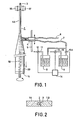
- Fig. 1 shows schematically an arrangement for applying a layer of glass particles on a vertically arranged endless cylindrical starting rod 1.
- Rod 1 is formed from a number of extension members 1A, 1B, etc. which during the deposition process are fitted at regular intervals, depending on the speed of translation (the translation direction is shown in Figure 1 by means of an arrow pointing vertically down towards the bottom of the sheet).
- the extension members 1 A, and 1 B may be provided at one end with an opening having an internal screwthread 2 (see Fig. 2) while the other end has a reduced diameter over a small part of its length and is externally provided with a screwthread 3.
- the extension members may consist of quartz, ceramic material (for example sintered AI 2 0 3 ), carbon or of a metal coated with a Si0 2 or carbon layer or another material which prevents diffusion of metal ions into the deposited glass.
- the arrangement shown in Fig. 1 has a burner 4 (flame hydrolysis burner) which can be reciprocated in a programmed manner along a vertical path 5.
- the burner 4 is connected by means of flexible pipes 6 and 7 to a gas supply arrangement which is partly shown in Fig. 1.
- a mixture of a combustible gas (H 2 , CH 4 ) with oxygen is supplied to the burner 4 via the pipe 6.
- a mixture of oxygen and vapours of materials which, when reacted with oxygen form glass particles is fed via the flexible pipe 7 is the burner 4.
- Fig. 1 further shows schematically two containers 8 and 9 (the number of containers may of course be larger depending on the number of dopants one wants to use).
- Container 8 holds SiCI 4 and container 9 holds GeCl 4 .
- Oxygen is bubbled through the liquids via supply pipes 10 and 11.
- These supply pipes comprise controllable valves and controllers 12 and 13, 13A which are commonly referred to as mass flow controllers, by means of which it is possible to control the flow rate of the oxygen and consequently the quantities of metered SiCI 4 and GeC1 4 accurately by means of a control unit 14.
- the oxygen-vapour mixture is fed to the burner 4 via the pipe 7. Glass particles formed in the burner 4 are deposited onto the rod 1.
- the rod 1 is supported by a rotating table 15 and is rotated by three supporting wheels two of which, 16 and 17, are shown in Figure 1; the table 1 is translated vertically downwards.
- Fig. 1 shows one burner, it is however advantageous to arrange several burners, for example three burners, around the cylindrical starting rod, the burners are always supplied with the same gas-vapour mixture.
- Fig. 3 shows such an arrangement.
- Three burners 4A, 4B and 4C are fitted on a ring 26 which is connected to three rods 27, 28 and 29 which can be moved by means of a drive, not shown.
- the reference numerals in Figure 3 have the same meaning as in Figure 1.
- the burners 4A, 4B and 4C move simultaneously along the starting rod 1. It may be advantageous if the burners are not arranged in the same plane perpendicularly to the starting rod, but are so disposed with respect to each other that three layers are deposited on top of each other.
- the burners shown in Fig. 3 are directed at an angle of 120° with respect to each other at the starting rod.
- Fig. 4 shows schematically the variation of the dopant concentration. According as the deposited path of glass particles approaches closer to the starting rod 1 the dopant concentration D increases. Thereafter a second path is deposited on the last path, the dopant concentration remains the same, thereafter the dopant concentration decreases again. In this way a graded index fibre can be obtained.
- the diameter of the preform is indicated by d.
- Fig. 5 shows schematically the variation of the dopant concentration D during the manufacture of a stepped index fibre. After an initially low level (cladding) the dopant concentration increases to a higher value (core), remains constant for some time and decreases thereafter again.
- the length of an extension member consisting of sintered AI 2 0 3 is: 100 cm and its diameter 2 cm.
- the burner which deposits a 1 cm wide path of glass particles reciprocates over a distance of 40 cm at a speed of 4 cm per sec., the rotational speed of the starting rod 1 is then 4 revolutions per sec. and the translation speed 0.1 cm/sec.
- a preform 20 having a total diameter of 10 cm is obtained. At regular intervals a portion of the preform 20 is cut off, for example having a length of 100 cm.
- the starting rod 1 contained in this preform portion is removed and the preform is sintered in a customary manner and drawn into a fibre, for example in the manner as described in USP 3,826,560.
Landscapes
- Chemical & Material Sciences (AREA)
- Engineering & Computer Science (AREA)
- Chemical Kinetics & Catalysis (AREA)
- General Chemical & Material Sciences (AREA)
- Life Sciences & Earth Sciences (AREA)
- General Life Sciences & Earth Sciences (AREA)
- Geochemistry & Mineralogy (AREA)
- Manufacturing & Machinery (AREA)
- Materials Engineering (AREA)
- Organic Chemistry (AREA)
- Manufacture, Treatment Of Glass Fibers (AREA)
Claims (6)
Applications Claiming Priority (2)
| Application Number | Priority Date | Filing Date | Title |
|---|---|---|---|
| NL8103647 | 1981-08-03 | ||
| NL8103647A NL8103647A (nl) | 1981-08-03 | 1981-08-03 | Werkwijze voor de continue vervaardiging van een optische fiber onder neerslaan van glaslagen op een doorn. |
Publications (2)
| Publication Number | Publication Date |
|---|---|
| EP0072071A1 EP0072071A1 (de) | 1983-02-16 |
| EP0072071B1 true EP0072071B1 (de) | 1985-02-06 |
Family
ID=19837886
Family Applications (1)
| Application Number | Title | Priority Date | Filing Date |
|---|---|---|---|
| EP19820200966 Expired EP0072071B1 (de) | 1981-08-03 | 1982-07-28 | Verfahren zur kontinuierlichen Herstellung von Vorformen zum Ziehen von optischen Fasern durch niederschlag von Glasfilms auf einen zylindrischen Ausgangsstab |
Country Status (4)
| Country | Link |
|---|---|
| EP (1) | EP0072071B1 (de) |
| JP (1) | JPS5826044A (de) |
| DE (1) | DE3262219D1 (de) |
| NL (1) | NL8103647A (de) |
Family Cites Families (5)
| Publication number | Priority date | Publication date | Assignee | Title |
|---|---|---|---|---|
| NL165134B (nl) * | 1974-04-24 | 1980-10-15 | Nippon Telegraph & Telephone | Werkwijze voor de vervaardiging van een staaf als tussenprodukt voor de vervaardiging van een optische vezel en werkwijze voor de vervaardiging van een optische vezel uit zulk een tussenprodukt. |
| FR2447890B1 (fr) * | 1979-02-05 | 1985-06-28 | Lyonnaise Transmiss Optiques | Procede de fabrication de preformes de fibres optiques a gradient d'indice, et dispositif de mise en oeuvre de ce procede |
| US4230472A (en) * | 1979-02-22 | 1980-10-28 | Corning Glass Works | Method of forming a substantially continuous optical waveguide |
| US4289517A (en) * | 1980-07-03 | 1981-09-15 | Corning Glass Works | Method of forming an optical waveguide preform |
| FR2487811B1 (fr) * | 1980-07-31 | 1985-07-26 | France Etat | Procede et installation de fabrication de fibres optiques en continu |
-
1981
- 1981-08-03 NL NL8103647A patent/NL8103647A/nl not_active Application Discontinuation
-
1982
- 1982-07-28 EP EP19820200966 patent/EP0072071B1/de not_active Expired
- 1982-07-28 DE DE8282200966T patent/DE3262219D1/de not_active Expired
- 1982-07-31 JP JP13300482A patent/JPS5826044A/ja active Pending
Also Published As
| Publication number | Publication date |
|---|---|
| NL8103647A (nl) | 1983-03-01 |
| EP0072071A1 (de) | 1983-02-16 |
| DE3262219D1 (en) | 1985-03-21 |
| JPS5826044A (ja) | 1983-02-16 |
Similar Documents
| Publication | Publication Date | Title |
|---|---|---|
| US4135901A (en) | Method of manufacturing glass for optical waveguide | |
| EP0026625B1 (de) | Verfahren und Apparat zur Herstellung einer Mehrkomponenten-Glasfaser-Vorform | |
| US4440558A (en) | Fabrication of optical preforms by axial chemical vapor deposition | |
| EP0067050B1 (de) | Verfahren zur Herstellung eines optischen Wellenleiters | |
| EP0082642B1 (de) | Verfahren und Vorrichtung zur Herstellung einer Glasröhre | |
| US4259101A (en) | Method for producing optical fiber preform | |
| RU2235071C2 (ru) | Способ изготовления заготовки оптического волокна | |
| US4304581A (en) | Lightguide preform fabrication | |
| US4155733A (en) | Optical fibre manufacture | |
| US4642129A (en) | Method for manufacturing preforms of glass for optical fibers | |
| EP0150247B1 (de) | Verfahren zur Herstellung von Vorformen für optische Fasern | |
| CN1197798C (zh) | 一种制备光纤预制棒的方法 | |
| CN101987778A (zh) | 一种制造用于光纤的初级预制棒的方法 | |
| EP0072071B1 (de) | Verfahren zur kontinuierlichen Herstellung von Vorformen zum Ziehen von optischen Fasern durch niederschlag von Glasfilms auf einen zylindrischen Ausgangsstab | |
| CN1111514C (zh) | 一种制作大型光纤预制棒的方法 | |
| EP1440949A1 (de) | Verfahren zur herstellung von grundmaterial für lichtleitfasern | |
| US4341541A (en) | Process for the production of optical fiber | |
| KR20000013544A (ko) | 고품질의 광섬유용 프리폼 제조장치 및 방법 | |
| CN209442875U (zh) | Vad制备光纤预制棒的装置 | |
| JPS6012981B2 (ja) | 光フアイバ母材の製造法 | |
| JPH0525818B2 (de) | ||
| EP0135175B1 (de) | Verfahren zum Herstellen einer optischen Faservorform und optische Fasern hergestellt in diesem Verfahren | |
| JP4140839B2 (ja) | 光ファイバ母材の製造方法 | |
| JP2000063141A (ja) | 光ファイバ用多孔質ガラス母材の製造方法 | |
| NL8302641A (nl) | Werkwijze voor het vervaardigen van vooraf gevormde optische vezellichamen. |
Legal Events
| Date | Code | Title | Description |
|---|---|---|---|
| PUAI | Public reference made under article 153(3) epc to a published international application that has entered the european phase |
Free format text: ORIGINAL CODE: 0009012 |
|
| 17P | Request for examination filed |
Effective date: 19820728 |
|
| AK | Designated contracting states |
Designated state(s): DE FR GB NL |
|
| GRAA | (expected) grant |
Free format text: ORIGINAL CODE: 0009210 |
|
| AK | Designated contracting states |
Designated state(s): DE FR GB NL |
|
| REF | Corresponds to: |
Ref document number: 3262219 Country of ref document: DE Date of ref document: 19850321 |
|
| ET | Fr: translation filed | ||
| PLBE | No opposition filed within time limit |
Free format text: ORIGINAL CODE: 0009261 |
|
| STAA | Information on the status of an ep patent application or granted ep patent |
Free format text: STATUS: NO OPPOSITION FILED WITHIN TIME LIMIT |
|
| 26N | No opposition filed | ||
| PGFP | Annual fee paid to national office [announced via postgrant information from national office to epo] |
Ref country code: GB Payment date: 19900702 Year of fee payment: 9 |
|
| PGFP | Annual fee paid to national office [announced via postgrant information from national office to epo] |
Ref country code: FR Payment date: 19900720 Year of fee payment: 9 |
|
| PGFP | Annual fee paid to national office [announced via postgrant information from national office to epo] |
Ref country code: NL Payment date: 19900731 Year of fee payment: 9 |
|
| PGFP | Annual fee paid to national office [announced via postgrant information from national office to epo] |
Ref country code: DE Payment date: 19900921 Year of fee payment: 9 |
|
| PG25 | Lapsed in a contracting state [announced via postgrant information from national office to epo] |
Ref country code: GB Effective date: 19910728 |
|
| PG25 | Lapsed in a contracting state [announced via postgrant information from national office to epo] |
Ref country code: NL Effective date: 19920201 |
|
| NLV4 | Nl: lapsed or anulled due to non-payment of the annual fee | ||
| GBPC | Gb: european patent ceased through non-payment of renewal fee | ||
| PG25 | Lapsed in a contracting state [announced via postgrant information from national office to epo] |
Ref country code: FR Effective date: 19920331 |
|
| PG25 | Lapsed in a contracting state [announced via postgrant information from national office to epo] |
Ref country code: DE Effective date: 19920401 |
|
| REG | Reference to a national code |
Ref country code: FR Ref legal event code: ST |