EP0071784B1 - Dispositif gyroscopique comprenant un gyroscope méridien à une suspension par lien - Google Patents
Dispositif gyroscopique comprenant un gyroscope méridien à une suspension par lien Download PDFInfo
- Publication number
- EP0071784B1 EP0071784B1 EP82106319A EP82106319A EP0071784B1 EP 0071784 B1 EP0071784 B1 EP 0071784B1 EP 82106319 A EP82106319 A EP 82106319A EP 82106319 A EP82106319 A EP 82106319A EP 0071784 B1 EP0071784 B1 EP 0071784B1
- Authority
- EP
- European Patent Office
- Prior art keywords
- gyro
- signal
- housing
- assembly
- torque
- Prior art date
- Legal status (The legal status is an assumption and is not a legal conclusion. Google has not performed a legal analysis and makes no representation as to the accuracy of the status listed.)
- Expired
Links
Images


Classifications
-
- G—PHYSICS
- G01—MEASURING; TESTING
- G01C—MEASURING DISTANCES, LEVELS OR BEARINGS; SURVEYING; NAVIGATION; GYROSCOPIC INSTRUMENTS; PHOTOGRAMMETRY OR VIDEOGRAMMETRY
- G01C19/00—Gyroscopes; Turn-sensitive devices using vibrating masses; Turn-sensitive devices without moving masses; Measuring angular rate using gyroscopic effects
- G01C19/02—Rotary gyroscopes
- G01C19/34—Rotary gyroscopes for indicating a direction in the horizontal plane, e.g. directional gyroscopes
- G01C19/38—Rotary gyroscopes for indicating a direction in the horizontal plane, e.g. directional gyroscopes with north-seeking action by other than magnetic means, e.g. gyrocompasses using earth's rotation
Definitions
- DE-A 1 941 808 discloses a gyroscope for determining the north direction with a meridian gyroscope suspended from a band in a housing, in which a tap for generating a signal in accordance with the azumite deflection of the gyroscope relative to a housing reference given by the band zero position is provided.
- a torque generator acts on the meridian gyro, which is acted upon by the signal of the tap via a high-gain amplifier. This torque generator exerts a torque about the azimuth axis on the meridian gyro, which corresponds to the gyro directional torque, i. H.
- the Meridian gyroscope is electrically connected to the housing reference, i.e. H. the band zero, tied up.
- the torque to be exerted on the meridian gyro is proportional to the gyro directional torque and thus, at small angles between the gyro swirl axis and north, is proportional to this angle. If one can also neglect the angle between the gyroscopic swirl axis and the housing reference with a sufficiently high amplification of the signal provided by the tap, the torque of the torque generator is proportional to the angle between the housing reference and north. If one can assume that the torque generator works linearly, the amplified signal of the tap, which is applied to the torque generator, provides a measure of this angle between the housing reference and the north. This signal can be used to indicate the north direction (DE-B 2 008 702) or for navigation purposes (DE-B 2 545 025).
- the oscillation period of the system is significantly shortened by the electrical restraint of the meridian gyro.
- the north deviation i.e. the north deviation
- H the angle between device reference and north can be determined.
- the invention has for its object to eliminate these non-stochastic disorders.
- this "disturbance torque" is determined by the accelerometer and the model, and the disturbance torque signal thus obtained is used to correct the measurement.
- the gyroscope contains a device housing 10, in which a gyroscope is suspended in a gyroscope housing 12 with a mast 14 by means of a band 16.
- the device housing 10 defines a coordinate system with a vertical axis z and the axes x and y perpendicular thereto and to one another.
- a device reference 17 is a direction parallel to the y axis.
- With 18 the substantially horizontal gyro swirl axis of the gyro mounted in the gyro housing 12 is designated. If the gyro with its gyro swirl axis 18 lies in the plane defined by the y and z axes, i. H.
- the gyro twist axis 18 coincides with the housing reference, the band 16 is relaxed. This position is therefore called zero band.
- the deflection of the gyro housing 12 with respect to the housing reference 17 is detected by means of a tap 20 indicated here as a potentiometer.
- the signal of the tap 20 is connected to a torque generator 24 via a high-gain amplifier 22.
- Two accelerometers 28 and 30 are seated on the device housing 10 in the area of the belt suspension 26.
- the sensitivity axis of the accelerometer 28, indicated by an arrow is parallel to the housing reference 17 and thus to the gyro twist axis 18 in its captive position.
- the sensitivity axis of the accelerometer 30 indicated by an arrow is horizontal and transverse to the sensitivity axis of the accelerometer 28 and to the gyro twist axis 18.
- the sensitivity axes of both accelerometers 28 and 30 are perpendicular to the direction of the band 16.
- Signals in the computer that represent a measured variable are marked with the same symbol as this, but with a snake ( ⁇ ).
- Estimated values of a measured variable are identified by a roof (") above the variable.
- the effect of simultaneous vibrations of the belt suspension 26 in the direction of the x-axis and the y-axis can be derived from FIG. 2. If the band suspension 26 moves in the direction of the x-axis, the mast 14 is deflected from the vertical by the angle y in the x-z plane. If the belt suspension 26 is simultaneously accelerated in the direction of the y axis, an acceleration force my occurs at the center of gravity S of the gyroscope and gyro housing 12. This acceleration force acts on the lever arm r. y and generates a moment around the vertical axis
- the movements of the suspension 26 are harmonic vibrations in both the x-axis and the y-axis directions.
- the belt suspension 26 is then deflected in the direction of the x-axis on the opposite side (to the front in FIG. 2).
- the center of gravity S is then on the opposite side of the vertical 32 passing through the upper end of the mast 14 (behind this in FIG. 2).
- the acceleration y in the direction of the y axis is also in phase opposition to the direction shown in FIG. 2. In both cases, this results in a moment about the vertical axis, which in the present case acts clockwise as seen from above in FIG. 2.
- a "rectifier effect" occurs, which means that a torque around the vertical axis is always effective in one direction, even with harmonic vibrations.
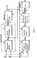
- RRL WORLD a block diagram is shown, which illustrates the behavior of the gyroscope shown in FIG. 1.
- COMPTER the various possibilities of signal processing are shown, by means of which the influence of the described disturbing torques is eliminated.
- block 34 represents the gyroscopic movement that leads to an angle a in azimuth. If the gyro housing 12 deviates from the device reference 17, which forms the angle a o with the north direction, the tap 20 supplies the signal ⁇ A. This is represented by a summation point 36. The signal is amplified by amplifier 22, represented by block 38.
- the timing behavior of the amplifier is due to a transfer function shown.
- the amplifier 22 supplies the signal Mg, which depends on a o . This signal is fed back to the input of block 34 and takes effect at a summing point 40 with a negative sign. This symbolizes the attachment of the gyroscope to the housing reference 17 by the torque generator 24.
- Accelerations aMx and aMy are effective on the belt suspension 26 in the direction of the x-axis and in the direction of the y-axis.
- these accelerations aMx and aMy generate a disturbance torque M ⁇ which is effective at the gyroscope about the vertical axis. This is indicated by adding the torque M a to the torque Mg of the torque generator 24 in the summing point 40.
- This disturbance torque M a influences the movement of the gyroscope, which is why the signal Mg depends not only on a o but also on M a .
- the accelerations on and aMy are measured by accelerometers 30 and 28, respectively.
- the accelerometer signals are fed to a computer 44. This is indicated by lines 46 and 48.
- the computer 44 contains a model of the disturbance torque dynamics, which is represented by a block 50.
- the accelerometer signals aMx and aMy are applied to this model. It supplies an interference torque signal M Q which corresponds to the interference torque M a .
- the mean value M ⁇ ⁇ G of the disturbance torque signal M ⁇ ⁇ is formed in the computer 44.
- This disturbance torque mean signal M aG was multiplied by a factor taking into account the gain of the torque generator 24, as represented by block 54.
- Means are provided for subtracting the signal Mg (M ⁇ G ) thus obtained from the compensation signal Mg ( ⁇ o , M ⁇ ), which is also connected to the computer 44. These means of subtraction are through the Summing point 56 shown in Fig. 3. At this summing point 56 there is an output signal Mg (a o ) corrected with regard to the interference torques.
- This output signal Mg (a o ) is connected to a filter 58, for example an average filter according to US Pat. No. 4,075,764, which supplies an output signal ⁇ o .
- This output signal is an estimate of the angle between the housing reference 17 and north.
- the disturbance torque M a real affects the movement of the gyroscope. Its influence is taken into account in the computer 44 during signal processing. This means that not every variation in the disturbance torque is compensated for, but only the »direct component « that is included in the measurement. One can speak of a "static compensation" of the rectifier effect.
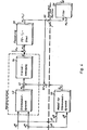
- the representation of the "real world" of the gyroscope is the same as in Fig. 3. Corresponding parts are provided with the same reference numerals as there. It is also generated in the computer 60 in the same way as in FIG. 3 from the accelerometer signals and a model 50 for the disturbance torque dynamics won a disturbance torque signal M ⁇ ⁇ . However, this interference torque signal M ⁇ ⁇ is superimposed here in a summing point 62 on the compensation signal Mg ( ⁇ o ) of the captive circuit, which is connected to the torque generator 24. The interference torque signal M ⁇ ⁇ is therefore not only taken into account in the calculation, but it intervenes in the movement of the real gyroscope and counteracts the actually effective interference torque M a via the torque generator 24. The movement of the gyro and the compensation signal Mg do not contain any components caused by the disturbance torque. This compensation signal Mg (a o ) is again applied to a filter 58.
- the interference torque M a is compensated dynamically in the computer 64, ie not only the influence of the direct component of the interference torque is compensated, but every instantaneous value.
- the representation of the “real world” of the gyroscope is the same as in FIGS. 3 and 4.
- the computer 64 contains a model 50 for the disturbance torque dynamics, to which the accelerometer signals aMx and aMy are connected, and that provides an interference torque signal M a .
- the computer 64 also contains a model 66 for the gyroscopic movement, which delivers an output signal ⁇ .
- the signal ⁇ A obtained at the summing point 68 is passed to a filter 72 which has the same transfer function as the amplifier 22.
- the output signal of the filter 72 corresponds in the model to the signal that would have to be applied to the torque generator 24 at any moment in order to compensate for the disturbance torque M a .
- This signal is subtracted from the compensation signal actually applied to the torque generator 24 at the summing point 74.
- the result is a signal Mg (a o ) which is not influenced by the disturbing moments M a .
- This signal is switched to a filter 58 similar to FIGS. 3 and 4, which provides an estimate a o for the angle between device reference 17 and north.
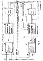
- a Kalman filter 76 is provided.
- the real world of the gyroscope is represented by a block 78, which (like block 42) symbolizes the disturbance torque dynamics of the system, after which the acceleration aMx and aMy led to a disturbance torque M a .
- a block 80 represents the movement of the gyroscope in FIG. 1. Measured variables result (possibly only one measured variable), as represented by a block 82 “measurement matrix”. These measured variables are compared in the Kalman filter 76 at 84 with estimated values of these measured variables. These estimates are provided by a discrete model 86 for the movement of the bound gyroscope, as indicated by block 88 "measurement matrix”. The differences between the measured variables and the estimated values are multiplied by time-dependent factors K (t k ), which are represented by block 90, applied to the model 86 and change its parameters until the differences disappear.
- K time-dependent factors
- the Kaiman filter 76 can use the difference between the compensation signal Mg and its estimated value Mg as well as the difference between the deviation a A of the gyro from the housing reference and the estimated value ⁇ A of this deviation as the filter input variable.
- the computer 92 also contains a model 94 for the disturbance torque dynamics, to which the accelerometer signals aMx and aMy are connected and which supplies a disturbance torque signal M a .
- This disturbance torque signal M a is applied as a deterministic input to model 86 for the movement of the bound gyro.
- the angle ⁇ o is taken as an estimate ⁇ 0 on the model 86.
Landscapes
- Life Sciences & Earth Sciences (AREA)
- Environmental & Geological Engineering (AREA)
- General Life Sciences & Earth Sciences (AREA)
- Geology (AREA)
- Physics & Mathematics (AREA)
- Engineering & Computer Science (AREA)
- General Physics & Mathematics (AREA)
- Radar, Positioning & Navigation (AREA)
- Remote Sensing (AREA)
- Gyroscopes (AREA)
Claims (5)
caractérisé par le fait que
Applications Claiming Priority (2)
| Application Number | Priority Date | Filing Date | Title |
|---|---|---|---|
| DE3131110A DE3131110C1 (de) | 1981-08-06 | 1981-08-06 | Kreiselgeraet mit einem bandaufgehaengten Meridiankreisel |
| DE3131110 | 1981-08-06 |
Publications (2)
| Publication Number | Publication Date |
|---|---|
| EP0071784A1 EP0071784A1 (fr) | 1983-02-16 |
| EP0071784B1 true EP0071784B1 (fr) | 1985-11-13 |
Family
ID=6138701
Family Applications (1)
| Application Number | Title | Priority Date | Filing Date |
|---|---|---|---|
| EP82106319A Expired EP0071784B1 (fr) | 1981-08-06 | 1982-07-14 | Dispositif gyroscopique comprenant un gyroscope méridien à une suspension par lien |
Country Status (2)
| Country | Link |
|---|---|
| EP (1) | EP0071784B1 (fr) |
| DE (2) | DE3131110C1 (fr) |
Families Citing this family (2)
| Publication number | Priority date | Publication date | Assignee | Title |
|---|---|---|---|---|
| DE3836417A1 (de) * | 1988-10-26 | 1990-05-03 | Bodenseewerk Geraetetech | Filteranordnung zur erzeugung eines schaetzwertes einer durch stoerungen beeinflussten messgroesse |
| CN110906921B (zh) * | 2019-12-11 | 2021-11-23 | 株洲菲斯罗克光电科技股份有限公司 | 一种光纤陀螺生产用检测装置 |
Family Cites Families (7)
| Publication number | Priority date | Publication date | Assignee | Title |
|---|---|---|---|---|
| DE1941808A1 (de) * | 1969-08-16 | 1971-02-25 | Bodenseewerk Geraetetech | Nordsuchendes Kreiselpendel |
| DE2008702C3 (de) * | 1970-02-25 | 1978-11-23 | Bodenseewerk Geraetetechnik Gmbh, 7770 Ueberlingen | Nordsuchendes Kreiselpendel |
| DE2545025B2 (de) * | 1975-10-08 | 1980-09-11 | Bodenseewerk Geraetetechnik Gmbh, 7770 Ueberlingen | Navigationsgerät zur Navigation von Landfahrzeugen |
| DE2545026A1 (de) * | 1975-10-08 | 1977-04-14 | Bodenseewerk Geraetetech | Geraet zur bestimmung der nordrichtung |
| DE2618868A1 (de) * | 1976-04-29 | 1977-11-17 | Bodenseewerk Geraetetech | Geraet zur bestimmung der nordrichtung |
| DE2741274C3 (de) * | 1977-09-14 | 1980-07-31 | Bodenseewerk Geraetetechnik Gmbh, 7770 Ueberlingen | Gerät zur automatischen Bestimmung der Nordrichtung |
| DE2922411A1 (de) * | 1979-06-01 | 1980-12-04 | Bodenseewerk Geraetetech | Geraet zur automatischen bestimmung der nordrichtung in einem fahrzeug |
-
1981
- 1981-08-06 DE DE3131110A patent/DE3131110C1/de not_active Expired
-
1982
- 1982-07-14 DE DE8282106319T patent/DE3267416D1/de not_active Expired
- 1982-07-14 EP EP82106319A patent/EP0071784B1/fr not_active Expired
Also Published As
| Publication number | Publication date |
|---|---|
| EP0071784A1 (fr) | 1983-02-16 |
| DE3267416D1 (en) | 1985-12-19 |
| DE3131110C1 (de) | 1983-02-24 |
Similar Documents
| Publication | Publication Date | Title |
|---|---|---|
| DE10228639A1 (de) | Hybrid-Trägheitsnavigationsverfahren und -Vorrichtung | |
| DE3431593A1 (de) | Signalverarbeitungsvorrichtung fuer einen auf einem beschleunigungsmesser beruhenden winkelgeschwindigkeitsfuehler | |
| DE10219861A1 (de) | Verfahren und Vorrichtung zur Langzeitnavigation | |
| DE2741274C3 (de) | Gerät zur automatischen Bestimmung der Nordrichtung | |
| DE3143527C2 (de) | Gerät zur automatischen Bestimmung der Nordrichtung | |
| DE2310767B2 (de) | Einrichtung zur Stabilisierung einer in einem Kardanrahmen aufgehängten Plattform | |
| DE2922414C2 (de) | Kurs-Lage-Referenzgerät | |
| DE2554519A1 (de) | Antriebsvorrichtung fuer einen rotor | |
| DE2922415C2 (de) | Navigationsgerät für Landfahrzeuge | |
| EP0322532B1 (fr) | Dispositif pour la détermination de la vitesse des véhicules | |
| DE2922411C2 (fr) | ||
| DE3131111C2 (de) | Kreiselgerät zur Bestimmung der Nordrichtung | |
| EP0071784B1 (fr) | Dispositif gyroscopique comprenant un gyroscope méridien à une suspension par lien | |
| EP0223159B1 (fr) | Appareil pour indiquer le Nord | |
| DE2754497A1 (de) | Einrichtung fuer ein servosystem mit geschlossenem kreis | |
| DE3033280C2 (de) | Kurs-Lage-Referenzgerät | |
| DE2744431C2 (de) | Navigationsgerät zur Navigation von Landfahrzeugen | |
| DE3141836C2 (fr) | ||
| DE2731134A1 (de) | Lotsensor | |
| CH635428A5 (de) | Vorrichtung zur bestimmung der lotrichtung in einem auf einer bewegbaren unterlage angebrachten system. | |
| DE3141342C2 (de) | Kurs-Lage-Referenzgerät mit zweiachsiger Plattform | |
| DE3214379C2 (de) | Vorrichtung zur magnetischen Lageregelung eines Satelliten | |
| EP0106066A2 (fr) | Appareil pour déterminer le nord | |
| EP0411565B1 (fr) | Dispositif gyroscopique orientable automatiquement avec une plate-forme à deux axes | |
| DE19532122C1 (de) | Verfahren zur Horizontstabilisierung von Magnetkompassen |
Legal Events
| Date | Code | Title | Description |
|---|---|---|---|
| PUAI | Public reference made under article 153(3) epc to a published international application that has entered the european phase |
Free format text: ORIGINAL CODE: 0009012 |
|
| AK | Designated contracting states |
Designated state(s): CH DE FR GB LI |
|
| 17P | Request for examination filed |
Effective date: 19830408 |
|
| GRAA | (expected) grant |
Free format text: ORIGINAL CODE: 0009210 |
|
| AK | Designated contracting states |
Designated state(s): CH DE FR GB LI |
|
| REF | Corresponds to: |
Ref document number: 3267416 Country of ref document: DE Date of ref document: 19851219 |
|
| ET | Fr: translation filed | ||
| PLBE | No opposition filed within time limit |
Free format text: ORIGINAL CODE: 0009261 |
|
| STAA | Information on the status of an ep patent application or granted ep patent |
Free format text: STATUS: NO OPPOSITION FILED WITHIN TIME LIMIT |
|
| 26N | No opposition filed | ||
| PGFP | Annual fee paid to national office [announced via postgrant information from national office to epo] |
Ref country code: FR Payment date: 19930630 Year of fee payment: 12 |
|
| PGFP | Annual fee paid to national office [announced via postgrant information from national office to epo] |
Ref country code: GB Payment date: 19930701 Year of fee payment: 12 |
|
| PGFP | Annual fee paid to national office [announced via postgrant information from national office to epo] |
Ref country code: CH Payment date: 19930902 Year of fee payment: 12 |
|
| PGFP | Annual fee paid to national office [announced via postgrant information from national office to epo] |
Ref country code: DE Payment date: 19930927 Year of fee payment: 12 |
|
| PG25 | Lapsed in a contracting state [announced via postgrant information from national office to epo] |
Ref country code: GB Effective date: 19940714 |
|
| PG25 | Lapsed in a contracting state [announced via postgrant information from national office to epo] |
Ref country code: LI Effective date: 19940731 Ref country code: CH Effective date: 19940731 |
|
| GBPC | Gb: european patent ceased through non-payment of renewal fee |
Effective date: 19940714 |
|
| PG25 | Lapsed in a contracting state [announced via postgrant information from national office to epo] |
Ref country code: FR Effective date: 19950331 |
|
| REG | Reference to a national code |
Ref country code: CH Ref legal event code: PL |
|
| PG25 | Lapsed in a contracting state [announced via postgrant information from national office to epo] |
Ref country code: DE Effective date: 19950401 |
|
| REG | Reference to a national code |
Ref country code: FR Ref legal event code: ST |