EP0071419A1 - Combustion apparatus with reduced nitrogen oxide emission - Google Patents
Combustion apparatus with reduced nitrogen oxide emission Download PDFInfo
- Publication number
- EP0071419A1 EP0071419A1 EP82303878A EP82303878A EP0071419A1 EP 0071419 A1 EP0071419 A1 EP 0071419A1 EP 82303878 A EP82303878 A EP 82303878A EP 82303878 A EP82303878 A EP 82303878A EP 0071419 A1 EP0071419 A1 EP 0071419A1
- Authority
- EP
- European Patent Office
- Prior art keywords
- fuel
- coolant
- combustor
- air
- liquid
- Prior art date
- Legal status (The legal status is an assumption and is not a legal conclusion. Google has not performed a legal analysis and makes no representation as to the accuracy of the status listed.)
- Granted
Links
- 238000002485 combustion reaction Methods 0.000 title claims abstract description 57
- MWUXSHHQAYIFBG-UHFFFAOYSA-N Nitric oxide Chemical compound O=[N] MWUXSHHQAYIFBG-UHFFFAOYSA-N 0.000 title claims description 36
- 239000000446 fuel Substances 0.000 claims abstract description 227
- 239000002826 coolant Substances 0.000 claims abstract description 74
- 239000007788 liquid Substances 0.000 claims abstract description 65
- 239000000203 mixture Substances 0.000 claims abstract description 18
- 238000002347 injection Methods 0.000 claims description 73
- 239000007924 injection Substances 0.000 claims description 73
- 239000007789 gas Substances 0.000 claims description 54
- XLYOFNOQVPJJNP-UHFFFAOYSA-N water Chemical group O XLYOFNOQVPJJNP-UHFFFAOYSA-N 0.000 claims description 29
- 238000000034 method Methods 0.000 claims description 17
- 238000000889 atomisation Methods 0.000 claims description 15
- 238000009826 distribution Methods 0.000 claims description 7
- 239000008367 deionised water Substances 0.000 claims description 2
- 229910021641 deionized water Inorganic materials 0.000 claims description 2
- 230000001737 promoting effect Effects 0.000 claims 2
- 239000003570 air Substances 0.000 abstract 2
- 230000015572 biosynthetic process Effects 0.000 description 7
- IJGRMHOSHXDMSA-UHFFFAOYSA-N Atomic nitrogen Chemical compound N#N IJGRMHOSHXDMSA-UHFFFAOYSA-N 0.000 description 6
- 230000008901 benefit Effects 0.000 description 5
- 230000007423 decrease Effects 0.000 description 5
- 230000009467 reduction Effects 0.000 description 5
- 239000010408 film Substances 0.000 description 4
- 238000011144 upstream manufacturing Methods 0.000 description 4
- 229910052757 nitrogen Inorganic materials 0.000 description 3
- 238000009827 uniform distribution Methods 0.000 description 3
- 238000006243 chemical reaction Methods 0.000 description 2
- 230000001419 dependent effect Effects 0.000 description 2
- 230000009977 dual effect Effects 0.000 description 2
- VNWKTOKETHGBQD-UHFFFAOYSA-N methane Chemical compound C VNWKTOKETHGBQD-UHFFFAOYSA-N 0.000 description 2
- 239000010409 thin film Substances 0.000 description 2
- 239000004215 Carbon black (E152) Substances 0.000 description 1
- UGFAIRIUMAVXCW-UHFFFAOYSA-N Carbon monoxide Chemical compound [O+]#[C-] UGFAIRIUMAVXCW-UHFFFAOYSA-N 0.000 description 1
- RWSOTUBLDIXVET-UHFFFAOYSA-N Dihydrogen sulfide Chemical compound S RWSOTUBLDIXVET-UHFFFAOYSA-N 0.000 description 1
- QVGXLLKOCUKJST-UHFFFAOYSA-N atomic oxygen Chemical compound [O] QVGXLLKOCUKJST-UHFFFAOYSA-N 0.000 description 1
- 229910002091 carbon monoxide Inorganic materials 0.000 description 1
- 230000015556 catabolic process Effects 0.000 description 1
- 238000004140 cleaning Methods 0.000 description 1
- 230000008878 coupling Effects 0.000 description 1
- 238000010168 coupling process Methods 0.000 description 1
- 238000005859 coupling reaction Methods 0.000 description 1
- 230000003247 decreasing effect Effects 0.000 description 1
- 238000006731 degradation reaction Methods 0.000 description 1
- 239000002283 diesel fuel Substances 0.000 description 1
- 238000007599 discharging Methods 0.000 description 1
- 230000000694 effects Effects 0.000 description 1
- 238000010894 electron beam technology Methods 0.000 description 1
- 239000003344 environmental pollutant Substances 0.000 description 1
- 230000008020 evaporation Effects 0.000 description 1
- 238000001704 evaporation Methods 0.000 description 1
- 239000012634 fragment Substances 0.000 description 1
- 239000008240 homogeneous mixture Substances 0.000 description 1
- 229930195733 hydrocarbon Natural products 0.000 description 1
- 150000002430 hydrocarbons Chemical class 0.000 description 1
- 229910000037 hydrogen sulfide Inorganic materials 0.000 description 1
- 230000002401 inhibitory effect Effects 0.000 description 1
- 229910052500 inorganic mineral Inorganic materials 0.000 description 1
- 238000007689 inspection Methods 0.000 description 1
- 238000009434 installation Methods 0.000 description 1
- 230000007246 mechanism Effects 0.000 description 1
- 239000011707 mineral Substances 0.000 description 1
- 239000003345 natural gas Substances 0.000 description 1
- 230000003647 oxidation Effects 0.000 description 1
- 238000007254 oxidation reaction Methods 0.000 description 1
- 239000001301 oxygen Substances 0.000 description 1
- 229910052760 oxygen Inorganic materials 0.000 description 1
- 231100000719 pollutant Toxicity 0.000 description 1
- 239000000126 substance Substances 0.000 description 1
- 238000003466 welding Methods 0.000 description 1
Images



Classifications
-
- F—MECHANICAL ENGINEERING; LIGHTING; HEATING; WEAPONS; BLASTING
- F02—COMBUSTION ENGINES; HOT-GAS OR COMBUSTION-PRODUCT ENGINE PLANTS
- F02C—GAS-TURBINE PLANTS; AIR INTAKES FOR JET-PROPULSION PLANTS; CONTROLLING FUEL SUPPLY IN AIR-BREATHING JET-PROPULSION PLANTS
- F02C3/00—Gas-turbine plants characterised by the use of combustion products as the working fluid
- F02C3/20—Gas-turbine plants characterised by the use of combustion products as the working fluid using a special fuel, oxidant, or dilution fluid to generate the combustion products
- F02C3/30—Adding water, steam or other fluids for influencing combustion, e.g. to obtain cleaner exhaust gases
-
- F—MECHANICAL ENGINEERING; LIGHTING; HEATING; WEAPONS; BLASTING
- F23—COMBUSTION APPARATUS; COMBUSTION PROCESSES
- F23L—SUPPLYING AIR OR NON-COMBUSTIBLE LIQUIDS OR GASES TO COMBUSTION APPARATUS IN GENERAL ; VALVES OR DAMPERS SPECIALLY ADAPTED FOR CONTROLLING AIR SUPPLY OR DRAUGHT IN COMBUSTION APPARATUS; INDUCING DRAUGHT IN COMBUSTION APPARATUS; TOPS FOR CHIMNEYS OR VENTILATING SHAFTS; TERMINALS FOR FLUES
- F23L7/00—Supplying non-combustible liquids or gases, other than air, to the fire, e.g. oxygen, steam
- F23L7/002—Supplying water
-
- F—MECHANICAL ENGINEERING; LIGHTING; HEATING; WEAPONS; BLASTING
- F23—COMBUSTION APPARATUS; COMBUSTION PROCESSES
- F23C—METHODS OR APPARATUS FOR COMBUSTION USING FLUID FUEL OR SOLID FUEL SUSPENDED IN A CARRIER GAS OR AIR
- F23C2203/00—Flame cooling methods otherwise than by staging or recirculation
- F23C2203/30—Injection of tempering fluids
Definitions
- the present invention relates to methods of an and combustion apparatus for reducing the amission of nitrogen oxides, and more particularly to gas turbine engines.
- the oxides of nitrogen (NO X ) are harmful atmospheric pollutants, and limitations on the amounts of those substances that can be legally discharged into the atmosphere have and are being curtailed on national, state, and local levels. While this legislation was initially directed toward atmospheric pollution by emissions from automobile engines, it has since and is now being extended to other areas such as stationary internal combustion engines; a category which includes gas turbine engines of the industrial type.
- thermal NO x nitrogen oxides are formed by the reaction between nitrogen and oxygen in the combustion air (thermal NO x ) and by the oxidation of fuelbond nitrogen (fuel NO x ).
- This invention is principally concerned with inhibiting the formation of thermal NO x which is typically dominant.
- thermal NO x involves chemical reactions that are highly temperature dependent, doubling in rate for every 20°C increase in flame temperature at temperatures above 1800°C. Consequently, the rate .of thermal NO formation can be greatly reduced by even small decreases in flame or combustion temperature.
- This temperature reduction can be achieved by introducing a liquid coolant into the primary cumbustion zone of the combustor. This reduces the flame temperature by evaporation of the coolant and because the coolant raises the average specific heat of the combustion mixture.
- Water is one suitable coolant although others are available as is noted in U.S.-A-3,826,080.
- Deionized water or other water of high quality is preferably employed because minerals dissolved or entrained in the water could damage the combustor- liner or turbine components of the engine.
- coolant to fuel mass flow ratios of 0.6 to 1.9 are employed.
- a method of reducing the emission of nitrogen oxides generated by burning a liquid fuel in a combustor comprises separately introducing a liquid coolant and the liquid fuel into the combustor and contacting the coolant and the fuel with.a swirling stream of air to atomize the coolant and fuel and to form a combustible fuel-air mixture having.coolant uniformly distributed therein prior to the combustion of the fuel.
- the water or other coolant and the fuel are introduced into the'combustor separately with the water being supplied in the form of a film surrounded by the liquid fuel.
- This promotes uniform mixing of the water and fuel and, as a result, a uniform distribution of the water in the combustor's primary combustion zone. This is important because it inhibits the formation of local hot spots which is undesirable because the rate of thermal NO formation is so highly temperature dependent.
- coolant into the combustor of a gas turbine engine in the manner just described can be effected by supplying it through the fuel injection nozzle or nozzles typically employed in gas turbine engines.
- compressor discharge air first flowed past a swirler, can be used to form the coolant into the wanted film.
- Swirled compressor discharge air is also used to mix the coolant and fuel as they are discharged from the fuel injection nozzles and to atomize the fuel and coolant mixture as it enters the primary combustion zone.
- This novel method of supplying the coolant to the combutor has the advantages discussed above; it also makes unnecessary the high coolant injection pressures common in heretofore proposed coolant injection systems.
- the invention also includes combustion apparatus comprising a combustor in which liquid fuel can be burned, and means for reducing the emission of nitrogen oxides from the combustor, said means comprising means for separately introducing a liquid coolant and the liquid fuel into the combustor; means for there mixing the coolant with the fuel; means for atomizing the fuel and coolant; and means for forming a uniform mixture of fuel, coolant, and combustion air as the mixture enters the combustor.
- One preferred type of fuel injection nozzle through which the liquid fuel and coolant are introduced has provision for introducing air into its primary combustion air passage from an accessory compressor during start-up to promote the atomization of the fuel.
- the NO emission reducing coolant can be introduced through this same passage, thereby eliminating the complexity common to other coolant injection systems.
- the preferred form of fuel injection nozzle just discussed may also have a dual fuel capability. This permits, for example, a gas turbine engine to be operated on either a liquid fuel or on a gas fuel or on both types of fuel at the same time.
- An advantage of introducing coolant into gas turbine engine combustors in the manner discussed above is that the decrease in combustor efficiency attributable to the injection of the coolant is minimal.
- the decrease in combustor efficiency attributable to the injection of water never exceeded one percent except at the relatively unimportant no-load condition (this also means that carbon monoxide and unburned hydrocarbon emissions were low as they are proportional to combustion efficiency).
- reductions in NO emissions of up to 85 percent were obtained.
- the gas turbine referred to above has 21 fuel injection nozzles spaced evenly in a vertically oriented, annular or circular array.
- the height difference between the air assist and coolant lines or pigtails leading to the upper and lower fuel injection nozzles can produce a considerable difference between the pressure on the coolant flowing to the upper and lower nozzles.
- the manifold system used to supply liquid fuel to the fuel injection nozzles of the gas turbine engines in which NO emissions are reduced in accord with the principles of the present invention enhances the efficiency of the coolant used to suppress thermal NO x formation.
- Engine 10 includes a fifteen-stage axial flow compressor 12 with a radial-axial inlet 14.
- Inlet guide vanes 16 and stators 18 of the compressor are supported from compressor housing 20 with the guide vanes and the stators 18-1 through 18-5 of the first five stages being pivotally mounted so that they can be adjusted to control the flow of air through the compressor.
- the fifteen-stage rotor 22 of compressor 12 is composed of discs 24 with vanes 26 fixed thereto.
- the discs are joined as by electron beam welding into a single unit.
- Compressor housing 20 is split longitudinally on a vertical plane through the axial centerline of the housing into two sections 20a (only one of which is shown). This accommodates installation of the compressor rotor and facilitates access to the rotor blades, guide vanes, and stators for inspection, cleaning, and replacement.
- the high pressure air discharged from compressor 12 flows through an annular, diverging diffuser 28 into an enlarged plenum 30 and from the latter to an annular combustor 32 housed in a case 34.
- the hot gasses generated in combustor 32 are discharged into a nozzle case 42 supported in an annular turbine housing 44.
- the hot gases are expanded first through a two-stage gas producer turbine 46 and then through a twostage power turbine 48.
- Gas producer turbine 46 has internally cooled, first and second stage nozzles 50 and 52 and a two- stage rotor 54.
- the first stage 56 of gas producer turbine rotor 54 includes a disc 58 to which internally cooled, radially extending blades 60 are fixed.
- the second stage 62 includes a disc 64 with uncooled, radially extending blades 66 mounted on its periphery.
- the two stages of gas producer turbine rotor 54 are bolted to each other and, in cantilever fashion, to the rear end of a forwardly extending shaft 68.
- Shaft 68 is keyed to rear compressor hub 70 which is bolted to compressor rotor 22, thereby drive-connecting gas producer turbine 46 to the compressor rotor.
- the compressor rotor and gas producer turbine are rotatably supported by a thrust bearing 72 engaged with a front compressor hub 74 drive-connected to an accessory drive 76 and by tapered land bearings 78, 80, and 82.
- Power turbine 48 includes first and second stage nozzles 84 and 86 also supported from nozzle case 42 and a rotor 88 having a first bladed stage 90 and a second bladed stage 92 bolted together for concomitant rotation. Neither the nozzles nor the rotor are cooled.
- Rotor 88 is bolted to a shaft assembly 94 rotatably supported by tapered land bearings 96 and 98 and by a thrust bearing 100.
- the shaft assembly is connected through a coupling 102 to an output shaft assembly 104 which is the input for a generator, booster compressor, mechanical drive, or other driven unit.
- Another major component of turbine engine 10 is an exhaust duct 106 for the gases discharged from the power turbine.
- liquid fuel is supplied to the combustor 32 of gas turbine engine 10 by a liquid fuel supply system 108 which includes an upper manifold 110, a lower manifold 112, and injection nozzles 114 supplied with fuel from upper manifold 110 through fuel lines or pigtails 116 and from lower manifold 112 through fuel lines or pigtails 118.
- Fuel is supplied to the upper manifold 110 through fuel lines 120 and 122 and to the lower manifold 112 through a fuel line 124 extending between that manifold and fuel supply line 122.
- a check valve 126 is incorporated in fuel line 124 for purposes that will become apparent hereinafter.
- Fuel supply system 108 also includes a fuel return line 128 connected between lower manifold l12 and fuel line 122.
- a second check valve 130 is incorporated in the fuel return line.
- the arrangement just described results in a more uniform flow of fuel to the fuel injection nozzles at different elevations during the operation of the engine with which the fuel supply system is associated. This, too results in more efficient combustion and lower emission levels.
- fuel return line 128 -- The final feature of fuel supply system 108 alluded to above -- fuel return line 128 -- is provided so that fuel can drain from lower manifold 112 back into fuel lines 122 and 120 when engine 10 is shut down.
- the check valve 130 in line 128 is oriented for fuel flow in that direction.
- gaseous fuels are supplied to fuel injection nozzles 114 via a circular manifold 132 which also surrounds and is supported from combustor case 34. Lines or pigtails 134 spaced equiangularly therearound connect the manifold to the several fuel injection nozzles 114.
- Gas turbine engine 10 is also equipped with a circular or annular air assist manifold 136.
- the air assist manifold surrounds and is supported from the combustor case. That manifold is connected to the several fuel injection nozzles 114 by an equiangularly spaced array of air supply lines or pigtails 138.
- combustor 32 has a circular section; and the fuel injection nozzles 114 are spaced around this casing in a circular array at essentially equal intervals with the discharge or downstream ends of the injectors located inside of, and discharging atomized fuel into, combustor 32.
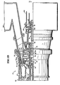
- Figure 4 shows in more detail the manner in which fuel injectors 114 are supported from combustor case 34 and the manner in which combustor air is supplied to combustor 32.
- the fuel injection nozzle 114 illustrated in Figure 4 extends radially through an opening 140 in the combustor case with an integral mounting flange 142 seated on the outer surface of the latter.
- the injector is secured in place as by bolts 144 with a seal 146 being employed to keep compressor discharge air from escaping through the joint between the combustor case and the mounting flange.
- the illustrated combustor 32 is of the annular type.
- the combustor has a circularly sectioned outer liner 148 surrounded by an outer shroud 150 and a concentrically disposed, circularly sectioned inner liner 152 which surrounds an inner shroud 154.
- annular gap between outer combustor liner 148 and inner combustor liner 152 is spanned by an annular, generally U -sectioned, combustor dome 156. Also at this end of the combustor and at stations corresponding to the locations of fuel injection nozzles 114 are combustion air inlet guide members 158 and circular, sliding seal plates 160.
- Fuel injection nozzles 114 are of the air blast type. Fuel supplied to the nozzles is atomized by air discharged from the compressor 12 of gas turbine engine 10 and mixed with an appropriate amount of air; and the fuel-air mixture is then discharged into combustor 32.
- Fuel injection nozzles 114 are component parts of the liquid fuel supply system 108 employed to introduce liquid fuel into the combustor 32 of gas turbine engine 10. As suggested above, and as will be described in detail hereinafter, these same nozzles can also be utilized to instead, or simultaneously, introduce a gaseous fuel such as natural gas or sewer gas into the combustor.
- the illustrated fuel injection nozzle 114 includes an elongate, circularly sectioned stem 162; a nozzle body 164; and shrouds 166 and 168.
- Shroud 166 cooperates with nozzle body 164 at the downstream or discharge end thereof to form an annular discharge passage 170 for liquid fuel.
- the second shroud 168 concentrically surrounds, and cooperates with, nozzle body 164 and shroud 166 to form an annular passage 172 for gaseous fuels.
- shroud 168 supports an array of equiangularly spaced, radially extending, secondary air swirl vanes 174, only two of which are shown.
- Surrounding, and supported by, swirl vanes 174 is a cylindrical, secondary air shroud 176.
- This shroud supports an array of equiangularly spaced, radially extending swirl vanes 178, two of which are shown in Figure 5.
- the fuel injection nozzle stem 168 from which the just-described components are supported is made up of an inner component 180, a heat shield 182 surrounding the latter, and the mounting flange 142 referred to above.
- Longitudinally extending passages (not shown) for liquid fuels, gaseous fuels, and assist air employed to promote atomization at light-off are formed in fuel injection nozzle stem member 180.
- Fuel introduced into the passage for liquid fuels flows through it and then through fuel distribution orifices in the nozzle body (likewise not shown) into the liquid fuel discharge passage 170 between the nozzle body and shroud 166.
- the passage in fuel injection nozzle stem 162 for gas fuels is inclined toward the discharge end of the injection nozzle at the inner end of the passage. There, it communicates with the annular gaseous fuel passage 176 formed between nozzle body 164 and shroud 168.
- Primary air can also be introduced into passage 186 through the inlet 188 thereto at the upstream end of the nozzle body.
- a swirler 190 is mounted in the upstream end of nozzle body 164 to impart a rotational component to primary air introduced into central passage 186.
- liquid fuels, gaseous fuels, and assist air are introduced into the passages in fuel injection nozzles stem 162 through fittings 192, 194, and 196, respectively.
- fittings 192, 194, and 196 are not part of my invention. These details will accordingly not be taken up herein.
- liquid fuel introduced into fuel injection nozzle 114 flows into the discharge passage 170 between nozzle body 164 and shroud 166 as discussed above.
- the discharge end 200 of the nozzle body is configured to match. Consequently, the liquid fuel is discharged from the fuel injection nozzle in the form of a thin film toward the axial centerline 204 of that longitudinally extending part of the fuel injection nozzle.
- This thin film of liquid fuel is contacted, and atomized, by the high velocity, swirling, primary combustion air discharged from the central air passage 186 through nozzle body 164, the air mixing with the fuel as atomization proceeds.
- Secondary combustion air flows from air inlet guide member 158 through swirl vanes 174 which impart a rotational component to the secondary air.
- Shroud 176 as an inwardly inclined, annular lip 206. Consequently, the swirling secondary combustion air is directed inwardly and into contact with the mixing, atomizing fuel and primary combustion air. This promotes the atomization of the liquid fuel and the uniform distribution of the atomized fuel in the combustion mixture.
- the resulting fuel-air mixture then expands radially and is contacted by the rotating air exiting from the passage 198 in which swirl vanes 178 are located. This produces the air-fuel (or stoichiometric) ratio needed for efficient combustion. It also generates the fuel-air mixture swirl angle and the distribution and recirculation of the mixture in combustor 32 required for efficient combustion.
- the primary and secondary combustion air as well as that formed into a swirling annulus by vanes 198 is taken from the discharge side of compressor 12. More specifically, air discharged from the compressor flows through diverging diffuser 28 and is dumped into the forward part of plenum 30, decreasing the flow velocity of the air. From plenum 30 the air flows through air inlet guides 158 and, also, into heat transfer relationship with the outer and inner liners 148 and 152 of combustor 32 to cool those combustor components.
- the details of the compressor-combustor interface which are not part of the present,invention, may be found in U.S.- A - 4,167,907
- the compressor discharge pressure may not be high enough at light-off to guarantee proper atomization of liquid fuel via the mechanisms just described; and, as was also discussed, assist air may be introduced into fuel injection nozzle 114 via fitting 196 for that purpose.
- assist air may be introduced into fuel injection nozzle 114 via fitting 196 for that purpose.
- injectors 114 on a gaseous fuel is comparable to the abovedescribed operation on liquid fuel.
- the fuel is discharged from injection nozzle 114 through radially inwardly directed, equiangularly spaced ports 208 at the downstream end of nozzle 114 with a momentum which allows the gas to mix with the swirling primary and secondary combustion air streams without impinging on the lip of shroud 166. This is important as impingement on that lip or other components of the nozzle could create flow disturbances and consequent degradation in the efficiency of the combustion process.
- the mixture formed by the contact between the fuel and the primary and secondary combustion air streams then, as in the case of the liquid fuel-air mixture, expands radially outward into contact with the swirling air discharged through swirl vanes 186. Thereafter, as in the case of the liquid fuel and as it reaches the combustion zone in combustor 32, a mixture with the correct ratio of fuel and with the swirl angle, distribution, and recirculation needed for efficient combustion is formed.
- water can be introduced into combustor 32 by.way of the assist air passage 184 and primary air passage 186 in fuel injection nozzles 114 to reduce the nitrogen oxides emitted by engine 10.
- Compressor discharge air introduced into injection nozzle 114 and caused to rotate by swirler 190 forces the water leaving port or passage 184 into a film on the wall 210 of primary combustion air passage 186 due to centrifical force.
- This film flows off the discharge end 202 of that part of nozzle component 164 in which the primary combustion air passage is formed and mixes with the sheet of fuel discharged from the slot 212 at the downstream or discharge end of liquid fuel supply passage 170.
- the swirling primary combustion air along with that discharged from swirl vanes 174, atomizes the water, as well as the liquid fuel, forming a homogeneous mixture of the two liquids.
- one important advantage of this novel technique for introducing water into a combustion zone to suppress NO formation is that an even and uniform distribution of the water is obtained. Furthermore, in contrast to heretofore proposed systems, high water injection pressures are not required as atomization and mixing are instead achieved by the swirling air discharged through swirlers 174 and 178.
- a related advantage, of considerable importance, is that efficient atomization and uniform mixing of the water, fuel, and combustion air is obtained even at low water to fuel flow ratios.
- system 214 includes a compressor 216 for supplying atomization assist air to fuel injection nozzles 114 during the light-off of gas turbine engine 10 via lines 218 and 220 and a pump 222 for supplying water to the fuel injection nozzles via lines 224 and 220 during operation of the gas turbine engine thereafter.
- valves 226 and 228 are located in air and water supply lines 226 and 228, respectively. During light-off, valve 226 is opened and valve 228 closed, allowing atomization assist air to flow to injectors 114. After light-off, valve 226 is closed, valve 228 opened, and water pumped to the injectors for the purposes discussed above.
- Check valves 230 and 232 are also incorporated in air assist and water supply lines 218 and 224, respectively. These keep water from flowing to compressor 216 when water injection is being employed and air from flowing to pump 222 when assist air is being supplied to the gas turbine engine.
- orifices are preferably installed in the air assist/coolant pigtails so that the coolant will be uniformly distributed along the several fuel injection nozzles 114.
- 0.052 inch diameter orifices were employed.
- Orifices with larger openings, for example 0.056 inch, are also contemplated.
- the pressure on the atomization assist air required for good atomization of the fuel during light-off can be significantly reduced.
- larger orifices may allow a wider variance in the mass flow rate of the coolant to the different injectors to develop, especially at the lower coolant flow rates. This might prove undesirable because a variance in flow rates could result in higher NO emissions.
Landscapes
- Engineering & Computer Science (AREA)
- Chemical & Material Sciences (AREA)
- Combustion & Propulsion (AREA)
- Mechanical Engineering (AREA)
- General Engineering & Computer Science (AREA)
Abstract
Description
- The present invention relates to methods of an and combustion apparatus for reducing the amission of nitrogen oxides, and more particularly to gas turbine engines.
- The oxides of nitrogen (NOX) are harmful atmospheric pollutants, and limitations on the amounts of those substances that can be legally discharged into the atmosphere have and are being curtailed on national, state, and local levels. While this legislation was initially directed toward atmospheric pollution by emissions from automobile engines, it has since and is now being extended to other areas such as stationary internal combustion engines; a category which includes gas turbine engines of the industrial type.
- In internal combustion engines, nitrogen oxides are formed by the reaction between nitrogen and oxygen in the combustion air (thermal NOx) and by the oxidation of fuelbond nitrogen (fuel NOx). This invention is principally concerned with inhibiting the formation of thermal NOx which is typically dominant.
- The formation of thermal NOx involves chemical reactions that are highly temperature dependent, doubling in rate for every 20°C increase in flame temperature at temperatures above 1800°C. Consequently, the rate .of thermal NO formation can be greatly reduced by even small decreases in flame or combustion temperature.
- This temperature reduction can be achieved by introducing a liquid coolant into the primary cumbustion zone of the combustor. This reduces the flame temperature by evaporation of the coolant and because the coolant raises the average specific heat of the combustion mixture.
- Water is one suitable coolant although others are available as is noted in U.S.-A-3,826,080. Deionized water or other water of high quality is preferably employed because minerals dissolved or entrained in the water could damage the combustor- liner or turbine components of the engine. For water, coolant to fuel mass flow ratios of 0.6 to 1.9 are employed.
- The injection of water into a combustion zone is not by itself claimed to be novel; that has theretofore been done by a variety of techniques for several different purposes as evidenced by US-A-38 26 080 identified above, by US-A-2,402,826, US-A-2,509,648, US-A-2,642,852, US-A-3,224,195, US-A-3,749,318, US-A-3,809,523, US-A-3,814,567, US-A-3,921,389, US-A-3,991,559, US-A-4,084,934, US-A-4,089,639, US-A-4,110,973, US-A-4,114,566, US-A-4,160,362, US-A-4,191,134, and US-A-4,214,435.
- According to the present invention a method of reducing the emission of nitrogen oxides generated by burning a liquid fuel in a combustor comprises separately introducing a liquid coolant and the liquid fuel into the combustor and contacting the coolant and the fuel with.a swirling stream of air to atomize the coolant and fuel and to form a combustible fuel-air mixture having.coolant uniformly distributed therein prior to the combustion of the fuel.
- Preferably the water or other coolant and the fuel are introduced into the'combustor separately with the water being supplied in the form of a film surrounded by the liquid fuel. This promotes uniform mixing of the water and fuel and, as a result, a uniform distribution of the water in the combustor's primary combustion zone. This is important because it inhibits the formation of local hot spots which is undesirable because the rate of thermal NO formation is so highly temperature dependent.
- The benefits of the just discussed technique of fuel injection are particularly noticeable when low ratios of coolant to fuel are used.
- Introduction of the coolant into the combustor of a gas turbine engine in the manner just described can be effected by supplying it through the fuel injection nozzle or nozzles typically employed in gas turbine engines. In this case compressor discharge air, first flowed past a swirler, can be used to form the coolant into the wanted film. Swirled compressor discharge air is also used to mix the coolant and fuel as they are discharged from the fuel injection nozzles and to atomize the fuel and coolant mixture as it enters the primary combustion zone.
- This novel method of supplying the coolant to the combutor has the advantages discussed above; it also makes unnecessary the high coolant injection pressures common in heretofore proposed coolant injection systems.
- The invention also includes combustion apparatus comprising a combustor in which liquid fuel can be burned, and means for reducing the emission of nitrogen oxides from the combustor, said means comprising means for separately introducing a liquid coolant and the liquid fuel into the combustor; means for there mixing the coolant with the fuel; means for atomizing the fuel and coolant; and means for forming a uniform mixture of fuel, coolant, and combustion air as the mixture enters the combustor.
- One preferred type of fuel injection nozzle through which the liquid fuel and coolant are introduced has provision for introducing air into its primary combustion air passage from an accessory compressor during start-up to promote the atomization of the fuel. The NO emission reducing coolant can be introduced through this same passage, thereby eliminating the complexity common to other coolant injection systems.
- The preferred form of fuel injection nozzle just discussed may also have a dual fuel capability. This permits, for example, a gas turbine engine to be operated on either a liquid fuel or on a gas fuel or on both types of fuel at the same time.
- An advantage of introducing coolant into gas turbine engine combustors in the manner discussed above is that the decrease in combustor efficiency attributable to the injection of the coolant is minimal. For example, in one series of tests involving a 10,000 shaft horsepower industrial gas turbine engine operated at full 3/4, 1/2, 1/4, and zero loads on DF-2 diesel fuel with water/fuel mass flows ratios ranging from 0 to 1.8, the decrease in combustor efficiency attributable to the injection of water never exceeded one percent except at the relatively unimportant no-load condition (this also means that carbon monoxide and unburned hydrocarbon emissions were low as they are proportional to combustion efficiency). At the same time, reductions in NO emissions of up to 85 percent were obtained.
- The gas turbine referred to above has 21 fuel injection nozzles spaced evenly in a vertically oriented, annular or circular array. The height difference between the air assist and coolant lines or pigtails leading to the upper and lower fuel injection nozzles can produce a considerable difference between the pressure on the coolant flowing to the upper and lower nozzles. As a consequence, at low coolant flow rates, there can be a highly uneven distribution of coolant to the injection nozzles with more coolant flowing to the lower nozzles that to the upper ones. This leads to an uneven distribution of coolant in the combustor's primary combustion zone which is disadvantageous for the reasons discussed above. However, this problem can be solved by installing orifices and/or the use of a manifold system of the type shown in Figure 2 in the pigtails. These reduce the difference in coolant flow to the upper and lower injection nozzles, by increasing the coolant inlet pressure, because mass flow is proportional to


- The manifold system used to supply liquid fuel to the fuel injection nozzles of the gas turbine engines in which NO emissions are reduced in accord with the principles of the present invention enhances the efficiency of the coolant used to suppress thermal NOx formation.
- One example of a gas turbine engine having combustion apparatus according to the present invention will now be described with reference to the accompanying drawings in which:-
- Figures lA and 1B, taken together, constitute a partly sectioned side view of a gas turbine engine;
- Figure 2 shows, schematically, the combustor of the gas turbine engine and, in more detail, certain components of the fuel supply system employed in supplying liquid fuel to the combustor;
- Figure 3 is a fragmentary view of the gas turbine engine of Figure 1 which includes the engine's combustor; manifolds for supplying gas and liquid fuels, atomization assist air, and NOx suppressing coolant to the compressor; and the lines or pigtails leading from the manifolds to the engine's fuel injection nozzles;
- Figure 4 is a fragment of Figure lB to a larger scale showing the upstream or dome end of the gas turbine engine combustor and one of several fuel injection nozzles incorporated in a system for supplying fuel to the engine which includes components that are part of a coolant injection system embodying the principles of my invention;
- Figure 5 is a fragmentary section through certain components of the fuel supply system taken substantially along line 6-6 of Figure 4;
- Figure 6 is a longitudinal section through the fuel injection nozzle shown in Figure 2;
- Figure 7 is a similar section through the inlet end of the nozzle; it was taken at right angles to the section identified as Figure 5; and
- Figure 8 is a schematic of systems used to supply coolant and start-up assist air to the fuel injection nozzles.
-
Engine 10 includes a fifteen-stageaxial flow compressor 12 with a radial-axial inlet 14. Inlet guide vanes 16 and stators 18 of the compressor are supported fromcompressor housing 20 with the guide vanes and the stators 18-1 through 18-5 of the first five stages being pivotally mounted so that they can be adjusted to control the flow of air through the compressor. - The fifteen-stage rotor 22 of
compressor 12 is composed ofdiscs 24 withvanes 26 fixed thereto. The discs are joined as by electron beam welding into a single unit. -
Compressor housing 20 is split longitudinally on a vertical plane through the axial centerline of the housing into twosections 20a (only one of which is shown). This accommodates installation of the compressor rotor and facilitates access to the rotor blades, guide vanes, and stators for inspection, cleaning, and replacement. - The high pressure air discharged from
compressor 12 flows through an annular, divergingdiffuser 28 into an enlargedplenum 30 and from the latter to anannular combustor 32 housed in acase 34. - The hot gasses generated in
combustor 32 are discharged into anozzle case 42 supported in an annular turbine housing 44. The hot gases are expanded first through a two-stagegas producer turbine 46 and then through atwostage power turbine 48. -
Gas producer turbine 46 has internally cooled, first andsecond stage nozzles stage rotor 54. - The
first stage 56 of gasproducer turbine rotor 54 includes adisc 58 to which internally cooled, radially extendingblades 60 are fixed. Thesecond stage 62 includes a disc 64 with uncooled, radially extendingblades 66 mounted on its periphery. - The two stages of gas
producer turbine rotor 54 are bolted to each other and, in cantilever fashion, to the rear end of a forwardly extendingshaft 68. Shaft 68 is keyed torear compressor hub 70 which is bolted to compressor rotor 22, thereby drive-connectinggas producer turbine 46 to the compressor rotor. - The compressor rotor and gas producer turbine are rotatably supported by a thrust bearing 72 engaged with a
front compressor hub 74 drive-connected to anaccessory drive 76 and bytapered land bearings -
Power turbine 48 includes first andsecond stage nozzles nozzle case 42 and arotor 88 having a firstbladed stage 90 and a secondbladed stage 92 bolted together for concomitant rotation. Neither the nozzles nor the rotor are cooled. -
Rotor 88 is bolted to ashaft assembly 94 rotatably supported bytapered land bearings coupling 102 to anoutput shaft assembly 104 which is the input for a generator, booster compressor, mechanical drive, or other driven unit. - Another major component of
turbine engine 10 is anexhaust duct 106 for the gases discharged from the power turbine. - For the most part, the details of the gas turbine engine components discussed above are not relevant to the practice of the present invention. Therefore, they will be described only as necessary to provide a setting for and facilitate an understanding of the latter.
- Referring now primarily to Figures 2 and 3, liquid fuel is supplied to the
combustor 32 ofgas turbine engine 10 by a liquidfuel supply system 108 which includes anupper manifold 110, alower manifold 112, andinjection nozzles 114 supplied with fuel fromupper manifold 110 through fuel lines orpigtails 116 and fromlower manifold 112 through fuel lines orpigtails 118. Fuel is supplied to theupper manifold 110 throughfuel lines lower manifold 112 through afuel line 124 extending between that manifold andfuel supply line 122. Acheck valve 126 is incorporated infuel line 124 for purposes that will become apparent hereinafter. -
Fuel supply system 108 also includes afuel return line 128 connected between lower manifold l12 andfuel line 122. Asecond check valve 130 is incorporated in the fuel return line. - Particularly under the low fuel pressure conditions existing at light-off, the hydraulic head H across the fuel supply system would result in the fuel reaching those
fuel injection nozzles 114 toward the bottom ofcombustor 32 much more rapidly than the uppermost injection nozzles if a simple ring type manifold were employed to supply fuel to the injection nozzles. This inequality of flow distribution is significantly reduced in the illustrated liquidfuel supply system 108 by the flow equalizing arrangement composed offuel line 124 andcheck valve 126. Specifically,check valve 126 is set to open when the pressure infuel line 122 reaches one-half of the hydraulic head H across the system. That reduces the fuel pressure at the bottom oflower manifold 112; and, consequently, the pressure vertically across that manifold (check valve outlet pressure - H/2) more nearly equals the pressure across theupper manifold 110 and its fuel supply 122 (line pressure in 122 - H) than would otherwise be the case. - Also, by thus reducing the effect of the hydraulic head across
fuel supply system 108, the arrangement just described results in a more uniform flow of fuel to the fuel injection nozzles at different elevations during the operation of the engine with which the fuel supply system is associated. This, too results in more efficient combustion and lower emission levels. - The final feature of
fuel supply system 108 alluded to above --fuel return line 128 -- is provided so that fuel can drain fromlower manifold 112 back intofuel lines engine 10 is shut down. Thecheck valve 130 inline 128 is oriented for fuel flow in that direction. - As long as the engine is running and fuel is being supplied to it through
fuel lines line 122 is higher than that inlower manifold 112 by virtue of the pressure drop acrosscheck valve 126; andvalve 130 accordingly remains closed. When the engine is shut down, however, the pressure inlines return line 128. - Referring now to Figure 3, gaseous fuels are supplied to
fuel injection nozzles 114 via acircular manifold 132 which also surrounds and is supported fromcombustor case 34. Lines orpigtails 134 spaced equiangularly therearound connect the manifold to the severalfuel injection nozzles 114. -
Gas turbine engine 10 is also equipped with a circular or annular air assistmanifold 136. Like the gas and liquid fuel manifolds, the air assist manifold surrounds and is supported from the combustor case. That manifold is connected to the severalfuel injection nozzles 114 by an equiangularly spaced array of air supply lines orpigtails 138. - As shown in Figure 2,
combustor 32 has a circular section; and thefuel injection nozzles 114 are spaced around this casing in a circular array at essentially equal intervals with the discharge or downstream ends of the injectors located inside of, and discharging atomized fuel into,combustor 32. - Referring still to the drawing, Figure 4 shows in more detail the manner in which
fuel injectors 114 are supported fromcombustor case 34 and the manner in which combustor air is supplied tocombustor 32. - The
fuel injection nozzle 114 illustrated in Figure 4 extends radially through an opening 140 in the combustor case with anintegral mounting flange 142 seated on the outer surface of the latter. The injector is secured in place as bybolts 144 with aseal 146 being employed to keep compressor discharge air from escaping through the joint between the combustor case and the mounting flange. - The illustrated
combustor 32 is of the annular type. The combustor has a circularly sectionedouter liner 148 surrounded by anouter shroud 150 and a concentrically disposed, circularly sectionedinner liner 152 which surrounds aninner shroud 154. - At the upstream end of
combustor 32, the annular gap betweenouter combustor liner 148 andinner combustor liner 152 is spanned by an annular, generally U-sectioned,combustor dome 156. Also at this end of the combustor and at stations corresponding to the locations offuel injection nozzles 114 are combustion airinlet guide members 158 and circular, slidingseal plates 160. - The details of the combustor as just described are not part of my present invention, and they will accordingly be alluded to hereinafter only as necessary to facilitate an understanding of that invention.
-
Fuel injection nozzles 114 are of the air blast type. Fuel supplied to the nozzles is atomized by air discharged from thecompressor 12 ofgas turbine engine 10 and mixed with an appropriate amount of air; and the fuel-air mixture is then discharged intocombustor 32. - Referring again to the drawing, Figures 5-7 illustrate, in more detail, one of the
fuel injection nozzles 114 referred to above.Fuel injection nozzles 114 are component parts of the liquidfuel supply system 108 employed to introduce liquid fuel into thecombustor 32 ofgas turbine engine 10. As suggested above, and as will be described in detail hereinafter, these same nozzles can also be utilized to instead, or simultaneously, introduce a gaseous fuel such as natural gas or sewer gas into the combustor. - The illustrated
fuel injection nozzle 114 includes an elongate, circularly sectionedstem 162; anozzle body 164; and shrouds 166 and 168.Shroud 166 cooperates withnozzle body 164 at the downstream or discharge end thereof to form anannular discharge passage 170 for liquid fuel. Thesecond shroud 168 concentrically surrounds, and cooperates with,nozzle body 164 andshroud 166 to form anannular passage 172 for gaseous fuels. - At its forward or discharge end,
shroud 168 supports an array of equiangularly spaced, radially extending, secondaryair swirl vanes 174, only two of which are shown. Surrounding, and supported by,swirl vanes 174 is a cylindrical,secondary air shroud 176. This shroud supports an array of equiangularly spaced, radially extendingswirl vanes 178, two of which are shown in Figure 5. - The fuel injection nozzle stem 168 from which the just-described components are supported is made up of an
inner component 180, aheat shield 182 surrounding the latter, and the mountingflange 142 referred to above. Longitudinally extending passages (not shown) for liquid fuels, gaseous fuels, and assist air employed to promote atomization at light-off are formed in fuel injectionnozzle stem member 180. Fuel introduced into the passage for liquid fuels flows through it and then through fuel distribution orifices in the nozzle body (likewise not shown) into the liquidfuel discharge passage 170 between the nozzle body andshroud 166. - The passage in fuel
injection nozzle stem 162 for gas fuels is inclined toward the discharge end of the injection nozzle at the inner end of the passage. There, it communicates with the annulargaseous fuel passage 176 formed betweennozzle body 164 andshroud 168. - Assist air introduced into
nozzle stem 162 flows from aninclined passage 184 in the stem into aprimary air passage 186 which extends from end to end ofnozzle body 164 and is concentric with the axial centerline of that component. - Primary air can also be introduced into
passage 186 through theinlet 188 thereto at the upstream end of the nozzle body. Aswirler 190 is mounted in the upstream end ofnozzle body 164 to impart a rotational component to primary air introduced intocentral passage 186. - Referring now primarily to Figure 7, liquid fuels, gaseous fuels, and assist air are introduced into the passages in fuel injection nozzles stem 162 through
fittings injection nozzle stem 162 are not part of my invention. These details will accordingly not be taken up herein. - As is best shown in Figure 4, that inner, longitudinally extending part of
fuel injection nozzle 114 made up ofnozzle body 164 andshrouds inlet guide member 158 and through slidingseal plate 160, leaving anannular passage 198 between the seal plate and fuel injection nozzlesecondary air shroud 176.Swirl vanes 178 span, and impart a rotational component to, combustion air discharged through this passage intocombustor 32. - Referring now primarily to Figures 4-6, liquid fuel introduced into
fuel injection nozzle 114 flows into thedischarge passage 170 betweennozzle body 164 andshroud 166 as discussed above. Thedischarge end 200 of the nozzle body is configured to match. Consequently, the liquid fuel is discharged from the fuel injection nozzle in the form of a thin film toward theaxial centerline 204 of that longitudinally extending part of the fuel injection nozzle. This thin film of liquid fuel is contacted, and atomized, by the high velocity, swirling, primary combustion air discharged from thecentral air passage 186 throughnozzle body 164, the air mixing with the fuel as atomization proceeds. - Secondary combustion air flows from air
inlet guide member 158 throughswirl vanes 174 which impart a rotational component to the secondary air.Shroud 176 as an inwardly inclined,annular lip 206. Consequently, the swirling secondary combustion air is directed inwardly and into contact with the mixing, atomizing fuel and primary combustion air. This promotes the atomization of the liquid fuel and the uniform distribution of the atomized fuel in the combustion mixture. - The resulting fuel-air mixture then expands radially and is contacted by the rotating air exiting from the
passage 198 in which swirlvanes 178 are located. This produces the air-fuel (or stoichiometric) ratio needed for efficient combustion. It also generates the fuel-air mixture swirl angle and the distribution and recirculation of the mixture incombustor 32 required for efficient combustion. - As indicated above, the primary and secondary combustion air as well as that formed into a swirling annulus by
vanes 198 is taken from the discharge side ofcompressor 12. More specifically, air discharged from the compressor flows through divergingdiffuser 28 and is dumped into the forward part ofplenum 30, decreasing the flow velocity of the air. Fromplenum 30 the air flows through air inlet guides 158 and, also, into heat transfer relationship with the outer andinner liners combustor 32 to cool those combustor components. The details of the compressor-combustor interface, which are not part of the present,invention, may be found in U.S.- A - 4,167,907 - As discussed above, the compressor discharge pressure may not be high enough at light-off to guarantee proper atomization of liquid fuel via the mechanisms just described; and, as was also discussed, assist air may be introduced into
fuel injection nozzle 114 via fitting 196 for that purpose. One exemplary system for accomplishing this is disclosed in our copending application (Representatives Reference 90/2018/02) filed concurrently herewith. - Referring again to Figures 3-7, the operation of
injectors 114 on a gaseous fuel is comparable to the abovedescribed operation on liquid fuel. In the case of the gaseous fuel, however, the fuel is discharged frominjection nozzle 114 through radially inwardly directed, equiangularly spacedports 208 at the downstream end ofnozzle 114 with a momentum which allows the gas to mix with the swirling primary and secondary combustion air streams without impinging on the lip ofshroud 166. This is important as impingement on that lip or other components of the nozzle could create flow disturbances and consequent degradation in the efficiency of the combustion process. - The mixture formed by the contact between the fuel and the primary and secondary combustion air streams then, as in the case of the liquid fuel-air mixture, expands radially outward into contact with the swirling air discharged through
swirl vanes 186. Thereafter, as in the case of the liquid fuel and as it reaches the combustion zone incombustor 32, a mixture with the correct ratio of fuel and with the swirl angle, distribution, and recirculation needed for efficient combustion is formed. - Referring now in particular to Figures 3-8, as referred to= above that water can be introduced into
combustor 32 by.way of theassist air passage 184 andprimary air passage 186 infuel injection nozzles 114 to reduce the nitrogen oxides emitted byengine 10. Compressor discharge air introduced intoinjection nozzle 114 and caused to rotate byswirler 190 forces the water leaving port orpassage 184 into a film on thewall 210 of primarycombustion air passage 186 due to centrifical force. - This film flows off the
discharge end 202 of that part ofnozzle component 164 in which the primary combustion air passage is formed and mixes with the sheet of fuel discharged from theslot 212 at the downstream or discharge end of liquidfuel supply passage 170. - The swirling primary combustion air, along with that discharged from
swirl vanes 174, atomizes the water, as well as the liquid fuel, forming a homogeneous mixture of the two liquids. - As suggested above, one important advantage of this novel technique for introducing water into a combustion zone to suppress NO formation is that an even and uniform distribution of the water is obtained. Furthermore, in contrast to heretofore proposed systems, high water injection pressures are not required as atomization and mixing are instead achieved by the swirling air discharged through
swirlers - One exemplary system for supplying water and atomization assist air during light-off to
fuel injection nozzles 114 is illustrated schematically in Figure 8 and identified byreference character 214. In addition to the manifold 136 andpigtails 138 discussed above,system 214 includes acompressor 216 for supplying atomization assist air tofuel injection nozzles 114 during the light-off ofgas turbine engine 10 vialines pump 222 for supplying water to the fuel injection nozzles vialines -
Conventional solenoid valves water supply lines valve 226 is opened andvalve 228 closed, allowing atomization assist air to flow toinjectors 114. After light-off,valve 226 is closed,valve 228 opened, and water pumped to the injectors for the purposes discussed above. - Check
valves water supply lines compressor 216 when water injection is being employed and air from flowing to pump 222 when assist air is being supplied to the gas turbine engine. - The efficacy of my novel technique for reducing the nitrogen oxides generated in a combustion process was demonstrated by tests in which a gas turbine engine of the type discussed above and identified by
reference character 10 in the drawings was run as discussed above at a constant power turbine inlet temperature and over the range of operating conditions varying from no-load to full load and at a still higher load level (1935°F TRIT) that might be encountered under standby applications of the engine, for example. The water to fuel mass flow ratios employed at the various load conditions and the reductions in NO emissions that were obtained are tabulated along with related, relevant data in the following tables:


- As will be apparent from the foregoing tables, reduction in NO emissions of up to 82 percent were obtained in the tests. On the other hand, the decrease in combustor efficiency was never more than about one percent under any of the rest conditions except at no-load. The test at that condition, which is obviously not as significant as those at load conditions from a practical viewpoint, was aborted because a somewhat larger decrease in combustor efficiency (1.56) was experienced.
- It was pointed out above that orifices are preferably installed in the air assist/coolant pigtails so that the coolant will be uniformly distributed along the several
fuel injection nozzles 114. In the test described above, 0.052 inch diameter orifices were employed. Orifices with larger openings, for example 0.056 inch, are also contemplated. - By increasing the size of the opening, the pressure on the atomization assist air required for good atomization of the fuel during light-off can be significantly reduced. On the other hand, larger orifices may allow a wider variance in the mass flow rate of the coolant to the different injectors to develop, especially at the lower coolant flow rates. This might prove undesirable because a variance in flow rates could result in higher NO emissions.
- The principles of the invention were developed above specifically with reference to their application to gas turbine engines, and more specifically, to engines of that character equipped with a dual fuel supply system. It is to be understood, however, that the invention is of much broader utility. Specifically, the invention is readily adaptable to a wide range or air blast fuel injection nozzles and, generally, to the reduction of NO emissions in other settings, not just those involving gas turbine engines. Consequently, to the extent that specific applications of my invention are not expressly ruled out by the appended claims, they are fully intended to be covered in them.
Claims (21)
Applications Claiming Priority (2)
| Application Number | Priority Date | Filing Date | Title |
|---|---|---|---|
| US288510 | 1981-07-30 | ||
| US06/288,510 US4483137A (en) | 1981-07-30 | 1981-07-30 | Gas turbine engine construction and operation |
Publications (2)
| Publication Number | Publication Date |
|---|---|
| EP0071419A1 true EP0071419A1 (en) | 1983-02-09 |
| EP0071419B1 EP0071419B1 (en) | 1985-09-11 |
Family
ID=23107429
Family Applications (1)
| Application Number | Title | Priority Date | Filing Date |
|---|---|---|---|
| EP82303878A Expired EP0071419B1 (en) | 1981-07-30 | 1982-07-22 | Combustion apparatus with reduced nitrogen oxide emission |
Country Status (5)
| Country | Link |
|---|---|
| US (1) | US4483137A (en) |
| EP (1) | EP0071419B1 (en) |
| JP (1) | JPS5822810A (en) |
| CA (1) | CA1194322A (en) |
| DE (1) | DE3266197D1 (en) |
Cited By (4)
| Publication number | Priority date | Publication date | Assignee | Title |
|---|---|---|---|---|
| WO1994029647A1 (en) * | 1993-06-10 | 1994-12-22 | Solar Turbines Incorporated | Dual fuel injector nozzel for use with a gas turbine engine |
| DE19548739A1 (en) * | 1995-12-23 | 1997-06-26 | Asea Brown Boveri | Process for fuel distribution in axially symmetric burner chamber |
| EP1905985A3 (en) * | 2006-09-18 | 2013-10-30 | Pratt & Whitney Canada Corp. | Internal fuel manifold having temperature reduction feature |
| EP3483504A1 (en) * | 2017-11-09 | 2019-05-15 | Doosan Heavy Industries & Construction Co., Ltd | Combustor and gas turbine including the same |
Families Citing this family (40)
| Publication number | Priority date | Publication date | Assignee | Title |
|---|---|---|---|---|
| US5146741A (en) * | 1990-09-14 | 1992-09-15 | Solar Turbines Incorporated | Gaseous fuel injector |
| US5129582A (en) * | 1990-12-26 | 1992-07-14 | General Turbine Systems, Inc. | Turbine injector device and method |
| US5259184A (en) * | 1992-03-30 | 1993-11-09 | General Electric Company | Dry low NOx single stage dual mode combustor construction for a gas turbine |
| US5288021A (en) * | 1992-08-03 | 1994-02-22 | Solar Turbines Incorporated | Injection nozzle tip cooling |
| US5303554A (en) * | 1992-11-27 | 1994-04-19 | Solar Turbines Incorporated | Low NOx injector with central air swirling and angled fuel inlets |
| US5426933A (en) * | 1994-01-11 | 1995-06-27 | Solar Turbines Incorporated | Dual feed injection nozzle with water injection |
| JP2877098B2 (en) | 1995-12-28 | 1999-03-31 | 株式会社日立製作所 | Gas turbines, combined cycle plants and compressors |
| EP1406047A4 (en) * | 2001-07-10 | 2010-04-07 | Mitsubishi Heavy Ind Ltd | Premixing nozzle, burner and gas turbine |
| US8631657B2 (en) | 2003-01-22 | 2014-01-21 | Vast Power Portfolio, Llc | Thermodynamic cycles with thermal diluent |
| JP2006523294A (en) * | 2003-01-22 | 2006-10-12 | ヴァスト・パワー・システムズ・インコーポレーテッド | Reactor |
| US20050056313A1 (en) * | 2003-09-12 | 2005-03-17 | Hagen David L. | Method and apparatus for mixing fluids |
| US20060156733A1 (en) * | 2005-01-14 | 2006-07-20 | Pratt & Whitney Canada Corp. | Integral heater for fuel conveying member |
| US7565807B2 (en) * | 2005-01-18 | 2009-07-28 | Pratt & Whitney Canada Corp. | Heat shield for a fuel manifold and method |
| US20060162338A1 (en) * | 2005-01-21 | 2006-07-27 | Pratt & Whitney Canada Corp. | Evacuation of hot gases accumulated in an inactive gas turbine engine |
| US7530231B2 (en) * | 2005-04-01 | 2009-05-12 | Pratt & Whitney Canada Corp. | Fuel conveying member with heat pipe |
| US7533531B2 (en) * | 2005-04-01 | 2009-05-19 | Pratt & Whitney Canada Corp. | Internal fuel manifold with airblast nozzles |
| US20120266792A1 (en) * | 2006-05-17 | 2012-10-25 | Majed Toqan | Combustion Stabilization Systems |
| US8215949B2 (en) * | 2006-05-17 | 2012-07-10 | Majed Toqan | Combustion stabilization systems |
| US8096130B2 (en) * | 2006-07-20 | 2012-01-17 | Pratt & Whitney Canada Corp. | Fuel conveying member for a gas turbine engine |
| US8353166B2 (en) * | 2006-08-18 | 2013-01-15 | Pratt & Whitney Canada Corp. | Gas turbine combustor and fuel manifold mounting arrangement |
| US7765808B2 (en) * | 2006-08-22 | 2010-08-03 | Pratt & Whitney Canada Corp. | Optimized internal manifold heat shield attachment |
| US8033113B2 (en) * | 2006-08-31 | 2011-10-11 | Pratt & Whitney Canada Corp. | Fuel injection system for a gas turbine engine |
| US20080053096A1 (en) * | 2006-08-31 | 2008-03-06 | Pratt & Whitney Canada Corp. | Fuel injection system and method of assembly |
| US7775047B2 (en) * | 2006-09-22 | 2010-08-17 | Pratt & Whitney Canada Corp. | Heat shield with stress relieving feature |
| US7926286B2 (en) * | 2006-09-26 | 2011-04-19 | Pratt & Whitney Canada Corp. | Heat shield for a fuel manifold |
| US7716933B2 (en) * | 2006-10-04 | 2010-05-18 | Pratt & Whitney Canada Corp. | Multi-channel fuel manifold |
| US8572976B2 (en) * | 2006-10-04 | 2013-11-05 | Pratt & Whitney Canada Corp. | Reduced stress internal manifold heat shield attachment |
| US7856825B2 (en) * | 2007-05-16 | 2010-12-28 | Pratt & Whitney Canada Corp. | Redundant mounting system for an internal fuel manifold |
| US8146365B2 (en) * | 2007-06-14 | 2012-04-03 | Pratt & Whitney Canada Corp. | Fuel nozzle providing shaped fuel spray |
| US8393154B2 (en) * | 2009-02-12 | 2013-03-12 | Pratt & Whitney Canada Corp. | Fuel delivery system with reduced heat transfer to fuel manifold seal |
| US8640974B2 (en) * | 2010-10-25 | 2014-02-04 | General Electric Company | System and method for cooling a nozzle |
| US8919132B2 (en) | 2011-05-18 | 2014-12-30 | Solar Turbines Inc. | Method of operating a gas turbine engine |
| US8893500B2 (en) | 2011-05-18 | 2014-11-25 | Solar Turbines Inc. | Lean direct fuel injector |
| US9182124B2 (en) | 2011-12-15 | 2015-11-10 | Solar Turbines Incorporated | Gas turbine and fuel injector for the same |
| WO2015023863A1 (en) | 2013-08-16 | 2015-02-19 | United Technologies Corporation | Cooled fuel injector system for a gas turbine engine |
| US10731861B2 (en) * | 2013-11-18 | 2020-08-04 | Raytheon Technologies Corporation | Dual fuel nozzle with concentric fuel passages for a gas turbine engine |
| US10309655B2 (en) * | 2014-08-26 | 2019-06-04 | Siemens Energy, Inc. | Cooling system for fuel nozzles within combustor in a turbine engine |
| US20170198635A1 (en) * | 2016-01-07 | 2017-07-13 | General Electric Company | High flow on-line water wash using sprint nozzle |
| US11285571B1 (en) * | 2021-01-25 | 2022-03-29 | Delavan Inc. | Fuel nozzle seal removal tool |
| US11846422B2 (en) * | 2021-08-19 | 2023-12-19 | Collins Engine Nozzles, Inc. | Systems for fuel injectors with fuel air heat exchangers |
Citations (16)
| Publication number | Priority date | Publication date | Assignee | Title |
|---|---|---|---|---|
| FR383966A (en) * | 1907-09-26 | 1908-03-25 | Armand Ferrier | Internal combustion turbine |
| GB577062A (en) * | 1944-10-30 | 1946-05-02 | Dehavilland Aircraft | Improvements in or relating to turbo-compressor propulsive apparatus |
| GB780835A (en) * | 1954-09-21 | 1957-08-07 | Rolls Royce | Improvements relating to combustion equipment for gas-turbine engines and fuel injection means therefor |
| US3623668A (en) * | 1968-03-04 | 1971-11-30 | Gen Electric | Wash manifold |
| FR2095475A5 (en) * | 1970-06-26 | 1972-02-11 | Ex Cell O Corp | |
| US3763650A (en) * | 1971-07-26 | 1973-10-09 | Westinghouse Electric Corp | Gas turbine temperature profiling structure |
| US3774851A (en) * | 1972-11-15 | 1973-11-27 | Parker Hannifin Corp | Fuel head compensating valve for fuel injection nozzle |
| US3826080A (en) * | 1973-03-15 | 1974-07-30 | Westinghouse Electric Corp | System for reducing nitrogen-oxygen compound in the exhaust of a gas turbine |
| FR2337255A1 (en) * | 1975-12-29 | 1977-07-29 | Garrett Corp | GAS TURBINE IMPROVEMENTS |
| GB2003552A (en) * | 1977-08-31 | 1979-03-14 | Parker Hannifin Corp | Fuel nozzle |
| GB2035540A (en) * | 1978-11-23 | 1980-06-18 | Rolls Royce | A gas turbine engine fuel injector |
| GB2041085A (en) * | 1978-12-20 | 1980-09-03 | Lucas Industries Ltd | Fuel supply apparatus for gas turbine engine |
| US4242076A (en) * | 1978-01-03 | 1980-12-30 | Rawyler Ehrat Ernst | Process of combustion |
| GB2050592A (en) * | 1979-06-06 | 1981-01-07 | Rolls Royce | Gas turbine |
| GB2055186A (en) * | 1979-08-01 | 1981-02-25 | Rolls Royce | Gas turbine engine dual fuel injector |
| GB2083904A (en) * | 1980-09-16 | 1982-03-31 | Rolls Royce | Improvements in or relating to gas turbine engine dual fuel burners |
Family Cites Families (5)
| Publication number | Priority date | Publication date | Assignee | Title |
|---|---|---|---|---|
| US3980233A (en) * | 1974-10-07 | 1976-09-14 | Parker-Hannifin Corporation | Air-atomizing fuel nozzle |
| GB1547770A (en) * | 1975-09-06 | 1979-06-27 | Rolls Royce | Gas turbine engine fuel injectocorsvk |
| GB1597968A (en) * | 1977-06-10 | 1981-09-16 | Rolls Royce | Fuel burners for gas turbine engines |
| JPS5490410A (en) * | 1977-12-28 | 1979-07-18 | Mitsubishi Heavy Ind Ltd | Combustor for gas turbine |
| US4327547A (en) * | 1978-11-23 | 1982-05-04 | Rolls-Royce Limited | Fuel injectors |
-
1981
- 1981-07-30 US US06/288,510 patent/US4483137A/en not_active Expired - Lifetime
-
1982
- 1982-05-28 CA CA000404021A patent/CA1194322A/en not_active Expired
- 1982-06-30 JP JP57113831A patent/JPS5822810A/en active Granted
- 1982-07-22 EP EP82303878A patent/EP0071419B1/en not_active Expired
- 1982-07-22 DE DE8282303878T patent/DE3266197D1/en not_active Expired
Patent Citations (16)
| Publication number | Priority date | Publication date | Assignee | Title |
|---|---|---|---|---|
| FR383966A (en) * | 1907-09-26 | 1908-03-25 | Armand Ferrier | Internal combustion turbine |
| GB577062A (en) * | 1944-10-30 | 1946-05-02 | Dehavilland Aircraft | Improvements in or relating to turbo-compressor propulsive apparatus |
| GB780835A (en) * | 1954-09-21 | 1957-08-07 | Rolls Royce | Improvements relating to combustion equipment for gas-turbine engines and fuel injection means therefor |
| US3623668A (en) * | 1968-03-04 | 1971-11-30 | Gen Electric | Wash manifold |
| FR2095475A5 (en) * | 1970-06-26 | 1972-02-11 | Ex Cell O Corp | |
| US3763650A (en) * | 1971-07-26 | 1973-10-09 | Westinghouse Electric Corp | Gas turbine temperature profiling structure |
| US3774851A (en) * | 1972-11-15 | 1973-11-27 | Parker Hannifin Corp | Fuel head compensating valve for fuel injection nozzle |
| US3826080A (en) * | 1973-03-15 | 1974-07-30 | Westinghouse Electric Corp | System for reducing nitrogen-oxygen compound in the exhaust of a gas turbine |
| FR2337255A1 (en) * | 1975-12-29 | 1977-07-29 | Garrett Corp | GAS TURBINE IMPROVEMENTS |
| GB2003552A (en) * | 1977-08-31 | 1979-03-14 | Parker Hannifin Corp | Fuel nozzle |
| US4242076A (en) * | 1978-01-03 | 1980-12-30 | Rawyler Ehrat Ernst | Process of combustion |
| GB2035540A (en) * | 1978-11-23 | 1980-06-18 | Rolls Royce | A gas turbine engine fuel injector |
| GB2041085A (en) * | 1978-12-20 | 1980-09-03 | Lucas Industries Ltd | Fuel supply apparatus for gas turbine engine |
| GB2050592A (en) * | 1979-06-06 | 1981-01-07 | Rolls Royce | Gas turbine |
| GB2055186A (en) * | 1979-08-01 | 1981-02-25 | Rolls Royce | Gas turbine engine dual fuel injector |
| GB2083904A (en) * | 1980-09-16 | 1982-03-31 | Rolls Royce | Improvements in or relating to gas turbine engine dual fuel burners |
Cited By (6)
| Publication number | Priority date | Publication date | Assignee | Title |
|---|---|---|---|---|
| WO1994029647A1 (en) * | 1993-06-10 | 1994-12-22 | Solar Turbines Incorporated | Dual fuel injector nozzel for use with a gas turbine engine |
| DE19548739A1 (en) * | 1995-12-23 | 1997-06-26 | Asea Brown Boveri | Process for fuel distribution in axially symmetric burner chamber |
| DE19548739C2 (en) * | 1995-12-23 | 2003-10-09 | Alstom | Process for fuel distribution in an axially mounted combustion chamber |
| EP1905985A3 (en) * | 2006-09-18 | 2013-10-30 | Pratt & Whitney Canada Corp. | Internal fuel manifold having temperature reduction feature |
| EP3483504A1 (en) * | 2017-11-09 | 2019-05-15 | Doosan Heavy Industries & Construction Co., Ltd | Combustor and gas turbine including the same |
| US11060728B2 (en) | 2017-11-09 | 2021-07-13 | Doosan Heavy Industries & Construction Co., Ltd. | Combustor and gas turbine including the same |
Also Published As
| Publication number | Publication date |
|---|---|
| JPS5822810A (en) | 1983-02-10 |
| DE3266197D1 (en) | 1985-10-17 |
| US4483137A (en) | 1984-11-20 |
| EP0071419B1 (en) | 1985-09-11 |
| CA1194322A (en) | 1985-10-01 |
| JPH0325683B2 (en) | 1991-04-08 |
Similar Documents
| Publication | Publication Date | Title |
|---|---|---|
| EP0071419B1 (en) | Combustion apparatus with reduced nitrogen oxide emission | |
| US3982392A (en) | Combustion apparatus | |
| US4112676A (en) | Hybrid combustor with staged injection of pre-mixed fuel | |
| US5218824A (en) | Low emission combustion nozzle for use with a gas turbine engine | |
| JP4658471B2 (en) | Method and apparatus for reducing combustor emissions in a gas turbine engine | |
| US3958413A (en) | Combustion method and apparatus | |
| US5850732A (en) | Low emissions combustion system for a gas turbine engine | |
| US6192688B1 (en) | Premixing dry low nox emissions combustor with lean direct injection of gas fule | |
| US6374594B1 (en) | Silo/can-annular low emissions combustor | |
| US5974780A (en) | Method for reducing the production of NOX in a gas turbine | |
| US3826080A (en) | System for reducing nitrogen-oxygen compound in the exhaust of a gas turbine | |
| EP0620906B1 (en) | Low emission combustion system for a gas turbine engine | |
| US20060016195A1 (en) | Bypass and injection method and apparatus for gas turbines | |
| US6449956B1 (en) | Bypass air injection method and apparatus for gas turbines | |
| US5365738A (en) | Low emission combustion nozzle for use with a gas turbine engine | |
| CN1601181A (en) | Method and apparatus for reducing gas turbine engine emissions | |
| US20010049932A1 (en) | Premixing dry low NOx emissions combustor with lean direct injection of gas fuel | |
| US5372008A (en) | Lean premix combustor system | |
| US5303554A (en) | Low NOx injector with central air swirling and angled fuel inlets | |
| EP0071420B1 (en) | Dual fuel injection nozzles | |
| US5321947A (en) | Lean premix combustion system having reduced combustion pressure oscillation | |
| GB2035540A (en) | A gas turbine engine fuel injector | |
| CA2099275A1 (en) | Low emission combustion system for a gas turbine engine | |
| WO1993022601A1 (en) | Premix liquid and gaseous combustion nozzle for use with a gas turbine engine | |
| JP3117995B2 (en) | Low emission combustion system for gas turbine engine |
Legal Events
| Date | Code | Title | Description |
|---|---|---|---|
| PUAI | Public reference made under article 153(3) epc to a published international application that has entered the european phase |
Free format text: ORIGINAL CODE: 0009012 |
|
| AK | Designated contracting states |
Designated state(s): CH DE FR GB IT LI |
|
| 17P | Request for examination filed |
Effective date: 19830722 |
|
| ITF | It: translation for a ep patent filed | ||
| GRAA | (expected) grant |
Free format text: ORIGINAL CODE: 0009210 |
|
| AK | Designated contracting states |
Designated state(s): CH DE FR GB IT LI |
|
| REF | Corresponds to: |
Ref document number: 3266197 Country of ref document: DE Date of ref document: 19851017 |
|
| ET | Fr: translation filed | ||
| PLBE | No opposition filed within time limit |
Free format text: ORIGINAL CODE: 0009261 |
|
| STAA | Information on the status of an ep patent application or granted ep patent |
Free format text: STATUS: NO OPPOSITION FILED WITHIN TIME LIMIT |
|
| 26N | No opposition filed | ||
| ITTA | It: last paid annual fee | ||
| PGFP | Annual fee paid to national office [announced via postgrant information from national office to epo] |
Ref country code: FR Payment date: 19950525 Year of fee payment: 14 |
|
| PGFP | Annual fee paid to national office [announced via postgrant information from national office to epo] |
Ref country code: DE Payment date: 19950529 Year of fee payment: 14 |
|
| PGFP | Annual fee paid to national office [announced via postgrant information from national office to epo] |
Ref country code: GB Payment date: 19950602 Year of fee payment: 14 |
|
| PGFP | Annual fee paid to national office [announced via postgrant information from national office to epo] |
Ref country code: CH Payment date: 19950919 Year of fee payment: 14 |
|
| PG25 | Lapsed in a contracting state [announced via postgrant information from national office to epo] |
Ref country code: GB Effective date: 19960722 |
|
| PG25 | Lapsed in a contracting state [announced via postgrant information from national office to epo] |
Ref country code: LI Effective date: 19960731 Ref country code: CH Effective date: 19960731 |
|
| GBPC | Gb: european patent ceased through non-payment of renewal fee |
Effective date: 19960722 |
|
| REG | Reference to a national code |
Ref country code: CH Ref legal event code: PL |
|
| PG25 | Lapsed in a contracting state [announced via postgrant information from national office to epo] |
Ref country code: FR Effective date: 19970328 |
|
| PG25 | Lapsed in a contracting state [announced via postgrant information from national office to epo] |
Ref country code: DE Effective date: 19970402 |
|
| REG | Reference to a national code |
Ref country code: FR Ref legal event code: ST |