EP0071417B1 - Improvements in and relating to the cooling of flexible bags - Google Patents
Improvements in and relating to the cooling of flexible bags Download PDFInfo
- Publication number
- EP0071417B1 EP0071417B1 EP82303875A EP82303875A EP0071417B1 EP 0071417 B1 EP0071417 B1 EP 0071417B1 EP 82303875 A EP82303875 A EP 82303875A EP 82303875 A EP82303875 A EP 82303875A EP 0071417 B1 EP0071417 B1 EP 0071417B1
- Authority
- EP
- European Patent Office
- Prior art keywords
- cooling
- bag
- carriers
- tunnel
- carrier
- Prior art date
- Legal status (The legal status is an assumption and is not a legal conclusion. Google has not performed a legal analysis and makes no representation as to the accuracy of the status listed.)
- Expired
Links
- 238000001816 cooling Methods 0.000 title claims description 137
- 239000000463 material Substances 0.000 claims description 42
- 239000000969 carrier Substances 0.000 claims description 41
- XLYOFNOQVPJJNP-UHFFFAOYSA-N water Substances O XLYOFNOQVPJJNP-UHFFFAOYSA-N 0.000 claims description 34
- 239000012530 fluid Substances 0.000 claims description 24
- 239000002826 coolant Substances 0.000 claims description 16
- 230000009969 flowable effect Effects 0.000 claims description 14
- 239000011435 rock Substances 0.000 claims description 9
- 238000000034 method Methods 0.000 claims description 7
- 238000005507 spraying Methods 0.000 claims description 5
- 239000007788 liquid Substances 0.000 claims 3
- 239000000110 cooling liquid Substances 0.000 claims 1
- 238000001704 evaporation Methods 0.000 claims 1
- 230000008020 evaporation Effects 0.000 claims 1
- 235000013305 food Nutrition 0.000 description 30
- 239000007921 spray Substances 0.000 description 10
- 239000000047 product Substances 0.000 description 8
- 235000007688 Lycopersicon esculentum Nutrition 0.000 description 5
- 240000003768 Solanum lycopersicum Species 0.000 description 5
- 230000000694 effects Effects 0.000 description 5
- 230000003019 stabilising effect Effects 0.000 description 5
- 235000013399 edible fruits Nutrition 0.000 description 4
- 230000007246 mechanism Effects 0.000 description 4
- 235000013618 yogurt Nutrition 0.000 description 4
- 244000144730 Amygdalus persica Species 0.000 description 2
- 244000099147 Ananas comosus Species 0.000 description 2
- 235000007119 Ananas comosus Nutrition 0.000 description 2
- 239000004698 Polyethylene Substances 0.000 description 2
- 235000006040 Prunus persica var persica Nutrition 0.000 description 2
- 230000008901 benefit Effects 0.000 description 2
- 238000010438 heat treatment Methods 0.000 description 2
- 238000002156 mixing Methods 0.000 description 2
- 238000004806 packaging method and process Methods 0.000 description 2
- -1 polyethylene Polymers 0.000 description 2
- 229920000573 polyethylene Polymers 0.000 description 2
- 230000008569 process Effects 0.000 description 2
- 230000009467 reduction Effects 0.000 description 2
- 229910001220 stainless steel Inorganic materials 0.000 description 2
- 239000010935 stainless steel Substances 0.000 description 2
- 238000004659 sterilization and disinfection Methods 0.000 description 2
- 235000015113 tomato pastes and purées Nutrition 0.000 description 2
- 235000016068 Berberis vulgaris Nutrition 0.000 description 1
- 241000335053 Beta vulgaris Species 0.000 description 1
- 235000002767 Daucus carota Nutrition 0.000 description 1
- 244000000626 Daucus carota Species 0.000 description 1
- 235000011430 Malus pumila Nutrition 0.000 description 1
- 235000015103 Malus silvestris Nutrition 0.000 description 1
- 239000004677 Nylon Substances 0.000 description 1
- 235000014443 Pyrus communis Nutrition 0.000 description 1
- 238000013019 agitation Methods 0.000 description 1
- 229910052782 aluminium Inorganic materials 0.000 description 1
- XAGFODPZIPBFFR-UHFFFAOYSA-N aluminium Chemical compound [Al] XAGFODPZIPBFFR-UHFFFAOYSA-N 0.000 description 1
- 230000008878 coupling Effects 0.000 description 1
- 238000010168 coupling process Methods 0.000 description 1
- 238000005859 coupling reaction Methods 0.000 description 1
- 230000007423 decrease Effects 0.000 description 1
- 230000001419 dependent effect Effects 0.000 description 1
- 238000010586 diagram Methods 0.000 description 1
- 238000011156 evaluation Methods 0.000 description 1
- 230000001747 exhibiting effect Effects 0.000 description 1
- 239000002657 fibrous material Substances 0.000 description 1
- 239000000945 filler Substances 0.000 description 1
- 239000012467 final product Substances 0.000 description 1
- 239000011888 foil Substances 0.000 description 1
- 238000009432 framing Methods 0.000 description 1
- 235000015203 fruit juice Nutrition 0.000 description 1
- 235000015110 jellies Nutrition 0.000 description 1
- 229910052751 metal Inorganic materials 0.000 description 1
- 239000002184 metal Substances 0.000 description 1
- 229920001778 nylon Polymers 0.000 description 1
- 230000010355 oscillation Effects 0.000 description 1
- 238000012858 packaging process Methods 0.000 description 1
- 239000002245 particle Substances 0.000 description 1
- 229920005638 polyethylene monopolymer Polymers 0.000 description 1
- 230000000717 retained effect Effects 0.000 description 1
- 235000015067 sauces Nutrition 0.000 description 1
- 239000002002 slurry Substances 0.000 description 1
- 235000020357 syrup Nutrition 0.000 description 1
- 239000006188 syrup Substances 0.000 description 1
- 230000007704 transition Effects 0.000 description 1
- 239000011345 viscous material Substances 0.000 description 1
Images



Classifications
-
- F—MECHANICAL ENGINEERING; LIGHTING; HEATING; WEAPONS; BLASTING
- F25—REFRIGERATION OR COOLING; COMBINED HEATING AND REFRIGERATION SYSTEMS; HEAT PUMP SYSTEMS; MANUFACTURE OR STORAGE OF ICE; LIQUEFACTION SOLIDIFICATION OF GASES
- F25D—REFRIGERATORS; COLD ROOMS; ICE-BOXES; COOLING OR FREEZING APPARATUS NOT OTHERWISE PROVIDED FOR
- F25D13/00—Stationary devices, e.g. cold-rooms
- F25D13/06—Stationary devices, e.g. cold-rooms with conveyors carrying articles to be cooled through the cooling space
-
- A—HUMAN NECESSITIES
- A23—FOODS OR FOODSTUFFS; TREATMENT THEREOF, NOT COVERED BY OTHER CLASSES
- A23B—PRESERVATION OF FOODS, FOODSTUFFS OR NON-ALCOHOLIC BEVERAGES; CHEMICAL RIPENING OF FRUIT OR VEGETABLES
- A23B2/00—Preservation of foods or foodstuffs, in general
- A23B2/20—Preservation of foods or foodstuffs, in general by heating materials in packages which are progressively transported, continuously or stepwise, through the apparatus
- A23B2/22—Preservation of foods or foodstuffs, in general by heating materials in packages which are progressively transported, continuously or stepwise, through the apparatus with packages on endless chain or band conveyors
-
- F—MECHANICAL ENGINEERING; LIGHTING; HEATING; WEAPONS; BLASTING
- F25—REFRIGERATION OR COOLING; COMBINED HEATING AND REFRIGERATION SYSTEMS; HEAT PUMP SYSTEMS; MANUFACTURE OR STORAGE OF ICE; LIQUEFACTION SOLIDIFICATION OF GASES
- F25D—REFRIGERATORS; COLD ROOMS; ICE-BOXES; COOLING OR FREEZING APPARATUS NOT OTHERWISE PROVIDED FOR
- F25D2331/00—Details or arrangements of other cooling or freezing apparatus not provided for in other groups of this subclass
- F25D2331/80—Type of cooled receptacles
- F25D2331/801—Bags
-
- F—MECHANICAL ENGINEERING; LIGHTING; HEATING; WEAPONS; BLASTING
- F25—REFRIGERATION OR COOLING; COMBINED HEATING AND REFRIGERATION SYSTEMS; HEAT PUMP SYSTEMS; MANUFACTURE OR STORAGE OF ICE; LIQUEFACTION SOLIDIFICATION OF GASES
- F25D—REFRIGERATORS; COLD ROOMS; ICE-BOXES; COOLING OR FREEZING APPARATUS NOT OTHERWISE PROVIDED FOR
- F25D2400/00—General features of, or devices for refrigerators, cold rooms, ice-boxes, or for cooling or freezing apparatus not covered by any other subclass
- F25D2400/28—Quick cooling
-
- Y—GENERAL TAGGING OF NEW TECHNOLOGICAL DEVELOPMENTS; GENERAL TAGGING OF CROSS-SECTIONAL TECHNOLOGIES SPANNING OVER SEVERAL SECTIONS OF THE IPC; TECHNICAL SUBJECTS COVERED BY FORMER USPC CROSS-REFERENCE ART COLLECTIONS [XRACs] AND DIGESTS
- Y10—TECHNICAL SUBJECTS COVERED BY FORMER USPC
- Y10S—TECHNICAL SUBJECTS COVERED BY FORMER USPC CROSS-REFERENCE ART COLLECTIONS [XRACs] AND DIGESTS
- Y10S198/00—Conveyors: power-driven
- Y10S198/952—Heating or cooling
Definitions
- This invention relates generally to heating and cooling of fluids and more particularly, concerns a cooling arrangement for a heated fluid food material in a flexible bag.
- Typical products for such packaging include, for example, crushed pineapple, tomato paste, and diced tomatoes in the form of a viscous water- containing fluid.
- sterilisation both of the food and of the container in which it is packaged.
- Past practice in filling a flexible bag with a food product has been to first sterilise the bag and the food through heating. Subsequently, the food is cooled and the sterile bag is filled with cooled, sterile food under aseptic conditions.
- An alternate approach to bag filling is to separately sterilise the food and fill the bag while the food is still heated, subsequently completing the sterilisation of the bag by the product. The bag is then sealed and cooled.
- the advantage of this alternative approach is that the bag need not be filled in an aseptic environment using sophisticated bag filling equipment.
- Cooling the food in the flexible bag is somewhat more difficult than cooling the food before it is placed in the bag. This is primarily due to the greater difficulty in cooling the innermost portion of the food in the bag, particularly, when the food is viscous. Since the bag is sealed, the food material inside cannot be stirred, mixed or dispersed in the presence of a cooling medium to effect rapid and uniform cooling. In practice, a coolant such as chilled water is sprayed onto the bag more or less continuously for a period of time, but the efficiency of heat removal decreases as the outermost portions of the food in the bag become relatively cool, while the interior portion remains relatively hot. It would be desirable to improve the efficiency of this food packaging process by reducing the time necessary for cooling the bag and its contents after filling.
- a cooling apparatus for heated flowable material in a container in accordance with the invention comprises a carrier for each container, means to rock the carriers and means for cooling the containers in a cooling area characterised in that the rocking means are adapted to impart a rocking motion to the carriers adapted to support containers in the form of flexible bags (B) so that the flowable material flows to different areas in each bag, altering the shape of the bag, and thereby producing enhanced heat transfer and a more uniform temperature distribution throughout the material as it is cooled.
- the cooling area may be defined by a framework of pipes for a cooling medium which serve the additional function of a framework for the cooling area.
- the cooling effect may be enhanced by drawing air through a portion of the cooling area to enhance evaporative cooling of water on the bags and to lower the water temperature.
- a method for cooling a heated flowable material in a flexible bag comprises the steps of moving the bag in a carrier through a cooling area, dispensing a cooling medium about the bag as it is moved through the cooling area, and imparting a rocking motion to the bag by way of the carrier so that the flowable material flows to different areas in the bag, altering the shape of the bag, thereby producing enhanced heat transfer and a more uniform temperature distribution throughout the material as it is cooled.
- the material to be cooled may, of course, be other than food.
- the illustrated cooling apparatus for a heated fluid, or flowable, food material in a flexible bag includes a carrier for the bag and a cooling area containing a cooling medium and the carrier and bag, with means for imparting a rocking motion to the bag by way of the carrier so that the fluid food material flows to different areas in the bag, altering the shape of the bag, thereby producing enhanced cooling rates and a more uniform temperature distribution throughout the fluid as it is cooled.
- the cooling apparatus includes a pair of cooling tunnels which comprise the cooling area, in which the cooling tunnels comprise sheet metal panels which are structurally supported, at least in part, by pipes carrying water (to serve as a cooling medium) to and from the cooling tunnels.
- the cooling tunnels may be supplied with unchilled water and receive an enhanced cooling effect by drawing air through the tunnel to provide evaporative cooling of the cooling medium on the bag as well as a reduction in temperature of the cooling medium.
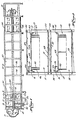
- the apparatus generally indicated at 10 has an upper horizontal cooling tunnel 11 and a lower horizontal cooling tunnel 12, both of generally rectangular cross-section through which filled flexible bags on carriers 13 are moved in a horizontal direction during a cooling operation.
- the carriers are loaded and unloaded with bags B (see Figure 10) at the left end of the apparatus and are moved, when loaded, from left to right through the upper cooling tunnel 11 and returned from right to left through the lower cooling tunnel 12.
- bags B see Figure 10
- they are attached to a pair of endless chains 15, 16 which are driven (clockwise as viewed in Figure 1) about two pairs of sprockets 17 and 18 mounted for rotation on horizontal shafts 17a and 18a.
- the cooling area consists of the upper and lower cooling tunnels 11, 12.
- water is sprayed on the bags as they move through the cooling tunnels.
- the water is distributed through a network of pipes which also serves as a significant portion of the framing structure for the cooling tunnels.
- Water for the upper cooling tunnel 11 is supplied under pressure through an inlet 19
- water for the lower cooling tunnel 12 is supplied under pressure through an inlet 21.
- the water for the upper cooling tunnel 11 is coupled through the inlet 19 to an upper manifold pipe 22 and a lower manifold pipe 23, each of which extend longitudinally along the upper cooling tunnel 11.
- each transverse spray pipe 27 has a series of spray nozzles 29 directed generally downwardly for spraying water onto the bags, and each transverse spray pipe 28 has a series of nozzles 31 generally upwardly directed for the same purpose.
- the lower cooling tunnel 12 has a similar transverse spray pipes 32 and 33 with nozzles for directing a water spray onto the bags in the carriers.
- Additional support for the cooling arrangement 10 is provided by a series of uprights 34, 36 which receive the longitudinal manifold pipes 22-26.
- the upper and lower cooling tunnels 11, 12 are enclosed by stainless steel panels indicated generally as 37 which are supported by the framework of water pipes.
- a run 38 for receiving the sprayed water which is directed to a drain line 39 for recirculation.
- a lower cooling tunnel run 41 directs the sprayed water from the lower cooling tunnel 12 to a drain-pipe 42.
- a typical carrier 13 for one or more flexible bags is formed of a series of generally L-shaped hangers 43 attached to a transverse bar 44.
- Stainless steel end panels 46, 47 are attached to the two endmost hangers and to the transverse bar 44.
- a second transverse bar 48 attached at each end to one of the end plates 46, 47 is pivotally received in blocks 49, 51 which are rigidly attached to oppositely disposed links of the chains 15, 16, respectively.
- Driving one pair of sprockets, such as 18, therefore rotates the endless chains 15, 16 and moves the carriers through the cooling tunnels 11 and 12.
- connection point is horizontally spaced apart from the track 52 along the axis of the axle 54, with the other end of the arm 56 being rigidly attached to the bar 48 and the other end of the arm 57 being rigidly attached to the bar 44. Consequently, as the track 52 and axle 54 move vertically, since the bar 48 is retained within the blocks 49, 51, the carrier 13 rotates about the longitudinal axis of the bar 48. As illustrated in Figures 5 and 7, the track 52 is moved downwardly, and therefore the transverse bar 44 is moved downwardly relative to the transverse bar 48, rocking the carrier backwardly to a position as shown in Figure 10. Raising the track 52 rocks the carrier forwardly into a position generally as shown for the carriers in Figure 9.
- the track 52 extends substantially for the length of the upper cooling tunnel 11 and is pivotally attached at points 59 to arms 58 of crank arrangements designated generally 61, which are pivotally attached for rotation about a horizontal axis at 62 to the uprights 34, 36.
- Another arm 63 of each crank arrangement 61 is pivotally attached at 64 to a linkage 66 extending generally parallel to and coextensive with the track 52.
- the linkage 66 is horizontally reciprocated by a pair of hydraulic cylinders 67, 68, which serve to raise and lower the track 52 above and below the position in which the carriers are untilted (which is illustrated in Figure 4).
- the bag loading and unloading area of the cooling arrangement 10 the roller 53 on each carrier is not yet in the vertically movable track 52 and is first received in a flared opening 69 of a fixed arcuate track section 71.
- an intermediate straight track section 72 is provided in order to interface between the fixed track section 71 and the vertically moving track 52.
- the intermediate track 72 is pivotally attached to a bracket 73 mounted on a linkage support 74.
- the linkage support 74 extends between the first pair of uprights 34, 36 and also supports the hydraulic cylinder 67 which drives the linkage 66.
- the other end of the intermediate track 72 is pivotally attached at 76 to an extending portion 77 of the track 52.
- a lower vertically movable track 78 corresponding to the track 52, provides the rocking motion for the carriers as they move through the lower horizontal cooling tunnel 12.
- the lower track 78 is terminated by intermediate tracks in the same manner as is the upper track 52, and it is also similarly hydraulically driven, although preferably the upper and lower hydraulic drives operate to rock the carriers in opposite directions.
- asymmetric stabilising rollers 79, 81 are provided at opposite sides of each carrier.
- the stabilising roller 79 is received in a flared opening 82 of a fixed arcuate track 83
- the stabilising roller 81 is received in a flared opening 84 of a fixed arcuate track 86.
- the asymmetrical positioning of the stabilising rollers provides the requisite stability for unloading the cooled bags from the carriers when they reach the unloading area.
- FIGs 11 and 1 1a there is illustrated an alternative, carrier drive and rocking arrangement.
- the bag-carrying portion of the carrier 87 is substantially the same as for the carrier 13.
- the carrier 87 has a transverse bar 88, extending across a cooling tunnel laterally, to which the remaining carrier elements are rigidly attached.
- the transverse bar 88 rotatably receives and is supported by a pair of rollers 89 which travel through the cooling tunnel on tracks 91.
- the shaft 88 is also rotatably received in a pair of blocks 92 which are rigidly attached to endless chain drives 93, substantially identical to the chain drives 15, 16.
- a crank arm 94 on one side of the carrier is fixed to an extension of the bar 88 and has a horizontal offset pin 96 terminating in a rotatable roller 97.
- the roller 97 is carried in a track 98, which extends horizontally through the cooling tunnel and which is vertically movable by a linkage arrangement 99. Vertical movement of the track 98 rotates the crank arm 94 and the bar 88 to effect rocking of the carrier 87.
- the linkage arrangement 99 in this instance is located generally below and laterally of the carriers and includes a horizontally reciprocal linkage 101.
- a series of right-angle crank elements are each pivotally attached for rotation about a horizontal axis at a point such as 102 to a different support post or other structural member of the cooling arrangement.
- Each crank element has a first arm 103 pivotally. attached to the linkage 101 and a second arm 104 pivotally attached to a pair of vertical legs 106 fixed to the track 98.
- the track 98 is raised and lowered, thereby turning each carrier crank arm 94 and rotating each carrier about its axis, the rod 88, counterclockwise and clockwise respectively, as viewed in Figure 11a.
- the track 98 is raised and lowered by longitudinally reciprocating the linkage 101 alternatively in opposite horizontal directions, which rotates each crank arm 104 in the series of crank elements along the track about its pivot 102. This rotation raises and lowers the end of the arm 104 and thus the track 98.
- FIGs 12 and 13 diagrammatically illustrate two possible forms for the distribution of a cooling medium to be sprayed into the cooling tunnels.
- the cooling medium is a water spray in an air environment.
- the water recovered from the cooling tunnels through the drains 39 and 42 is pumped through a chiller or other cooling arrangement and returned to both the upper and lower water inlets 19 and 21.
- chilled water is supplied to both cooling tunnels.
- a positive tilt angle for a carrier may be regarded as forward tilting (as illustrated in Figure 9).
- Rearward tilting may be regarded as a negative tilt angle.
- the amount of horizontal travel leftward and rightward of the linkage 66 is established.
- the positive and negative tilt angles are equal.
- the positive and negative tilt angles be the same; and while a linear transfer between positive and negative tilt angles has been illustrated, such linearity is not required.
- the transition between tilt angles should, however, be sufficiently smooth to permit the flow of the fluid material from a side of the bag at the positive tilt angle position (such as illustrated in Figure 9) to the opposite side of the bag at a negative tilt angle position (as illustrated in Figure 10).
- the ftow pattern achieved in preferred operation is in the nature of a "figure 8", laid on its side, as the fluid material in each bag flows and mixes during the rocking.
- the effectiveness of rocking increases also as the viscosity of the material in a bag being rocked increases.
- the longer dwell time for the higher viscosity fluid is required to permit time for the completion of the flow of the fluid to the lowered end of the bag after tilting.
- Figure 15 illustrates graphically the average final temperatures for two different bagged fluid food materials over a range of tilt angles.
- the two products are diced tomatoes and the more viscous yogurt fruit.
- the bag size and content volume as well as cooling conditions were substantially the same for the two products.
- the more viscous yogurt fruit completes the cooling process at a higher temperature than the less viscous diced tomatoes.
- a larger tilt angle is required.
- the two curves shown are typical of a family of curves representative of increasing viscosity, moving from the origin outwardly through the illustrated quadrant.
- a figure of merit, a heat transfer coefficient h may be derived from the following expression: In this formula, and the succeeding formulas, the terms have the meanings and units given in Table 1.
- the log mean temperature difference between the heated product and the cooling medium may be expressed as follows: Rearranging equation 1, and substituting for ⁇ T m from equation 2, yields: Equivalently, the cooling time t may be expressed as:
- the heat transfer coefficient h may be regarded as a rate of heat removal parameter, per log mean temperature differential.
- the coefficient h has significance in regard to the evaluation of the present cooling arrangement in that it is a quality factor of heat transfer efficiency which may be derived for a given set-up of the cooling arrangement.
- the heat transfer coefficient h is dependent upon the rate of air flow, the rate of water flow for the cooling spray, and the tilt angles, dwell times, and transfer times of the carriers. Variations in product weight and specific heat, water temperature and initial and final product temperatures, and cooling time are accounted for since they are factors of the equations.
- the described cooling apparatus is suitable for use for a variety of viscous materials.
- Three general material categories are particularly amenable to the described cooling techniques: 1) fluid food products, (e.g., tomato sauce, tomato paste, fruit juices, syrups), 2) particulate products in a slurry (e.g., yogurt fruits, jams, jellies, and 3) discrete product particles, (e.g. diced tomato, carrot, beet, peach or pineapple and sliced pear, peach or apple).
- a preferred bag for use in the described cooling arrangement is, when unfilled, rectangular, flat, and flexible, with a generally tubular fitment projecting from one wall through which the bag is filled and sealed with a suitable configured cap.
- rectangular bag walls of which there are two, are heat-sealed along their perimeter.
- Each wall includes three separate sheets.
- the outer sheet of each wall is in the form of a laminate consisting of .0006 inch thick biaxially-oriented Nylon on the outside, .002 inch thick nonoriented blown polyethylene homopolymer on the inside, and a layer of aluminum type-E foil .00035 inch thick in the middle.
- the inner two remaining sheets of the three-sheet wall are identical, physically separate, .002 inch thick nonoriented polyethylene sheets.
- the three-ply outer sheet, as well as the two nonlaminated separate polyethylene sheets are heat-sealed together about the rectangular periphery of the bag.
- viscosity has been used herein with regard to flowable materials to be cooled in the described cooling system, certain materials of a fibrous or pulpy nature, while not exhibiting high viscosity in a conventional sense, can be satisfactorily cooled in bags using the invention. Accordingly, the term viscosity, as used herein, shall be understood to include reference to pulpy and/or fibrous materials.
Landscapes
- Engineering & Computer Science (AREA)
- Chemical & Material Sciences (AREA)
- Life Sciences & Earth Sciences (AREA)
- Polymers & Plastics (AREA)
- Zoology (AREA)
- Food Science & Technology (AREA)
- Wood Science & Technology (AREA)
- Combustion & Propulsion (AREA)
- Physics & Mathematics (AREA)
- Mechanical Engineering (AREA)
- Thermal Sciences (AREA)
- General Engineering & Computer Science (AREA)
- Freezing, Cooling And Drying Of Foods (AREA)
Description
- This invention relates generally to heating and cooling of fluids and more particularly, concerns a cooling arrangement for a heated fluid food material in a flexible bag.
- There are various advantages, such as reduced weight, reduced shipping costs and reduced storage requirements for empty containers prior to filling, in packaging certain food products in flexible bags rather than cans. Typical products for such packaging include, for example, crushed pineapple, tomato paste, and diced tomatoes in the form of a viscous water- containing fluid.
- In handling food products, a primary concern is sterilisation, both of the food and of the container in which it is packaged. Past practice in filling a flexible bag with a food product has been to first sterilise the bag and the food through heating. Subsequently, the food is cooled and the sterile bag is filled with cooled, sterile food under aseptic conditions. An alternate approach to bag filling is to separately sterilise the food and fill the bag while the food is still heated, subsequently completing the sterilisation of the bag by the product. The bag is then sealed and cooled. The advantage of this alternative approach is that the bag need not be filled in an aseptic environment using sophisticated bag filling equipment.
- Cooling the food in the flexible bag is somewhat more difficult than cooling the food before it is placed in the bag. This is primarily due to the greater difficulty in cooling the innermost portion of the food in the bag, particularly, when the food is viscous. Since the bag is sealed, the food material inside cannot be stirred, mixed or dispersed in the presence of a cooling medium to effect rapid and uniform cooling. In practice, a coolant such as chilled water is sprayed onto the bag more or less continuously for a period of time, but the efficiency of heat removal decreases as the outermost portions of the food in the bag become relatively cool, while the interior portion remains relatively hot. It would be desirable to improve the efficiency of this food packaging process by reducing the time necessary for cooling the bag and its contents after filling.
- It has been proposed to vibrate a filled flexible bag containing a viscous food material in order to produce some mixing of the contents of the bag. One manner of doing this is to place filled flexible bags on a screen or the like and to vibrate the screen, thereby transferring the vibrations to the fluid filled bags. By using a screen, the bags are more or less accessible for spraying chilled water from both above and below during the cooling process. While such a vibrating arrangement does provide a certain amount of agitation of the contents of the bag, it does not significantly affect the problem of a "hot spot" at the centre of the bag contents.
- In FR-A-2162606 and US-A-3389568, apparatus to rock/oscillate cans are disclosed in order to produce some mixing of the contents of the rigid can. Simple oscillation however, does not really accomplish flow of the contents to eliminate the "hot spot" at the centre of the can.
- It is consequently an object of the present invention to provide a cooling arrangement for a heated fluid food material in a flexible bag, particularly a food material of substantial viscosity, so as to produce a more uniform temperature distribution throughout the fluid as it is cooled to thereby reduce the amount of time necessary to cool the fluid food material to a desired temperature.
- A cooling apparatus for heated flowable material in a container in accordance with the invention comprises a carrier for each container, means to rock the carriers and means for cooling the containers in a cooling area characterised in that the rocking means are adapted to impart a rocking motion to the carriers adapted to support containers in the form of flexible bags (B) so that the flowable material flows to different areas in each bag, altering the shape of the bag, and thereby producing enhanced heat transfer and a more uniform temperature distribution throughout the material as it is cooled. The cooling area may be defined by a framework of pipes for a cooling medium which serve the additional function of a framework for the cooling area.
- The cooling effect may be enhanced by drawing air through a portion of the cooling area to enhance evaporative cooling of water on the bags and to lower the water temperature.
- In accordance with an aspect of the invention, a method for cooling a heated flowable material in a flexible bag comprises the steps of moving the bag in a carrier through a cooling area, dispensing a cooling medium about the bag as it is moved through the cooling area, and imparting a rocking motion to the bag by way of the carrier so that the flowable material flows to different areas in the bag, altering the shape of the bag, thereby producing enhanced heat transfer and a more uniform temperature distribution throughout the material as it is cooled.
- Whilst the invention is discussed with reference to cooling heated food material; the material to be cooled may, of course, be other than food.
- The invention will now be further described by way of example with reference to the accompanying drawings, in which:-
- Figure 1 is a side view of one embodiment of cooling apparatus in accordance with the present invention, with portions removed;
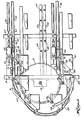
- Figure 2 is a cross-sectional view of the apparatus of Figure 1 taken along the line 2-2 of Figure 1 and showing bag carriers therein;
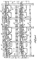
- Figure 3 is an enlarged side view of the front portion of the cooling apparatus of Figure 1;
- Figure 4 is a side view of the central portion of the cooling arrangement of Figure 1 with a section removed;
- Figure 5 is an enlarged side view of an end of the linkage support mechanism of Figure 3;
- Figure 6 is a sectional view taken along the line 6-6 of Figure 5;
- Figure 7 is a sectional view taken along the line 7-7 of Figure 5 and showing a portion of a carrier in relation to the linkage support mechanism;
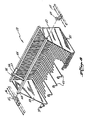
- Figure 8 is a perspective view of a carrier;
- Figures, 9, 9a, 10 and 10a show a series of bags in carriers rocked by the linkage mechanism forwardly and rearwardly, respectively;
- Figures 11 and 11 a show an alternative carrier drive and rocking arrangement;
- Figures 12 and 13 show alternative cooling medium units;
- Figure 14 is a motion diagram for the rocking of the carriers; and
- Figure 15 is a graph of the final temperature variations of the two food products over a range of tilt angles.
- The illustrated cooling apparatus for a heated fluid, or flowable, food material in a flexible bag includes a carrier for the bag and a cooling area containing a cooling medium and the carrier and bag, with means for imparting a rocking motion to the bag by way of the carrier so that the fluid food material flows to different areas in the bag, altering the shape of the bag, thereby producing enhanced cooling rates and a more uniform temperature distribution throughout the fluid as it is cooled.
- The cooling apparatus includes a pair of cooling tunnels which comprise the cooling area, in which the cooling tunnels comprise sheet metal panels which are structurally supported, at least in part, by pipes carrying water (to serve as a cooling medium) to and from the cooling tunnels. In addition, one of the cooling tunnels may be supplied with unchilled water and receive an enhanced cooling effect by drawing air through the tunnel to provide evaporative cooling of the cooling medium on the bag as well as a reduction in temperature of the cooling medium.
- Referring to the drawings, the apparatus generally indicated at 10 has an upper
horizontal cooling tunnel 11 and a lowerhorizontal cooling tunnel 12, both of generally rectangular cross-section through which filled flexible bags oncarriers 13 are moved in a horizontal direction during a cooling operation. As viewed in Figure 1, the carriers are loaded and unloaded with bags B (see Figure 10) at the left end of the apparatus and are moved, when loaded, from left to right through theupper cooling tunnel 11 and returned from right to left through thelower cooling tunnel 12. In order to move the carriers as described, they are attached to a pair ofendless chains sprockets horizontal shafts 17a and 18a. - The cooling area consists of the upper and
lower cooling tunnels upper cooling tunnel 11 is supplied under pressure through aninlet 19, and water for thelower cooling tunnel 12 is supplied under pressure through aninlet 21. The water for theupper cooling tunnel 11 is coupled through theinlet 19 to anupper manifold pipe 22 and alower manifold pipe 23, each of which extend longitudinally along theupper cooling tunnel 11. In order to spray water onto the bags in the carriers, a series of transverse upper spray pipes 27 andlower spray pipes 28 communicate with the upper andlower manifolds transverse spray pipe 28 has a series ofnozzles 31 generally upwardly directed for the same purpose. Thelower cooling tunnel 12 has a similartransverse spray pipes - Additional support for the
cooling arrangement 10 is provided by a series ofuprights lower cooling tunnels upper cooling tunnel 11 is arun 38 for receiving the sprayed water which is directed to adrain line 39 for recirculation. Similarly, a lower cooling tunnel run 41 directs the sprayed water from thelower cooling tunnel 12 to a drain-pipe 42. - With reference now in particular to Figure 8, a
typical carrier 13 for one or more flexible bags is formed of a series of generally L-shaped hangers 43 attached to atransverse bar 44. Stainlesssteel end panels transverse bar 44. In order to couple thecarrier 13 to thechains transverse bar 48, attached at each end to one of theend plates blocks chains endless chains cooling tunnels - As the carriers are moved through the cooling tunnels, they are rocked about an axis running longitudinally through the
transverse bar 48. In order to do this, a force is applied through a horizontally disposed, vertically movingtrack 52 disposed parallel to the upper reach of the chain 16 (Figures 5 and 7), to rock the carrier about thebar 48. The vertical motion of thetrack 52 is imparted to thecarrier 13 through aroller 53 in the track which is rotatably received on ahorizontal axle 54 attached to a carrier support structure made up ofarms 56 and 57 (Fig. 8). Thearms track 52 along the axis of theaxle 54, with the other end of thearm 56 being rigidly attached to thebar 48 and the other end of thearm 57 being rigidly attached to thebar 44. Consequently, as thetrack 52 andaxle 54 move vertically, since thebar 48 is retained within theblocks carrier 13 rotates about the longitudinal axis of thebar 48. As illustrated in Figures 5 and 7, thetrack 52 is moved downwardly, and therefore thetransverse bar 44 is moved downwardly relative to thetransverse bar 48, rocking the carrier backwardly to a position as shown in Figure 10. Raising thetrack 52 rocks the carrier forwardly into a position generally as shown for the carriers in Figure 9. - The
track 52 extends substantially for the length of theupper cooling tunnel 11 and is pivotally attached atpoints 59 toarms 58 of crank arrangements designated generally 61, which are pivotally attached for rotation about a horizontal axis at 62 to theuprights arm 63 of each crankarrangement 61 is pivotally attached at 64 to alinkage 66 extending generally parallel to and coextensive with thetrack 52. In the illustrated form of the cooling arrangement, thelinkage 66 is horizontally reciprocated by a pair ofhydraulic cylinders track 52 above and below the position in which the carriers are untilted (which is illustrated in Figure 4). - As best shown in Figure 3, the bag loading and unloading area of the
cooling arrangement 10 theroller 53 on each carrier is not yet in the verticallymovable track 52 and is first received in a flared opening 69 of a fixedarcuate track section 71. In order to interface between the fixedtrack section 71 and the vertically movingtrack 52, an intermediatestraight track section 72 is provided. At one end, theintermediate track 72 is pivotally attached to abracket 73 mounted on alinkage support 74. Thelinkage support 74 extends between the first pair ofuprights hydraulic cylinder 67 which drives thelinkage 66. The other end of theintermediate track 72 is pivotally attached at 76 to an extendingportion 77 of thetrack 52. Therefore, as thetrack 52 swings, substantially vertically, as driven by thelinkage 66 through thecrank mechanism 61, a continuous path for therollers 53 on the carriers is provided by theintermediate track 72 from the flared arcuate fixedtrack section 71 to the movingtrack 52. - A lower vertically movable track 78, corresponding to the
track 52, provides the rocking motion for the carriers as they move through the lowerhorizontal cooling tunnel 12. The lower track 78 is terminated by intermediate tracks in the same manner as is theupper track 52, and it is also similarly hydraulically driven, although preferably the upper and lower hydraulic drives operate to rock the carriers in opposite directions. - The exact manner of providing the drive for the
linkages 66 to effect rocking of the carriers is not critical and may be accomplished by appropriate hydraulic control, a cam arrangement, or numerical control techniques. Similarly, the selection of the drive for the chain sprockets is a matter of choice, with the drive preferably being supplied at thefront sprocket axle 17a. - For the purpose of stabilising the carriers as they are brought through the load/unload area of the cooling arrangement,
asymmetric stabilising rollers roller 79 is received in a flaredopening 82 of a fixedarcuate track 83, and the stabilisingroller 81 is received in a flaredopening 84 of a fixedarcuate track 86. The asymmetrical positioning of the stabilising rollers provides the requisite stability for unloading the cooled bags from the carriers when they reach the unloading area. - In Figures 11 and 1 1a, there is illustrated an alternative, carrier drive and rocking arrangement. The bag-carrying portion of the
carrier 87 is substantially the same as for thecarrier 13. Thecarrier 87 has atransverse bar 88, extending across a cooling tunnel laterally, to which the remaining carrier elements are rigidly attached. Thetransverse bar 88 rotatably receives and is supported by a pair ofrollers 89 which travel through the cooling tunnel on tracks 91. Theshaft 88 is also rotatably received in a pair ofblocks 92 which are rigidly attached to endless chain drives 93, substantially identical to the chain drives 15, 16. Only one side of acarrier 87 and its associatedsupport track 91 and drive chain coupling has been illustrated, but is should be understood that there are corresponding elements on the other side of the carrier so that it is supported for horizontal movement through a cooling tunnel. Acrank arm 94 on one side of the carrier is fixed to an extension of thebar 88 and has a horizontal offsetpin 96 terminating in arotatable roller 97. Theroller 97 is carried in atrack 98, which extends horizontally through the cooling tunnel and which is vertically movable by alinkage arrangement 99. Vertical movement of thetrack 98 rotates thecrank arm 94 and thebar 88 to effect rocking of thecarrier 87. - In order to permit freer spraying of the carriers, the
linkage arrangement 99 in this instance is located generally below and laterally of the carriers and includes a horizontallyreciprocal linkage 101. A series of right-angle crank elements are each pivotally attached for rotation about a horizontal axis at a point such as 102 to a different support post or other structural member of the cooling arrangement. Each crank element has afirst arm 103 pivotally. attached to thelinkage 101 and a second arm 104 pivotally attached to a pair ofvertical legs 106 fixed to thetrack 98. - In order to rock the carriers, the
track 98 is raised and lowered, thereby turning each carrier crankarm 94 and rotating each carrier about its axis, therod 88, counterclockwise and clockwise respectively, as viewed in Figure 11a. Thetrack 98 is raised and lowered by longitudinally reciprocating thelinkage 101 alternatively in opposite horizontal directions, which rotates each crank arm 104 in the series of crank elements along the track about itspivot 102. This rotation raises and lowers the end of the arm 104 and thus thetrack 98. - Figures 12 and 13 diagrammatically illustrate two possible forms for the distribution of a cooling medium to be sprayed into the cooling tunnels. In the illustrted forms, the cooling medium is a water spray in an air environment. In the Figure 12 system, shown in connection with the inlets and drains of the
cooling apparatus 10 of Figure 1, the water recovered from the cooling tunnels through thedrains lower water inlets cooling arrangement 10, chilled water is supplied to both cooling tunnels. - In Figure 13, only the lower cooling tunnel water is cooled, and the water in the upper cooling tunnel is merely recirculated. In addition, a
fan 112 draws air horizontally through the cooling tunnels and exhausts it through an exhaust 113. In this form of the cooling apparatus, less water cooling capacity is required. Drawing the air through the cooling tunnels provides evaporative cooling of water on the surface of the bags as well as cooling of the water in transit to the bags. The temperature differential between unchilled water and the bag contents is, of course, higher in the upper cooling tunnel, which is the first cooling tunnel traversed by the heated bags after they are loaded into thecooling arrangement 10. Therefore, if an arrangement such as is illustrated in Figure 13 is utilised, the cooling tunnel receiving chilled water is preferably the lower cooling tunnel, or the second tunnel traversed by the bags to be cooled. - The preferred pattern for the rocking motion of the carriers is illustrated in Figure 14. For purposes of definition, a positive tilt angle for a carrier may be regarded as forward tilting (as illustrated in Figure 9). Rearward tilting may be regarded as a negative tilt angle. In order to set a positive and negative tilt angle for each carrier (which will be substantially the same for all carriers in a given cooling tunnel since most will have a
roller 53 intrack 52 or 78), the amount of horizontal travel leftward and rightward of thelinkage 66 is established. As illustrated in Figure 14, preferably the positive and negative tilt angles are equal. - Also, once the full desired positive tilt angle is obtained, there is a dwell period followed by a transfer period when the carriers are rocked to the negative tilt angle position, in which position there is another dwell period before transferring the carriers back to the positive tilt angle position.
- While it is preferred, it is not essential that the positive and negative tilt angles be the same; and while a linear transfer between positive and negative tilt angles has been illustrated, such linearity is not required. The transition between tilt angles should, however, be sufficiently smooth to permit the flow of the fluid material from a side of the bag at the positive tilt angle position (such as illustrated in Figure 9) to the opposite side of the bag at a negative tilt angle position (as illustrated in Figure 10). The ftow pattern achieved in preferred operation is in the nature of a "figure 8", laid on its side, as the fluid material in each bag flows and mixes during the rocking. As shown in Figure 9a, for a positive tilt angle, the flowable material in a bag B flows downwardly and leftwardly, increasing the volume of material in that portion of the bag and altering the shape of the bag. As the material continues to flow to the lowered portion of the bag, the bag contents already there move upwardly and rightwardly, generally establishing a flow path is indicated by the arrows in Figure 9a. The analogous flow for fluid in a bag at a negative tilt angle is illustrated in Figure 10a. In both cases, the upper portion of the bag B, containing a lesser volume of the flowable material, is the area of maximum cooling.
- The efficiency of cooling due to rocking the filled flexible bags increases as the volume of material in a bag increases and also as the viscosity of the material in a bag increases. Bags containing 30 US Gallons of heated fluid food material have been cooled using the present cooling arrangement, and it is probable that bags containing up to 40 or even 50 US Gallons may be cooled using this technique. As the fluid volume in a bag increases, the tilt angles must be reduced to avoid bag rollover or undesirable movement of a bag in the carrier. Increasing the volume of material in bags in the carriers does not require a significant adjustment of the dwell time, merely the above-mentioned reduction of tilt angle.
- As mentioned, the effectiveness of rocking increases also as the viscosity of the material in a bag being rocked increases. In general, it is desirable to increase both the rocking angles and the dwell times for a given volume of fluid in a bag as the viscosity of the fluid in the bag increases. There is a limit to the achievable tilt angles in that creasing of the bag due to too great a tilt angle must be avoided. The longer dwell time for the higher viscosity fluid is required to permit time for the completion of the flow of the fluid to the lowered end of the bag after tilting.
- Figure 15 illustrates graphically the average final temperatures for two different bagged fluid food materials over a range of tilt angles. The two products are diced tomatoes and the more viscous yogurt fruit. The bag size and content volume as well as cooling conditions were substantially the same for the two products. As can be seen for a given tilt angle, the more viscous yogurt fruit completes the cooling process at a higher temperature than the less viscous diced tomatoes. Similarly, to attain a given average final temperature for the more viscous yogurt fruit, a larger tilt angle is required. The two curves shown are typical of a family of curves representative of increasing viscosity, moving from the origin outwardly through the illustrated quadrant.
- A figure of merit, a heat transfer coefficient h, may be derived from the following expression:


- ATr,,, the log mean temperature difference between the heated product and the cooling medium, may be expressed as follows:

equation 2, yields: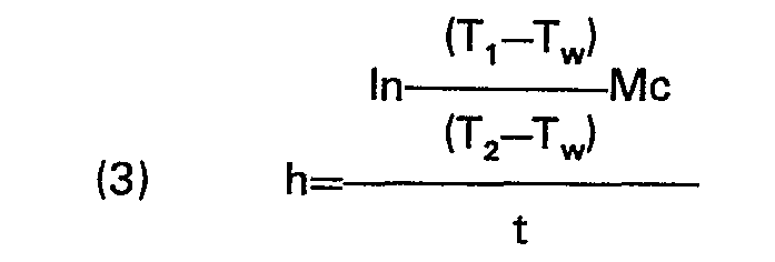

- The heat transfer coefficient h may be regarded as a rate of heat removal parameter, per log mean temperature differential. The coefficient h has significance in regard to the evaluation of the present cooling arrangement in that it is a quality factor of heat transfer efficiency which may be derived for a given set-up of the cooling arrangement. In practice, for a given cooling arrangement, the heat transfer coefficient h is dependent upon the rate of air flow, the rate of water flow for the cooling spray, and the tilt angles, dwell times, and transfer times of the carriers. Variations in product weight and specific heat, water temperature and initial and final product temperatures, and cooling time are accounted for since they are factors of the equations.
- With a 35° tilt angle, and with nine second dwell times and one second transfer times, and with 34°F water for cooling, heat transfer coefficients on the order of 0.6 to 0.9 BTU per °F-min., have been obtained. Utilising an empirically determined value for h of 0.628 BTU per °F-min., it can be calculated that a 50 lb., bag of a fluid material having a specific heat of 0.8 may be cooled from an initial temperature of 190°F to a temperature of 95°F in about 59.8 minutes. It has also been empirically determined that the heat transfer coefficient for the cooling arrangement in the case of no bag rocking may be estimated at approximately 0.3 to 0.5 BTU per °F-min. The resultant calculated cooling time for such a heat transfer coefficient would range between 75 and 125 minutes for the same weight, specific heat, and temperatures as above.
- The described cooling apparatus is suitable for use for a variety of viscous materials. Three general material categories are particularly amenable to the described cooling techniques: 1) fluid food products, (e.g., tomato sauce, tomato paste, fruit juices, syrups), 2) particulate products in a slurry (e.g., yogurt fruits, jams, jellies, and 3) discrete product particles, (e.g. diced tomato, carrot, beet, peach or pineapple and sliced pear, peach or apple).
- A preferred bag for use in the described cooling arrangement is, when unfilled, rectangular, flat, and flexible, with a generally tubular fitment projecting from one wall through which the bag is filled and sealed with a suitable configured cap. In one instance rectangular bag walls, of which there are two, are heat-sealed along their perimeter. Each wall includes three separate sheets. The outer sheet of each wall is in the form of a laminate consisting of .0006 inch thick biaxially-oriented Nylon on the outside, .002 inch thick nonoriented blown polyethylene homopolymer on the inside, and a layer of aluminum type-E foil .00035 inch thick in the middle. The inner two remaining sheets of the three-sheet wall are identical, physically separate, .002 inch thick nonoriented polyethylene sheets. As indicated, the three-ply outer sheet, as well as the two nonlaminated separate polyethylene sheets, are heat-sealed together about the rectangular periphery of the bag.
- Available sizes of bags include 3.0, 4.5 and 30 US Gallons. The rectangular bag walls of the 4.5 US Gallon bag, for example, have interior dimensions of about 18.6 inches by 22.5 inches. The filler opening is about 63 mm., in diameter. When filled and placed in an untilted carrier, the bag has a "pillow height" of about 3.5 inches, with the tubular fitment height being about 4.5 inches above the bottom of the bag.
- While the term viscosity has been used herein with regard to flowable materials to be cooled in the described cooling system, certain materials of a fibrous or pulpy nature, while not exhibiting high viscosity in a conventional sense, can be satisfactorily cooled in bags using the invention. Accordingly, the term viscosity, as used herein, shall be understood to include reference to pulpy and/or fibrous materials.
Claims (13)
Applications Claiming Priority (2)
| Application Number | Priority Date | Filing Date | Title |
|---|---|---|---|
| US06/286,065 US4384463A (en) | 1981-07-23 | 1981-07-23 | Flexible bag cooling arrangement |
| US286065 | 1981-07-23 |
Publications (2)
| Publication Number | Publication Date |
|---|---|
| EP0071417A1 EP0071417A1 (en) | 1983-02-09 |
| EP0071417B1 true EP0071417B1 (en) | 1985-01-23 |
Family
ID=23096917
Family Applications (1)
| Application Number | Title | Priority Date | Filing Date |
|---|---|---|---|
| EP82303875A Expired EP0071417B1 (en) | 1981-07-23 | 1982-07-22 | Improvements in and relating to the cooling of flexible bags |
Country Status (14)
| Country | Link |
|---|---|
| US (1) | US4384463A (en) |
| EP (1) | EP0071417B1 (en) |
| JP (1) | JPS5851882A (en) |
| AR (1) | AR231768A1 (en) |
| AU (1) | AU557452B2 (en) |
| BR (1) | BR8204314A (en) |
| CA (1) | CA1157282A (en) |
| DE (1) | DE3262048D1 (en) |
| ES (1) | ES514289A0 (en) |
| GR (1) | GR76854B (en) |
| MX (1) | MX156930A (en) |
| NZ (1) | NZ201259A (en) |
| PT (1) | PT75287A (en) |
| ZA (1) | ZA824879B (en) |
Families Citing this family (22)
| Publication number | Priority date | Publication date | Assignee | Title |
|---|---|---|---|---|
| US4505670A (en) * | 1983-03-02 | 1985-03-19 | Imdec S.R.L | Apparatus for moving and thermally conditioning cylindrical containers |
| SE446931B (en) * | 1985-02-18 | 1986-10-20 | Alfastar Ab | DEVICE FOR TRANSPORT AND HEATING OF PRODUCTS |
| US4666722A (en) * | 1985-03-18 | 1987-05-19 | Fmc Corporation | Sterile cooling method |
| US5214999A (en) * | 1992-03-30 | 1993-06-01 | Knud Simonsen Industries Limited | Zig-zag path processing facilities |
| US5370174A (en) * | 1993-06-02 | 1994-12-06 | Oak Park International, Ltd. | Method and apparatus for agitating and thermally conditioning filled containers |
| US5651191A (en) * | 1995-07-28 | 1997-07-29 | Wolverine Corporation | Material treatment system |
| US6073540A (en) | 1998-11-10 | 2000-06-13 | Fmc Corporation | Apparatus for heating or cooling product containers |
| US6387322B1 (en) | 1999-03-26 | 2002-05-14 | Timothy David Gallus | System and method for heating and then cooling contents of flexible containers |
| AU3922800A (en) * | 1999-03-26 | 2000-10-16 | Timothy David Gallus | Trough construction |
| US6340449B1 (en) * | 1999-03-26 | 2002-01-22 | Timothy David Gallus | System and method for heating or cooling contents of flexible containers |
| US6142396A (en) * | 1999-03-26 | 2000-11-07 | Gallus; Timothy David | Nozzel assembly |
| US6301905B1 (en) | 1999-03-26 | 2001-10-16 | Timothy D. Gallus | Trough construction |
| US6676541B2 (en) * | 2002-01-23 | 2004-01-13 | Acushnet Company | Co-injection molded double covered golf ball |
| US6698504B2 (en) * | 2002-04-16 | 2004-03-02 | Andrew E. Briesmeister | Apparatus and process for more rapidly cooling products contained in pouched or flexible containers |
| US20040055738A1 (en) * | 2002-04-29 | 2004-03-25 | Kauppila Richard W. | Conveyor with heat transfer arrangement |
| US7575043B2 (en) * | 2002-04-29 | 2009-08-18 | Kauppila Richard W | Cooling arrangement for conveyors and other applications |
| EP1543277A4 (en) * | 2002-08-16 | 2010-07-21 | Boc Group Inc | METHOD AND APPARATUS FOR FREEZING FOOD PRODUCTS WITH FORMATION OF A SUPERFICIAL CRUISE |
| US7464559B2 (en) * | 2005-10-07 | 2008-12-16 | Stokely-Van Camp, Inc. | Bottle cooler and method |
| US8177415B1 (en) * | 2006-07-24 | 2012-05-15 | Tarpaulin.Com, Inc. | System for agitating pouched products |
| DE102009053321B4 (en) * | 2009-11-17 | 2013-11-07 | Thomas Völkl | Frost cabinet |
| JP6012097B2 (en) * | 2012-07-27 | 2016-10-25 | 旭工業株式会社 | Sterilization cooling device |
| GB201604062D0 (en) * | 2016-03-09 | 2016-04-20 | Cell Therapy Catapult Ltd | A device for heating or cooling a sample |
Family Cites Families (17)
| Publication number | Priority date | Publication date | Assignee | Title |
|---|---|---|---|---|
| US1835799A (en) * | 1928-05-14 | 1931-12-08 | Meyer Geo J Mfg Co | Dry heat sterilizer |
| US1948790A (en) * | 1930-09-10 | 1934-02-27 | E G Ballenger | Refrigeration system |
| US2254420A (en) * | 1939-01-24 | 1941-09-02 | Arthur L Layden | Refrigerating apparatus |
| US2454704A (en) * | 1944-10-02 | 1948-11-23 | Floyd J Mcmichael | Method and apparatus for cooling produce by alternate dipping and draining |
| FR1003745A (en) * | 1947-02-20 | 1952-03-21 | Continuous method and apparatus for the preparation of fruit preserves or the like | |
| US2597223A (en) * | 1948-11-01 | 1952-05-20 | Hawaiian Pineapple Co Ltd | Treatment of food products packaged in cylindrical containers |
| US3052559A (en) * | 1959-08-17 | 1962-09-04 | Foremost Dairies Inc | Sterilizing process |
| FR1301810A (en) * | 1960-12-08 | 1962-08-24 | Product consisting of a container of a flexible material containing liquid organic substances which are normally perishable and methods for obtaining it | |
| US3132688A (en) * | 1963-04-08 | 1964-05-12 | Welville B Nowak | Electronic cold and/or hot compress device |
| US3205543A (en) * | 1963-05-27 | 1965-09-14 | Rex Chainbelt Inc | Process and apparatus for cooling foundry sand on a vibratory conveyor |
| US3389568A (en) * | 1966-02-14 | 1968-06-25 | Carnation Co | Method and apparatus for removing processing heat from a food product in filled and closed containers |
| US3481688A (en) * | 1966-11-16 | 1969-12-02 | Reynolds Metals Co | Method and apparatus for autoclaving product-containing flexible pouch constructions or the like |
| US3464835A (en) * | 1968-05-29 | 1969-09-02 | Peregrino Mario Del Pilar Cast | Process for pasteurizing liquid products in a continuous line of plastic sachets |
| IL38326A (en) * | 1971-12-09 | 1975-03-13 | Nahir D | Method and apparatus for cooling containers containing a hot viscous comestible |
| GB1423791A (en) * | 1973-02-14 | 1976-02-04 | Stal Refrigeration Ab | Refrigeration plant |
| DE2413575A1 (en) * | 1974-03-21 | 1975-09-25 | Stahl Geb Quabeck Margarete | PROCESS AND DEVICE FOR PACKAGING MELTABLE OR LIQUID MATERIAL, IN PARTICULAR MOLTEN BITUMEN, IN FLEXIBLE CONTAINERS RESISTANT TO WATER AND MOLTEN MATERIAL |
| HU174290B (en) * | 1976-09-23 | 1979-12-28 | Elelmezesipari Tervezoe Vallal | Method and apparatus for continuous hygienic precooling particularly poultry |
-
1981
- 1981-07-23 US US06/286,065 patent/US4384463A/en not_active Expired - Fee Related
-
1982
- 1982-07-07 CA CA000406782A patent/CA1157282A/en not_active Expired
- 1982-07-08 ZA ZA824879A patent/ZA824879B/en unknown
- 1982-07-08 GR GR68694A patent/GR76854B/el unknown
- 1982-07-13 NZ NZ201259A patent/NZ201259A/en unknown
- 1982-07-21 PT PT75287A patent/PT75287A/en unknown
- 1982-07-22 JP JP57128315A patent/JPS5851882A/en active Pending
- 1982-07-22 DE DE8282303875T patent/DE3262048D1/en not_active Expired
- 1982-07-22 MX MX193702A patent/MX156930A/en unknown
- 1982-07-22 AU AU86337/82A patent/AU557452B2/en not_active Ceased
- 1982-07-22 EP EP82303875A patent/EP0071417B1/en not_active Expired
- 1982-07-23 BR BR8204314A patent/BR8204314A/en unknown
- 1982-07-23 AR AR290064A patent/AR231768A1/en active
- 1982-07-23 ES ES514289A patent/ES514289A0/en active Granted
Also Published As
| Publication number | Publication date |
|---|---|
| ES8400016A1 (en) | 1983-10-16 |
| ZA824879B (en) | 1983-04-27 |
| AR231768A1 (en) | 1985-02-28 |
| US4384463A (en) | 1983-05-24 |
| DE3262048D1 (en) | 1985-03-07 |
| CA1157282A (en) | 1983-11-22 |
| JPS5851882A (en) | 1983-03-26 |
| BR8204314A (en) | 1983-07-19 |
| NZ201259A (en) | 1986-06-11 |
| AU557452B2 (en) | 1986-12-24 |
| PT75287A (en) | 1982-08-01 |
| AU8633782A (en) | 1983-01-27 |
| EP0071417A1 (en) | 1983-02-09 |
| MX156930A (en) | 1988-10-17 |
| ES514289A0 (en) | 1983-10-16 |
| GR76854B (en) | 1984-09-04 |
Similar Documents
| Publication | Publication Date | Title |
|---|---|---|
| US4384463A (en) | Flexible bag cooling arrangement | |
| US4437315A (en) | Flexible bag cooling arrangement | |
| US6194015B1 (en) | Method for heating or cooling product containers | |
| CA2357075C (en) | Packer apparatus packing conveyor, and method | |
| US8197117B2 (en) | Method for agitating pouched products | |
| JPH11103835A (en) | Method for cooling packed food using cooling conveyor | |
| US5370174A (en) | Method and apparatus for agitating and thermally conditioning filled containers | |
| JP3527019B2 (en) | Sterilization method and sterilization device for container containing liquid food | |
| US4505670A (en) | Apparatus for moving and thermally conditioning cylindrical containers | |
| JPS62287833A (en) | Vessel conveyor | |
| EP0836574A1 (en) | A method and a package for extending the shelf life of a food | |
| US3304689A (en) | Continuous chilling and vacuum packaging device | |
| JP3286561B2 (en) | Cooling system for containerized fluid | |
| US2528680A (en) | Mechanism for filling, vacuumizing, and sealing containers | |
| CN216186631U (en) | Butter condensation conveying system in bags | |
| JP2676969B2 (en) | Can lid sterilizer | |
| JPH0363056A (en) | Sterilization using gas sterilizer of article and its device | |
| CN104494870A (en) | Food packing machine | |
| US2573725A (en) | Tunnel freezing apparatus and method | |
| CN104494942B (en) | Forming and sealing device used for hollow packaging machine of food | |
| JP2003137211A (en) | Method and apparatus for manufacturing food filling and packaging bag | |
| US2295846A (en) | Means for processing canned foods | |
| CN100493999C (en) | Cooling method for can-packaged product | |
| CN114903146A (en) | Production process of boxed thick-pulled tofu with soybean polypeptides prepared by fermentation | |
| CN223443953U (en) | Automatic packaging equipment for sauerkraut processing |
Legal Events
| Date | Code | Title | Description |
|---|---|---|---|
| PUAI | Public reference made under article 153(3) epc to a published international application that has entered the european phase |
Free format text: ORIGINAL CODE: 0009012 |
|
| AK | Designated contracting states |
Designated state(s): CH DE FR GB IT LI SE |
|
| 17P | Request for examination filed |
Effective date: 19830307 |
|
| ITF | It: translation for a ep patent filed | ||
| GRAA | (expected) grant |
Free format text: ORIGINAL CODE: 0009210 |
|
| AK | Designated contracting states |
Designated state(s): CH DE FR GB IT LI SE |
|
| REF | Corresponds to: |
Ref document number: 3262048 Country of ref document: DE Date of ref document: 19850307 |
|
| ET | Fr: translation filed | ||
| PLBE | No opposition filed within time limit |
Free format text: ORIGINAL CODE: 0009261 |
|
| STAA | Information on the status of an ep patent application or granted ep patent |
Free format text: STATUS: NO OPPOSITION FILED WITHIN TIME LIMIT |
|
| 26N | No opposition filed | ||
| PG25 | Lapsed in a contracting state [announced via postgrant information from national office to epo] |
Ref country code: GB Effective date: 19880722 |
|
| PG25 | Lapsed in a contracting state [announced via postgrant information from national office to epo] |
Ref country code: SE Effective date: 19880723 |
|
| PG25 | Lapsed in a contracting state [announced via postgrant information from national office to epo] |
Ref country code: LI Effective date: 19880731 Ref country code: CH Effective date: 19880731 |
|
| GBPC | Gb: european patent ceased through non-payment of renewal fee | ||
| PG25 | Lapsed in a contracting state [announced via postgrant information from national office to epo] |
Ref country code: FR Free format text: LAPSE BECAUSE OF NON-PAYMENT OF DUE FEES Effective date: 19890331 |
|
| REG | Reference to a national code |
Ref country code: CH Ref legal event code: PL |
|
| PG25 | Lapsed in a contracting state [announced via postgrant information from national office to epo] |
Ref country code: DE Effective date: 19890401 |
|
| REG | Reference to a national code |
Ref country code: FR Ref legal event code: ST |
|
| EUG | Se: european patent has lapsed |
Ref document number: 82303875.7 Effective date: 19890510 |