EP0071364B1 - Nuclear reactor spent fuel storage rack - Google Patents
Nuclear reactor spent fuel storage rack Download PDFInfo
- Publication number
- EP0071364B1 EP0071364B1 EP82303684A EP82303684A EP0071364B1 EP 0071364 B1 EP0071364 B1 EP 0071364B1 EP 82303684 A EP82303684 A EP 82303684A EP 82303684 A EP82303684 A EP 82303684A EP 0071364 B1 EP0071364 B1 EP 0071364B1
- Authority
- EP
- European Patent Office
- Prior art keywords
- cells
- base plate
- beams
- leveling
- foot
- Prior art date
- Legal status (The legal status is an assumption and is not a legal conclusion. Google has not performed a legal analysis and makes no representation as to the accuracy of the status listed.)
- Expired
Links
Images

Classifications
-
- G—PHYSICS
- G21—NUCLEAR PHYSICS; NUCLEAR ENGINEERING
- G21C—NUCLEAR REACTORS
- G21C19/00—Arrangements for treating, for handling, or for facilitating the handling of, fuel or other materials which are used within the reactor, e.g. within its pressure vessel
- G21C19/02—Details of handling arrangements
- G21C19/06—Magazines for holding fuel elements or control elements
- G21C19/07—Storage racks; Storage pools
-
- Y—GENERAL TAGGING OF NEW TECHNOLOGICAL DEVELOPMENTS; GENERAL TAGGING OF CROSS-SECTIONAL TECHNOLOGIES SPANNING OVER SEVERAL SECTIONS OF THE IPC; TECHNICAL SUBJECTS COVERED BY FORMER USPC CROSS-REFERENCE ART COLLECTIONS [XRACs] AND DIGESTS
- Y02—TECHNOLOGIES OR APPLICATIONS FOR MITIGATION OR ADAPTATION AGAINST CLIMATE CHANGE
- Y02E—REDUCTION OF GREENHOUSE GAS [GHG] EMISSIONS, RELATED TO ENERGY GENERATION, TRANSMISSION OR DISTRIBUTION
- Y02E30/00—Energy generation of nuclear origin
- Y02E30/30—Nuclear fission reactors
Definitions
- the invention described herein relates to the safe storage of nuclear reactor fuel assemblies and more particularly to an improved design of spent fuel racks capable of substantially increasing the storage capacity of on-site spent fuel storage pools.
- Prior designs of spent fuel racks which employ the foregoing constructions to reduce spacing between either new or spent assemblies, often include a network of channel beams connected in a square array to form multiple square openings which receive the containers or cells which house fuel assemblies as shown for example in US-A-4,042,828.
- a number of fuel assembly cells connected together in this manner form modules which are interconnected and braced to the pool walls thus providing stability against horizontal seismic loadings.
- Such bracing in conjunction with various types of structural supports at the pool floor interface have resulted in installation difficulties and potential rack displacement from a non-critical design pattern to new positions which may not meet Nuclear Regulatory Commission design criteria for spent fuel pools.
- the present invention resides in a fuel rack for storing nuclear fuel assemblies in a nuclear fuel storage pool
- a base structure including a first network of interlaced beams which form a multiplicity of square openings and a second network of interlaced beams forming square openings positioned in spaced vertical alignment with the square openings in the first network of beams
- base structure leveling means located between the fuel storage pool floor and said base structure for adjusting the base structure to a level condition and cells of a size and configuration designed to hold a fuel assembly positioned in each of said aligned square openings, said cells being open at both ends with guiding funnels at their upper ends characterized in that said cells are positioned over flow openings in a base plate supporting the first network of interlaced beams so as to permit upward flow of coolant through said cells, that outwardly directed projections are provided on the sides of said cells near the top and bottom sides thereof, and means are provided for securing said projections to the beams in the first and second network of beams to thereby provide
- Neutron absorbing material may be mounted on the cell walls, which may consist of stainless steel sheets.
- the fuel rack modules can be totally free standing without interconnections, wall bracing, or separate lower support structures.
- Leveling pads are located at various places beneath the module base to provide a level floor.
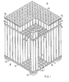
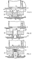
- a spent fuel rack module 15 consists of an array of containers or cells 16 each of a size and configuration for holding a nuclear fuel assembly (not shown).
- An 11 x 11 array is shown but any number of cells, including a rectangular array may be used depending on the design and configuration of the pool.
- the fuel assembly may be either a fresh or spent fuel assembly since both are of the same size and the fuel racks must be designed to meet certain criteria for storage of spent or new nuclear fuel.
- the fuel racks are of modular design and the module shown in Figs. 1 and 2, is one of many arranged to be located in a spent fuel storage pool located at the site of a nuclear reactor.
- storage pools vary in size, they generally range in depth from about 6 to 12 m and hold anywhere from two hundred to about sixteen hundred fuel assemblies.
- the pool walls are formed of reinforced concrete and are particularly designed in accordance with NRC specifications to withstand seismic forces.
- water or other coolant is circulated in heat exchange relationship with fuel rods in the assemblies in a manner well known in the art.
- the spent fuel rack module shown includes a base support structure including base plate 18 arranged to be supported from the pool floor 20 by leveling pads 22 (Fig. 9).
- the base plate of stainless steel is of sufficient thickness to carry the full weight of the cells 16 and fuel assemblies without distorting and still maintain vertical alignment of the cells positioned thereon.
- X-axis box beams 24 and Y-axis box beams 26 are mounted on and welded to base plate 18 to form lower grid structure 28.
- X-axis box beams 24 extend unbroken from one end across base plate 18 to the other side of the module, while Y-axis beams 26 include short sections which extend between and are welded to the unbroken parallel beams 24.
- Figure 4 illustrates the location and extent of welds 30 made at the intersection of the beams and the base plate.
- An upper grid structure 32 vertically displaced from lower grid structure 28, is constructed of similar box beams 34, 36.
- This interlocking arrangement of box beams in both lower and upper grid structures form multiple openings of square configuration aligned vertically to receive the stainless steel cells 16.
- the cells have walls approximately 2.5 mm thick and are open at both ends.
- the design chosen to illustrate this invention has an inner dimension of 22 cm in length and width directions and is approximately 4.3 m high.
- the bottom end of each cell welds to lower grid structure 28 which is equipped with a plurality of openings of a design well known in the art, through which coolant is adapted to flow upwardly through the fuel assemblies to carry away generated heat.
- FIGS 1 and 2 include a lower side plate 40 which extends completely around the module and is attached to base plate 18 by welds 42, and includes a weld 44 between the side plate and cell walls. These welds run along the base plate length and along the sides of the peripheral cells in the module. This arrangement imparts strength and rigidity to the lower outside areas of the module.
- the upper part of the module includes an upper side plate 46 which encompasses the complete module and is welded to each cell on the module periphery. Both peripheral plates 40, 46 encompass the cell module at low and high elevations to accurately define the module outer limits and to help impart squareness and strength to the complete module.
- the plate 46 which surrounds the module is welded along its top and bottom edges 54, 56 (Fig. 2) to those projections on the cell walls which face outwardly from the module.
- dimples 49 are formed in the walls of each cell at an elevation near the top of box beams 34, 36. These dimples may be of the design shown, or of other configuration, such as a continuous deformation of the cell wall, which projects outwardly a distance at least equal to the thickness of neutron absorbing material 64 and wrapper plates 66. Welds 51, 53 are made at the interface of the dimples and lower and upper side plates 40, 46, while welds 55, 57 are made between box beams 24, 26 and 34,36 and dimples 49.
- plates 48 are welded at 52, 54 to the cell surface but only near the upper end thereof.
- the space between cells on both X and Y axes near the base plate 18 is occupied by box beams 24, 26 of slightly larger size than box beams 34, 36 located thereabove.
- Welds 60 secure the lower box beams to the sides of cells 16 while welds 62 secure the upper box beams to the surface of plate 48.
- the depth of dimple and protective plate thickness respectively is chosen or made to a greater dimension than the combined thickness of the neutron absorbing material 64 and wrapper plate 66.
- the protective plates or dimples will therefore extend into the inter-cell space for a distance greater than the combined depth of neutron material and wrapper plate in order to protect the latter when the cells are installed in the network of lower and upper box beams which comprise the basic structure of the spent fuel racks.
- Figure 1 shows how the bottom end of cells 16 snugly fit in the aligned square openings formed by the lower and upper grid assemblies 28, 32.
- welds 58 attach the bottom edges of box beams 24, 26 to the base plate while weld 60 secures the upper edges of the box beams to the lower sides of cells 16.
- the box beams 34, 3'6 in the upper grid structure are welded at 62 along their upper edges to the protective plates 48 attached to all four sides of each cell. By welding the beams to the cell surfaces in this manner, a strong relatively rigid module is formed which not only will provide parallelism and vertical alignment between all cells but will also accommodate seismic disturbances.
- neutron absorbing material 64 mounted on the cell surface together with the space between cells which is occupied by water, or borated water, will effectively minimize neutron activity.
- the cross-sectional view in Figure 2 shows that the neutron absorbing material, preferably "Boraflex" which is boron carbide in an elastomeric silicon polymer matrix manufactured by Brand Industrial Services, Inc., of Park Ridge, Illinois, is attached to all sides of each cell. Other equivalent materials may be used if desired.
- the material 64 covers substantially the fully surface area of the cell walls but terminates just short of the sides and the top and bottom grid structures.
- a wrapper plate 66 of a size slightly larger than the material is welded to the sides of the cell by tack welds 68 to retain the neutron absorbing material. Water tightness is not essential since the neutron absorbing material used is not adversely affected by contact with the pool environment.
- the total thickness of material 64 and wrapper plate 66 is less than the thickness of the dimples 49 or protective plate 48, the purpose being that when the cells are loaded into or removed from the module, the greater thickness of dimple 49 or protective plate 48 will permit that part of the cell having the wrapper plates thereon to pass freely through the upper grid structure without damaging the wrapper plates and material 64 surfaces.
- leveling of the base plate 18 is accomplished by utilizing leveling pads 22 more fully described hereafter, positioned under plate 18 at each of the corners of the module, and beneath the selected section of plate 18, depending on the loads carried by the base plate.
- Each cell in the module is of square cross- section and of a size to fit into the complementary and vertically aligned square openings formed by the lower and upper grid structures 28, 32.
- the cell upper walls have funnel cell flanges 39 which flare outwardly to help guide a fuel assembly into the cell during the loading process.
- the upper ends terminate just above the upper grid 32 and a brace 38 shaped to the same configuration as the flared sections, is welded to the outer wall of the peripheral cells in the module.
- the brace serves a support function and helps keep the cells in proper alignment.
- Additional rigidity may be imparted to the structure by welding the shear plates mentioned above to adjacent cells 16 having their surfaces on the modular periphery.
- Each plate is of a width sufficient to bridge the gap 70 between adjacent cells and thereby overlap the cell walls which face outwardly.
- the longitudinal edges of the shear plates terminate short of wrapper plate 66 and the vertical edges on each end of the shear plates are then welded to the cell walls. This construction is repeated on adjacent cells in the outer rows in the module to provide a degree of rigidity to the complete module and, if necessary, help meet NRC seismic criteria for spent fuel racks.
- the spaced cells forming the fuel rack have their centerlines lie on the cell vertical axis to help assure unimpeded loading and removal of fuel assemblies from the fuel rack cells. This is accomplished in the design disclosed herein by providing adjustability to the base plate 18 on which the fuel assemblies rest.
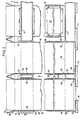
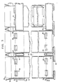
- Figures 4 through 11 show the structure needed for leveling purposes.
- Figure 4 is a plan view of a portion of base plate 18 and shows the box beams 24, 26 welded to its upper surface.
- the plate includes multiple openings 72 through which coolant flows upwardly for cooling the fuel assemblies and for providing access to leveling pads located therebeneath.
- Figure 5 shows leveling pad support plates 74 located at the base plate 18 four corners and at selected other positions beneath the plate as necessary to adequately support the load on the base plate upper surface.
- Figures 5-7 show lifting plates 76 welded to the underside of plate 18 for module lifting purposes.
- the lifting plates are about 25.4 mm thick and have rectangular openings 78 which extend upwardly through base plate 18.
- Multiple stop bars at each corner of opening 78 extend downwardly from the plate underside so that when a lifting lug is moved downwardly through a rectangular opening 78 and rotated 90° to enable lifting upwardly on the underside of the plate, the stop bars serve to preclude inadvertent movement of the lug to a position where it could slip upwardly through the plate opening.
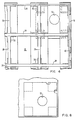
- Figure 9 shows a pool liner 20 having a pedestal 80 mounted for free unrestricted movement on the pool liner surface.
- the pedestal includes an accurate surface 82 which merges into upstanding cylindrical walls 84.
- a leveling screw 86 having a spherical surface 88 formed on its bottom end is complementary to pedestal surface 82. After the end of leveling screw 86 is placed in the pedestal, a circular plate 87 is welded to the walls 84 thus leaving a space 89 into which the end of the screw may move if necessary for leveling purposes.
- the support pad 22 includes four radically spaced support arms 97 attached to the underside of base plate 18 by welds 98.
- each pedestal 80 is moved in an amount and direction to have its bottom surface tilt or conform to the slope of the floor on which the pool liner 20 rests. If the liner floor is uneven, the complementary spherical surfaces on the pedestal and leveling screw are adjusted to each other until the axis of leveling screw 86 lies in a vertical plane. By inserting a tool in slot 96 and rotating the leveling screw, which then acts as a bearing, the support pad 22 will move vertically and thus raise or lower the base plate 18 to a desired position. This action is repeated for each corner and central area support pad until the base plate 18 is adjusted to a horizontal position.
- the support pad of Figure 10 is used in those spent fuel racks already in place which have shear studs 100 embedded in the pool floor.
- the leveling pad parts are otherwise the same and include a pedestal 80 modified to include a central opening 102 through which stud 100 projects.
- the diameter of opening 102 is sufficiently large to accommodate non-verticality in the stud 100 and variations in slope in the pool floor.
- the stud serves to maintain the position of a leveling pad in the pool floor area and subjected to shear only in the event of a large seismic disturbance, it is designed to a length to extend upwardly into the leveling screw 86 to a relatively short distance.
- a space 104 is provided between the stud and leveling screw walls to provide flexibility in fitting the parts to each other.
- the coacting threads on the screw and support pad 22 cause the support pad and base plate 18 to move vertically until a horizontal position is reached.
- the support pad of Figure 11 is likewise used in those fuel rack installations where studs are already embedded in the pool floor.
- the stud 100 extends the full length of leveling screw 86 and is topped by a spherical anchor nut 106 and anchor washer 112 which restrains the rack vertically.
- the upper end of the stud has external threads 108 to accept the threads of nut 106.
- a spherical washer 112 bears between the upper end of leveling screw 86 and the nut to provide spherical surfaces which help to compensate for the potential misalignment of the stud embedded in the pool floor.
- the pedestal seeks the floor slope and the spherical surfaces on the pedestal and leveling screw permit the leveling screw to lie in a vertical plane, all within the range of space 89 provided in the pedestal. Adjustment of the support pad 22 vertically by the leveling screw 86 causes variation in the horizontal position of base plate 18.
Description
- The invention described herein relates to the safe storage of nuclear reactor fuel assemblies and more particularly to an improved design of spent fuel racks capable of substantially increasing the storage capacity of on-site spent fuel storage pools.
- The continued delays in establishing and licensing spent nuclear fuel reprocessing facilities has required electric power generating utilities to better utilize their present spent fuel storage pools to maximize, the storage of spent fuel assemblies removed from an operating reactor. To increase the storage density of fuel assemblies, stainless steel containers or cells which house separate fuel assemblies are used to achieve reduction in fuel assembly spacing in the pool. Alternatively the spacing can be reduced to a further degree by incorporating neutron absorbing substances, such as boron carbide in the cell walls at the time of manufacture, or by attaching neutron absorbing materials to the sides of the cell as separate components. These constructions which permit closer spacing of adjacent fuel assemblies, effectively capture neutrons and keep the fissionable mass in the fuel assemblies from reaching a critical geometry while maintaining the pool temperature at acceptable levels.
- Prior designs of spent fuel racks which employ the foregoing constructions to reduce spacing between either new or spent assemblies, often include a network of channel beams connected in a square array to form multiple square openings which receive the containers or cells which house fuel assemblies as shown for example in US-A-4,042,828. A number of fuel assembly cells connected together in this manner form modules which are interconnected and braced to the pool walls thus providing stability against horizontal seismic loadings. Such bracing in conjunction with various types of structural supports at the pool floor interface have resulted in installation difficulties and potential rack displacement from a non-critical design pattern to new positions which may not meet Nuclear Regulatory Commission design criteria for spent fuel pools.
- Further since the cells and fuel assemblies are submerged in water, constructions incorporating neutron absorbing substances must utilize materials which are compatible with the pool environment or provide total encapsulation of the material. Some earlier designs of the latter type have experienced swelling of the poison cavities.
- It is the principal object of the present invention to provide a nuclear fuel rack which overcomes the above disadvantages.
- With this object in view, the present invention resides in a fuel rack for storing nuclear fuel assemblies in a nuclear fuel storage pool comprising a base structure including a first network of interlaced beams which form a multiplicity of square openings and a second network of interlaced beams forming square openings positioned in spaced vertical alignment with the square openings in the first network of beams, base structure leveling means located between the fuel storage pool floor and said base structure for adjusting the base structure to a level condition and cells of a size and configuration designed to hold a fuel assembly positioned in each of said aligned square openings, said cells being open at both ends with guiding funnels at their upper ends characterized in that said cells are positioned over flow openings in a base plate supporting the first network of interlaced beams so as to permit upward flow of coolant through said cells, that outwardly directed projections are provided on the sides of said cells near the top and bottom sides thereof, and means are provided for securing said projections to the beams in the first and second network of beams to thereby provide a substantially rigid fuel rack of modular design, the walls of each of said cells having neutron absorbing materials associated therewith.
- Neutron absorbing material may be mounted on the cell walls, which may consist of stainless steel sheets.
- The fuel rack modules can be totally free standing without interconnections, wall bracing, or separate lower support structures. Leveling pads are located at various places beneath the module base to provide a level floor.
- The invention will become more readily apparent from the following description of a preferred embodiment thereof shown, by way of example only, in the accompanying drawings, wherein:
- Figure 1 is an isometric view of a spent fuel rack module showing the disposition of cells which house fuel assemblies;
- Fig. 2 is a view illustrating the arrangement for spacing adjacent fuel assembly cells and showing how neutron absorbing material is attached to the cell walls;
- Fig. 3 is a modification of the design shown in Fig. 2;
- Fig. 4 is a plan view of one end of the base plate showing box beams and the design for providing base plate support by leveling pads;
- Fig. 5 is a bottom view of the base plate showing the location of support plates attached to the underside of the base plate;
- Fig. 6 illustrates the design of a lifting support plate shown in Fig. 5;
- Fig. 7 is a side view of the plate of Fig. 6;
- Fig. 8 illustrates the design of leveling pad used for supporting the base plate;
- Fig. 9 is a sectional view in elevation illustrating the design of leveling pad used for imparting support to the base plate;
- Fig. 10 is a sectional view in elevation showing the design of leveling pad used in spent fuel pads having alignment shear studs anchored in the pool floor; and
- Fig. 11 is a sectional view in elevation showing the design of leveling pad used with alignment studs anchored in the pool floor and extending upwardly into the leveling pad.
- As shown in Figs. 1 and 2 a spent
fuel rack module 15 consists of an array of containers orcells 16 each of a size and configuration for holding a nuclear fuel assembly (not shown). An 11 x 11 array is shown but any number of cells, including a rectangular array may be used depending on the design and configuration of the pool. The fuel assembly may be either a fresh or spent fuel assembly since both are of the same size and the fuel racks must be designed to meet certain criteria for storage of spent or new nuclear fuel. The fuel racks are of modular design and the module shown in Figs. 1 and 2, is one of many arranged to be located in a spent fuel storage pool located at the site of a nuclear reactor. Although storage pools vary in size, they generally range in depth from about 6 to 12 m and hold anywhere from two hundred to about sixteen hundred fuel assemblies. The pool walls are formed of reinforced concrete and are particularly designed in accordance with NRC specifications to withstand seismic forces. To remove heat which continues to be generated by the fuel assemblies, water or other coolant is circulated in heat exchange relationship with fuel rods in the assemblies in a manner well known in the art. - The spent fuel rack module shown includes a base support structure including
base plate 18 arranged to be supported from thepool floor 20 by leveling pads 22 (Fig. 9). The base plate of stainless steel is of sufficient thickness to carry the full weight of thecells 16 and fuel assemblies without distorting and still maintain vertical alignment of the cells positioned thereon. - To achieve the desired horizontal spacing and vertical alignment of
cells 16, intersectingX-axis box beams 24 and Y-axis box beams 26 are mounted on and welded tobase plate 18 to formlower grid structure 28. As shown in Fig. 1,X-axis box beams 24 extend unbroken from one end acrossbase plate 18 to the other side of the module, while Y-axis beams 26 include short sections which extend between and are welded to the unbrokenparallel beams 24. Figure 4 illustrates the location and extent ofwelds 30 made at the intersection of the beams and the base plate. Anupper grid structure 32 vertically displaced fromlower grid structure 28, is constructed ofsimilar box beams - This interlocking arrangement of box beams in both lower and upper grid structures form multiple openings of square configuration aligned vertically to receive the
stainless steel cells 16. The cells have walls approximately 2.5 mm thick and are open at both ends. Although the cells may be made of any size or configuration, the design chosen to illustrate this invention has an inner dimension of 22 cm in length and width directions and is approximately 4.3 m high. The bottom end of each cell welds to lowergrid structure 28 which is equipped with a plurality of openings of a design well known in the art, through which coolant is adapted to flow upwardly through the fuel assemblies to carry away generated heat. - To impart reasonable rigidity to the complete module and to maintain the same uniform distance between all cells in the module while obtaining parallelism between cell centerlines, each cell is welded on all sides to adjacent box beams in both the lower and upper grid structures as more fully described hereafter. Figures 1 and 2 include a
lower side plate 40 which extends completely around the module and is attached tobase plate 18 by welds 42, and includes aweld 44 between the side plate and cell walls. These welds run along the base plate length and along the sides of the peripheral cells in the module. This arrangement imparts strength and rigidity to the lower outside areas of the module. - Likewise, the upper part of the module includes an
upper side plate 46 which encompasses the complete module and is welded to each cell on the module periphery. Bothperipheral plates plate 46 which surrounds the module is welded along its top andbottom edges 54, 56 (Fig. 2) to those projections on the cell walls which face outwardly from the module. - As illustrated in the preferred embodiment of the invention in Fig. 3,
dimples 49 are formed in the walls of each cell at an elevation near the top ofbox beams neutron absorbing material 64 andwrapper plates 66. Welds 51, 53 are made at the interface of the dimples and lower andupper side plates welds box beams - In the alternative design of Fig. 2, in lieu of using dimples which project into the inter-cell space at both the bottom and top of the module,
plates 48 are welded at 52, 54 to the cell surface but only near the upper end thereof. The space between cells on both X and Y axes near thebase plate 18 is occupied bybox beams box beams cells 16 whilewelds 62 secure the upper box beams to the surface ofplate 48. - In both modifications which utilize dimples and
protective plates 48 to which theside plates 46 and box beams are welded, the depth of dimple and protective plate thickness respectively is chosen or made to a greater dimension than the combined thickness of theneutron absorbing material 64 andwrapper plate 66. The protective plates or dimples will therefore extend into the inter-cell space for a distance greater than the combined depth of neutron material and wrapper plate in order to protect the latter when the cells are installed in the network of lower and upper box beams which comprise the basic structure of the spent fuel racks. - Figure 1 shows how the bottom end of
cells 16 snugly fit in the aligned square openings formed by the lower andupper grid assemblies welds 58 attach the bottom edges ofbox beams weld 60 secures the upper edges of the box beams to the lower sides ofcells 16. Thebox beams 34, 3'6 in the upper grid structure are welded at 62 along their upper edges to theprotective plates 48 attached to all four sides of each cell. By welding the beams to the cell surfaces in this manner, a strong relatively rigid module is formed which not only will provide parallelism and vertical alignment between all cells but will also accommodate seismic disturbances. - In order to assure that fuel stored in the cells will not reach a critical mass,
neutron absorbing material 64 mounted on the cell surface together with the space between cells which is occupied by water, or borated water, will effectively minimize neutron activity. The cross-sectional view in Figure 2 shows that the neutron absorbing material, preferably "Boraflex" which is boron carbide in an elastomeric silicon polymer matrix manufactured by Brand Industrial Services, Inc., of Park Ridge, Illinois, is attached to all sides of each cell. Other equivalent materials may be used if desired. As shown in Figure 2, thematerial 64 covers substantially the fully surface area of the cell walls but terminates just short of the sides and the top and bottom grid structures. Awrapper plate 66 of a size slightly larger than the material is welded to the sides of the cell bytack welds 68 to retain the neutron absorbing material. Water tightness is not essential since the neutron absorbing material used is not adversely affected by contact with the pool environment. The total thickness ofmaterial 64 andwrapper plate 66 is less than the thickness of thedimples 49 orprotective plate 48, the purpose being that when the cells are loaded into or removed from the module, the greater thickness ofdimple 49 orprotective plate 48 will permit that part of the cell having the wrapper plates thereon to pass freely through the upper grid structure without damaging the wrapper plates andmaterial 64 surfaces. - One Nuclear Regulatory Commission requirement for spent fuel racks is that they must withstand seismic forces. In the present design, this is accomplished by utilizing the interconnected box beam and side plate arrangements described above. Since the upper and
lower grid structures - The foregoing discussion indicates the need to have the center line of each fuel assembly cell perpendicular to the base plate on which the cells are arranged to be positioned. In the present design, leveling of the
base plate 18 is accomplished by utilizingleveling pads 22 more fully described hereafter, positioned underplate 18 at each of the corners of the module, and beneath the selected section ofplate 18, depending on the loads carried by the base plate. - Each cell in the module is of square cross- section and of a size to fit into the complementary and vertically aligned square openings formed by the lower and
upper grid structures funnel cell flanges 39 which flare outwardly to help guide a fuel assembly into the cell during the loading process. The upper ends terminate just above theupper grid 32 and abrace 38 shaped to the same configuration as the flared sections, is welded to the outer wall of the peripheral cells in the module. The brace serves a support function and helps keep the cells in proper alignment. - Additional rigidity may be imparted to the structure by welding the shear plates mentioned above to
adjacent cells 16 having their surfaces on the modular periphery. Each plate is of a width sufficient to bridge thegap 70 between adjacent cells and thereby overlap the cell walls which face outwardly. Preferably, the longitudinal edges of the shear plates terminate short ofwrapper plate 66 and the vertical edges on each end of the shear plates are then welded to the cell walls. This construction is repeated on adjacent cells in the outer rows in the module to provide a degree of rigidity to the complete module and, if necessary, help meet NRC seismic criteria for spent fuel racks. - It is essential that the spaced cells forming the fuel rack have their centerlines lie on the cell vertical axis to help assure unimpeded loading and removal of fuel assemblies from the fuel rack cells. This is accomplished in the design disclosed herein by providing adjustability to the
base plate 18 on which the fuel assemblies rest. - The pool liners rarely are exactly flat and level and leveling means is therefore necessary to adjust
base plate 18 to a horizontal condition. Figures 4 through 11 show the structure needed for leveling purposes. Figure 4 is a plan view of a portion ofbase plate 18 and shows the box beams 24, 26 welded to its upper surface. The plate includesmultiple openings 72 through which coolant flows upwardly for cooling the fuel assemblies and for providing access to leveling pads located therebeneath. - Figure 5 shows leveling
pad support plates 74 located at thebase plate 18 four corners and at selected other positions beneath the plate as necessary to adequately support the load on the base plate upper surface. Figures 5-7show lifting plates 76 welded to the underside ofplate 18 for module lifting purposes. The lifting plates are about 25.4 mm thick and haverectangular openings 78 which extend upwardly throughbase plate 18. Multiple stop bars at each corner of opening 78 extend downwardly from the plate underside so that when a lifting lug is moved downwardly through arectangular opening 78 and rotated 90° to enable lifting upwardly on the underside of the plate, the stop bars serve to preclude inadvertent movement of the lug to a position where it could slip upwardly through the plate opening. - Referring more specifically to the arrangement for leveling
base plate 18, Figure 9 shows apool liner 20 having apedestal 80 mounted for free unrestricted movement on the pool liner surface. The pedestal includes an accurate surface 82 which merges into upstandingcylindrical walls 84. A levelingscrew 86 having aspherical surface 88 formed on its bottom end is complementary to pedestal surface 82. After the end of levelingscrew 86 is placed in the pedestal, acircular plate 87 is welded to thewalls 84 thus leaving aspace 89 into which the end of the screw may move if necessary for leveling purposes.External threads 90 on the screw mesh withsimilar threads 92 on asupport pad 22 so that when the screw is rotated by a tool inslot 96, the support pad is caused to be moved vertically. Thesupport pad 22 includes four radically spacedsupport arms 97 attached to the underside ofbase plate 18 bywelds 98. - In operation, to adjust
base plate 18 to a level condition, levelingpads 22 are located beneathbase plate 18 corners and at selected positions under the base plate central area. To level the base plate and cells thereon, eachpedestal 80 is moved in an amount and direction to have its bottom surface tilt or conform to the slope of the floor on which thepool liner 20 rests. If the liner floor is uneven, the complementary spherical surfaces on the pedestal and leveling screw are adjusted to each other until the axis of levelingscrew 86 lies in a vertical plane. By inserting a tool inslot 96 and rotating the leveling screw, which then acts as a bearing, thesupport pad 22 will move vertically and thus raise or lower thebase plate 18 to a desired position. This action is repeated for each corner and central area support pad until thebase plate 18 is adjusted to a horizontal position. - The support pad of Figure 10 is used in those spent fuel racks already in place which have
shear studs 100 embedded in the pool floor. The leveling pad parts are otherwise the same and include apedestal 80 modified to include acentral opening 102 through whichstud 100 projects. The diameter ofopening 102 is sufficiently large to accommodate non-verticality in thestud 100 and variations in slope in the pool floor. Since the stud serves to maintain the position of a leveling pad in the pool floor area and subjected to shear only in the event of a large seismic disturbance, it is designed to a length to extend upwardly into the levelingscrew 86 to a relatively short distance. As in the case of the pedestal opening, a space 104 is provided between the stud and leveling screw walls to provide flexibility in fitting the parts to each other. As a tool inslot 96 rotates the leveling screw, the coacting threads on the screw andsupport pad 22 cause the support pad andbase plate 18 to move vertically until a horizontal position is reached. - The support pad of Figure 11 is likewise used in those fuel rack installations where studs are already embedded in the pool floor. In this design, the
stud 100 extends the full length of levelingscrew 86 and is topped by aspherical anchor nut 106 andanchor washer 112 which restrains the rack vertically. The upper end of the stud hasexternal threads 108 to accept the threads ofnut 106. Aspherical washer 112 bears between the upper end of levelingscrew 86 and the nut to provide spherical surfaces which help to compensate for the potential misalignment of the stud embedded in the pool floor. As in the previous modifications, the pedestal seeks the floor slope and the spherical surfaces on the pedestal and leveling screw permit the leveling screw to lie in a vertical plane, all within the range ofspace 89 provided in the pedestal. Adjustment of thesupport pad 22 vertically by the levelingscrew 86 causes variation in the horizontal position ofbase plate 18.
Claims (5)
Applications Claiming Priority (2)
| Application Number | Priority Date | Filing Date | Title |
|---|---|---|---|
| US06/282,991 US4820472A (en) | 1981-07-14 | 1981-07-14 | Nuclear reactor spent fuel storage rack |
| US282991 | 1981-07-14 |
Publications (4)
| Publication Number | Publication Date |
|---|---|
| EP0071364A2 EP0071364A2 (en) | 1983-02-09 |
| EP0071364A3 EP0071364A3 (en) | 1984-03-28 |
| EP0071364B1 true EP0071364B1 (en) | 1988-06-01 |
| EP0071364B2 EP0071364B2 (en) | 1992-04-08 |
Family
ID=23084015
Family Applications (1)
| Application Number | Title | Priority Date | Filing Date |
|---|---|---|---|
| EP82303684A Expired - Lifetime EP0071364B2 (en) | 1981-07-14 | 1982-07-14 | Nuclear reactor spent fuel storage rack |
Country Status (8)
| Country | Link |
|---|---|
| US (1) | US4820472A (en) |
| EP (1) | EP0071364B2 (en) |
| JP (2) | JPS5828697A (en) |
| KR (1) | KR890003269B1 (en) |
| DE (1) | DE3278594D1 (en) |
| ES (1) | ES513941A0 (en) |
| FR (1) | FR2509899B1 (en) |
| YU (1) | YU45952B (en) |
Families Citing this family (34)
| Publication number | Priority date | Publication date | Assignee | Title |
|---|---|---|---|---|
| US4900505A (en) * | 1981-12-22 | 1990-02-13 | Westinghouse Electric Corp. | Spent fuel storage rack |
| US5245641A (en) * | 1981-12-22 | 1993-09-14 | Westinghouse Electric Corp. | Spent fuel storage rack |
| US4960560A (en) * | 1981-12-22 | 1990-10-02 | Westinghouse Electric Corp. | Spent fuel storage rack for BWR fuel assemblies |
| DE3270164D1 (en) * | 1981-12-22 | 1986-04-30 | Westinghouse Electric Corp | Storage rack for spent bwr fuel assemblies |
| DE3473678D1 (en) * | 1983-03-01 | 1988-09-29 | Westinghouse Electric Corp | Storage of spent nuclear fuel |
| IT1194351B (en) * | 1983-07-28 | 1988-09-22 | Snam Progetti | PROCEDURE FOR THE RECOVERY OF BUTENE-1 DEGREE POLYMERIZATION |
| FR2551907A1 (en) * | 1983-09-14 | 1985-03-15 | Lemer & Cie | DEVICE FOR STORING COMBUSTIBLE ELEMENTS IN A SWIMMING POOL |
| FR2553921A1 (en) * | 1983-10-19 | 1985-04-26 | Lemer & Cie | REMOVABLE ELEMENTS FOR RIGID STRUCTURE OF NUCLEAR FUEL STORAGE RACK |
| US5114666A (en) * | 1989-09-11 | 1992-05-19 | U.S. Tool & Die, Inc. | Cask basket construction for heat-producing radioactive material |
| DE4134246A1 (en) * | 1991-10-16 | 1993-04-29 | Siemens Ag | STORAGE RACK FOR CORE REACTOR FUEL ELEMENTS |
| US5254318A (en) * | 1992-07-20 | 1993-10-19 | Stone & Webster Engineering Corporation | Lined reformer tubes for high pressure reformer reactors |
| US5361281A (en) * | 1993-07-30 | 1994-11-01 | Aea O'donnell, Inc. | Storage rack for spent nuclear fuel assemblies |
| US6393086B1 (en) * | 1999-02-26 | 2002-05-21 | Westinghouse Electric Company Llc | Spent nuclear fuel assembly stacking method |
| FR2791171B1 (en) * | 1999-03-18 | 2004-02-06 | Atea Soc Atlantique De Tech Av | METHOD AND DEVICE FOR FIXING A LARGE-SIZED STRUCTURE ONTO A SUPPORT SURFACE AND APPLICATION TO THE REDEVELOPMENT OF A STORAGE POOL OF A NUCLEAR POWER PLANT |
| FR2813701B1 (en) * | 2000-09-01 | 2002-11-29 | Transnucleaire | STORAGE BASKET FOR RADIOACTIVE MATERIAL |
| US6741669B2 (en) | 2001-10-25 | 2004-05-25 | Kenneth O. Lindquist | Neutron absorber systems and method for absorbing neutrons |
| US7139353B2 (en) * | 2002-12-06 | 2006-11-21 | Framatome Anp Inc. | Boiling water reactor nuclear fuel assembly lifting support |
| JP5517656B2 (en) * | 2004-11-12 | 2014-06-11 | 三菱重工業株式会社 | Fuel storage rack group and fuel storage equipment |
| RU2465661C2 (en) * | 2007-10-29 | 2012-10-27 | Холтек Интернэшнл, Инк. | Apparatus for fastening radioactive fuel assemblies |
| EP2209125B1 (en) * | 2009-01-09 | 2013-05-15 | Cci Ag | Storage rack assembly for storing nuclear fuel elements |
| KR101063484B1 (en) * | 2009-08-14 | 2011-09-08 | (주) 코네스코퍼레이션 | Suspended dense storage for storing fuel assemblies |
| JP2013503353A (en) * | 2009-08-31 | 2013-01-31 | トランスニュークリア インコーポレイテッド | Rack system and assembly for fuel storage |
| JP5709400B2 (en) * | 2010-04-09 | 2015-04-30 | 三菱重工業株式会社 | Nuclear fuel storage rack and nuclear fuel storage rack group |
| JP5546374B2 (en) * | 2010-06-30 | 2014-07-09 | 三菱重工業株式会社 | Nuclear fuel storage rack |
| JP5610960B2 (en) * | 2010-09-29 | 2014-10-22 | 三菱重工業株式会社 | Nuclear fuel storage rack |
| US11515054B2 (en) | 2011-08-19 | 2022-11-29 | Holtec International | Method of retrofitting a spent nuclear fuel storage system |
| US20150221402A1 (en) * | 2011-12-22 | 2015-08-06 | Holtec International ,Inc. | Storage system for nuclear fuel |
| FR2994327B1 (en) * | 2012-08-03 | 2019-08-23 | Onet Technologies Cn | DEFORMABLE ADJUSTABLE FEET FOR STORAGE BOILER CHASSIS FOR NUCLEAR COMBUSTIBLE ASSEMBLIES |
| US9991010B2 (en) | 2012-08-28 | 2018-06-05 | Holtec International, Inc. | System and method for minimizing movement of nuclear fuel racks during a seismic event |
| JP5987019B2 (en) * | 2014-05-07 | 2016-09-06 | 三菱重工業株式会社 | Nuclear fuel storage rack and nuclear fuel storage rack group |
| JP5826325B2 (en) * | 2014-05-07 | 2015-12-02 | 三菱重工業株式会社 | Nuclear fuel storage rack and nuclear fuel storage rack group |
| JP2014145788A (en) * | 2014-05-07 | 2014-08-14 | Mitsubishi Heavy Ind Ltd | Nuclear fuel storage rack and nuclear fuel storage rack group |
| US11796255B2 (en) | 2017-02-24 | 2023-10-24 | Holtec International | Air-cooled condenser with deflection limiter beams |
| US10847274B2 (en) * | 2017-02-24 | 2020-11-24 | Holtec International | Earthquake-resistant fuel storage rack system for fuel pools in nuclear plants |
Family Cites Families (33)
| Publication number | Priority date | Publication date | Assignee | Title |
|---|---|---|---|---|
| US3533911A (en) * | 1967-04-14 | 1970-10-13 | Gulf General Atomic Inc | Nuclear reactor systems |
| US3882313A (en) * | 1972-11-07 | 1975-05-06 | Westinghouse Electric Corp | Concentric annular tanks |
| US4021300A (en) * | 1975-05-23 | 1977-05-03 | The United States Of America As Represented By The United States Energy Research And Development Administration | Improved nuclear fuel assembly grid spacer |
| US4010375A (en) * | 1975-05-27 | 1977-03-01 | Wachter William J | Storage rack for nuclear fuel assemblies |
| US4096392A (en) * | 1975-07-11 | 1978-06-20 | Nuclear Services Corporation | Rack for storing spent nuclear fuel elements |
| US4006362A (en) * | 1975-11-17 | 1977-02-01 | Brooks & Perkins, Incorporated | Shroud for storing radioactive spent nuclear fuel cells |
| US4042828A (en) * | 1975-11-17 | 1977-08-16 | Nuclear Services Corporation | Rack for nuclear fuel elements |
| US4039842A (en) * | 1976-01-08 | 1977-08-02 | Brooks & Perkins, Incorporated | Fuel storage rack |
| US4034227A (en) * | 1976-02-02 | 1977-07-05 | Olaf Soot | Nuclear fuel storage rack |
| US4024406A (en) * | 1976-02-17 | 1977-05-17 | Combustion Engineering, Inc. | Spent fuel storage improvement |
| US4068878A (en) * | 1976-09-28 | 1978-01-17 | The United States Of America As Represented By The Secretary Of The Navy | Container lift coupling |
| US4124445A (en) * | 1976-10-06 | 1978-11-07 | Brooks & Perkins, Incorporated | Storage rack for fuel cell receiving shrouds |
| JPS5356497A (en) * | 1976-10-29 | 1978-05-22 | Hitachi Ltd | Fuel storage rack for nuclear reactor |
| US4137125A (en) * | 1976-11-12 | 1979-01-30 | Westinghouse Electric Corp. | Method of welding nuclear reactor fuel assemblies |
| US4143276A (en) * | 1977-05-09 | 1979-03-06 | Brooks & Perkins, Incorporated | Spent nuclear fuel storage racks |
| US4119859A (en) * | 1977-05-23 | 1978-10-10 | Brooks & Perkins, Incorporated | Fuel storage rack |
| US4139228A (en) * | 1977-06-13 | 1979-02-13 | Israel Aircraft Industries Ltd. | Quarter-turn locking device |
| US4187433A (en) * | 1977-08-05 | 1980-02-05 | Automation Industries, Inc. | High density fuel storage rack |
| US4177385A (en) * | 1977-09-19 | 1979-12-04 | Combustion Engineering, Inc. | Nuclear fuel storage |
| DE2742736A1 (en) * | 1977-09-22 | 1979-04-05 | Kraftwerk Union Ag | STORAGE RACK FOR FUEL ELEMENTS |
| DE2753468A1 (en) * | 1977-11-30 | 1979-05-31 | Kraftwerk Union Ag | STORAGE FRAME FOR LONGITUDINAL FUEL ELEMENTS |
| JPS6027392B2 (en) * | 1978-02-03 | 1985-06-28 | 株式会社日立製作所 | core components |
| US4248668A (en) * | 1978-03-13 | 1981-02-03 | General Electric Company | Storage module for nuclear fuel assemblies |
| US4177386A (en) * | 1978-05-26 | 1979-12-04 | Robbins Thomas R | Method and apparatus for storing nuclear fuel assemblies in maximum density racks |
| US4268356A (en) * | 1978-07-14 | 1981-05-19 | Westinghouse Electric Corp. | Nuclear reactor fuel assembly grid |
| FR2462767A2 (en) * | 1978-08-12 | 1981-02-13 | Babcock Brown Boveri Reaktor | Nuclear fuel element storage frame - with freedom of motion for grid sheets relative to structure |
| CH631673A5 (en) * | 1978-08-17 | 1982-08-31 | Sulzer Ag | FRAME TO INTERIM STORING FUEL ELEMENT bundles. |
| US4233518A (en) * | 1978-11-06 | 1980-11-11 | Combustion Engineering, Inc. | Fuel storage rack |
| ES489024A0 (en) * | 1979-04-23 | 1981-02-16 | Sulzer Ag | IMPROVEMENT IN THE ARMOR FOR STORAGE HANDS OF NUCLEAR FUEL ELEMENTS |
| US4746487A (en) * | 1981-06-10 | 1988-05-24 | U.S. Tool & Die, Inc. | Storage rack for nuclear fuel assemblies |
| CH655813A5 (en) * | 1982-03-12 | 1986-05-15 | Sulzer Ag | BASE FOR STORING NUCLEAR FUEL ELEMENTS. |
| FR2553921A1 (en) * | 1983-10-19 | 1985-04-26 | Lemer & Cie | REMOVABLE ELEMENTS FOR RIGID STRUCTURE OF NUCLEAR FUEL STORAGE RACK |
| JPS612199A (en) * | 1984-06-14 | 1986-01-08 | 株式会社東芝 | Scale shift circuit device |
-
1981
- 1981-07-14 US US06/282,991 patent/US4820472A/en not_active Expired - Fee Related
-
1982
- 1982-05-06 YU YU96482A patent/YU45952B/en unknown
- 1982-07-07 FR FR8211952A patent/FR2509899B1/en not_active Expired
- 1982-07-13 ES ES513941A patent/ES513941A0/en active Granted
- 1982-07-14 KR KR8203140A patent/KR890003269B1/en active
- 1982-07-14 EP EP82303684A patent/EP0071364B2/en not_active Expired - Lifetime
- 1982-07-14 DE DE8282303684T patent/DE3278594D1/en not_active Expired
- 1982-07-14 JP JP57121395A patent/JPS5828697A/en active Pending
-
1986
- 1986-05-30 JP JP1986081206U patent/JPH025436Y2/ja not_active Expired
Also Published As
| Publication number | Publication date |
|---|---|
| ES8402453A1 (en) | 1984-01-16 |
| JPS5828697A (en) | 1983-02-19 |
| US4820472A (en) | 1989-04-11 |
| FR2509899B1 (en) | 1988-07-15 |
| YU45952B (en) | 1992-12-21 |
| JPH025436Y2 (en) | 1990-02-08 |
| FR2509899A1 (en) | 1983-01-21 |
| EP0071364A2 (en) | 1983-02-09 |
| JPS61206898U (en) | 1986-12-27 |
| DE3278594D1 (en) | 1988-07-07 |
| EP0071364B2 (en) | 1992-04-08 |
| EP0071364A3 (en) | 1984-03-28 |
| KR840000946A (en) | 1984-03-26 |
| ES513941A0 (en) | 1984-01-16 |
| YU96482A (en) | 1989-12-31 |
| KR890003269B1 (en) | 1989-08-30 |
Similar Documents
| Publication | Publication Date | Title |
|---|---|---|
| EP0071364B1 (en) | Nuclear reactor spent fuel storage rack | |
| EP3367389B1 (en) | High earthquake-resistant fuel storage rack system for fuel pools in nuclear plants | |
| US5361281A (en) | Storage rack for spent nuclear fuel assemblies | |
| EP1901310B1 (en) | Fuel storage rack and method for storing fuel assemblies in an underwater environment having lateral access loading | |
| US4096392A (en) | Rack for storing spent nuclear fuel elements | |
| US4143276A (en) | Spent nuclear fuel storage racks | |
| EP0082317B1 (en) | Storage rack for spent bwr fuel assemblies | |
| US4960560A (en) | Spent fuel storage rack for BWR fuel assemblies | |
| US5245641A (en) | Spent fuel storage rack | |
| JP2010160154A (en) | Storage rack structure for storing nuclear fuel element | |
| CN102005252B (en) | Depleted fuel storage grillwork for pressurized water reactor nuclear power station | |
| US4342620A (en) | Box insert for storage of spent nuclear fuel assembly | |
| US4187433A (en) | High density fuel storage rack | |
| US4348352A (en) | Rack for intermediate storage of nuclear reactor fuel element bundles | |
| JPS5831557B2 (en) | Nuclear fuel assembly storage module | |
| JPS62102191A (en) | Cell of spent fuel rack | |
| EP0120232B1 (en) | Storage of spent nuclear fuel | |
| US4115700A (en) | High density fuel storage racks | |
| US4900505A (en) | Spent fuel storage rack | |
| CA1115534A (en) | Nuclear fuel storage apparatus for seismic areas | |
| USRE31661E (en) | Spent nuclear fuel storage racks | |
| JP3448181B2 (en) | Support equipment for spent fuel cooling and storage equipment | |
| RU2010365C1 (en) | Nuclear reactor with globular heat generating elements and method for it attaining to operating | |
| JPH057598Y2 (en) | ||
| JPH0427898A (en) | Fastening device for spent fuel storage rack |
Legal Events
| Date | Code | Title | Description |
|---|---|---|---|
| PUAI | Public reference made under article 153(3) epc to a published international application that has entered the european phase |
Free format text: ORIGINAL CODE: 0009012 |
|
| AK | Designated contracting states |
Designated state(s): BE CH DE GB IT LI SE |
|
| PUAL | Search report despatched |
Free format text: ORIGINAL CODE: 0009013 |
|
| AK | Designated contracting states |
Designated state(s): BE CH DE GB IT LI SE |
|
| 17P | Request for examination filed |
Effective date: 19840928 |
|
| GRAA | (expected) grant |
Free format text: ORIGINAL CODE: 0009210 |
|
| ITF | It: translation for a ep patent filed |
Owner name: ING. ZINI MARANESI & C. S.R.L. |
|
| AK | Designated contracting states |
Kind code of ref document: B1 Designated state(s): BE CH DE GB IT LI SE |
|
| REF | Corresponds to: |
Ref document number: 3278594 Country of ref document: DE Date of ref document: 19880707 |
|
| PLBI | Opposition filed |
Free format text: ORIGINAL CODE: 0009260 |
|
| 26 | Opposition filed |
Opponent name: SIEMENS AKTIENGESELLSCHAFT, BERLIN UND MUENCHEN Effective date: 19890227 |
|
| ITF | It: translation for a ep patent filed |
Owner name: ING. ZINI MARANESI & C. S.R.L. |
|
| ITTA | It: last paid annual fee | ||
| PUAH | Patent maintained in amended form |
Free format text: ORIGINAL CODE: 0009272 |
|
| STAA | Information on the status of an ep patent application or granted ep patent |
Free format text: STATUS: PATENT MAINTAINED AS AMENDED |
|
| 27A | Patent maintained in amended form |
Effective date: 19920408 |
|
| AK | Designated contracting states |
Kind code of ref document: B2 Designated state(s): BE CH DE GB IT LI SE |
|
| REG | Reference to a national code |
Ref country code: CH Ref legal event code: AEN |
|
| PGFP | Annual fee paid to national office [announced via postgrant information from national office to epo] |
Ref country code: SE Payment date: 19920622 Year of fee payment: 11 |
|
| PGFP | Annual fee paid to national office [announced via postgrant information from national office to epo] |
Ref country code: GB Payment date: 19920624 Year of fee payment: 11 |
|
| PGFP | Annual fee paid to national office [announced via postgrant information from national office to epo] |
Ref country code: BE Payment date: 19920702 Year of fee payment: 11 |
|
| PGFP | Annual fee paid to national office [announced via postgrant information from national office to epo] |
Ref country code: CH Payment date: 19920915 Year of fee payment: 11 |
|
| PGFP | Annual fee paid to national office [announced via postgrant information from national office to epo] |
Ref country code: DE Payment date: 19920930 Year of fee payment: 11 |
|
| PG25 | Lapsed in a contracting state [announced via postgrant information from national office to epo] |
Ref country code: GB Effective date: 19930714 |
|
| PG25 | Lapsed in a contracting state [announced via postgrant information from national office to epo] |
Ref country code: SE Effective date: 19930715 |
|
| PG25 | Lapsed in a contracting state [announced via postgrant information from national office to epo] |
Ref country code: LI Effective date: 19930731 Ref country code: CH Effective date: 19930731 Ref country code: BE Effective date: 19930731 |
|
| BERE | Be: lapsed |
Owner name: WESTINGHOUSE ELECTRIC CORP. Effective date: 19930731 |
|
| GBPC | Gb: european patent ceased through non-payment of renewal fee |
Effective date: 19930714 |
|
| REG | Reference to a national code |
Ref country code: CH Ref legal event code: PL |
|
| PG25 | Lapsed in a contracting state [announced via postgrant information from national office to epo] |
Ref country code: DE Effective date: 19940401 |
|
| EUG | Se: european patent has lapsed |
Ref document number: 82303684.3 Effective date: 19940210 |