EP0071073A2 - Radiant tube - Google Patents
Radiant tube Download PDFInfo
- Publication number
- EP0071073A2 EP0071073A2 EP82106271A EP82106271A EP0071073A2 EP 0071073 A2 EP0071073 A2 EP 0071073A2 EP 82106271 A EP82106271 A EP 82106271A EP 82106271 A EP82106271 A EP 82106271A EP 0071073 A2 EP0071073 A2 EP 0071073A2
- Authority
- EP
- European Patent Office
- Prior art keywords
- section
- tube
- heat exchanger
- radiator
- gases
- Prior art date
- Legal status (The legal status is an assumption and is not a legal conclusion. Google has not performed a legal analysis and makes no representation as to the accuracy of the status listed.)
- Granted
Links
Images

Classifications
-
- F—MECHANICAL ENGINEERING; LIGHTING; HEATING; WEAPONS; BLASTING
- F28—HEAT EXCHANGE IN GENERAL
- F28F—DETAILS OF HEAT-EXCHANGE AND HEAT-TRANSFER APPARATUS, OF GENERAL APPLICATION
- F28F13/00—Arrangements for modifying heat-transfer, e.g. increasing, decreasing
- F28F13/003—Arrangements for modifying heat-transfer, e.g. increasing, decreasing by using permeable mass, perforated or porous materials
-
- F—MECHANICAL ENGINEERING; LIGHTING; HEATING; WEAPONS; BLASTING
- F23—COMBUSTION APPARATUS; COMBUSTION PROCESSES
- F23C—METHODS OR APPARATUS FOR COMBUSTION USING FLUID FUEL OR SOLID FUEL SUSPENDED IN A CARRIER GAS OR AIR
- F23C3/00—Combustion apparatus characterised by the shape of the combustion chamber
- F23C3/002—Combustion apparatus characterised by the shape of the combustion chamber the chamber having an elongated tubular form, e.g. for a radiant tube
-
- F—MECHANICAL ENGINEERING; LIGHTING; HEATING; WEAPONS; BLASTING
- F23—COMBUSTION APPARATUS; COMBUSTION PROCESSES
- F23L—SUPPLYING AIR OR NON-COMBUSTIBLE LIQUIDS OR GASES TO COMBUSTION APPARATUS IN GENERAL ; VALVES OR DAMPERS SPECIALLY ADAPTED FOR CONTROLLING AIR SUPPLY OR DRAUGHT IN COMBUSTION APPARATUS; INDUCING DRAUGHT IN COMBUSTION APPARATUS; TOPS FOR CHIMNEYS OR VENTILATING SHAFTS; TERMINALS FOR FLUES
- F23L15/00—Heating of air supplied for combustion
- F23L15/04—Arrangements of recuperators
-
- F—MECHANICAL ENGINEERING; LIGHTING; HEATING; WEAPONS; BLASTING
- F28—HEAT EXCHANGE IN GENERAL
- F28D—HEAT-EXCHANGE APPARATUS, NOT PROVIDED FOR IN ANOTHER SUBCLASS, IN WHICH THE HEAT-EXCHANGE MEDIA DO NOT COME INTO DIRECT CONTACT
- F28D7/00—Heat-exchange apparatus having stationary tubular conduit assemblies for both heat-exchange media, the media being in contact with different sides of a conduit wall
- F28D7/10—Heat-exchange apparatus having stationary tubular conduit assemblies for both heat-exchange media, the media being in contact with different sides of a conduit wall the conduits being arranged one within the other, e.g. concentrically
- F28D7/12—Heat-exchange apparatus having stationary tubular conduit assemblies for both heat-exchange media, the media being in contact with different sides of a conduit wall the conduits being arranged one within the other, e.g. concentrically the surrounding tube being closed at one end, e.g. return type
-
- Y—GENERAL TAGGING OF NEW TECHNOLOGICAL DEVELOPMENTS; GENERAL TAGGING OF CROSS-SECTIONAL TECHNOLOGIES SPANNING OVER SEVERAL SECTIONS OF THE IPC; TECHNICAL SUBJECTS COVERED BY FORMER USPC CROSS-REFERENCE ART COLLECTIONS [XRACs] AND DIGESTS
- Y02—TECHNOLOGIES OR APPLICATIONS FOR MITIGATION OR ADAPTATION AGAINST CLIMATE CHANGE
- Y02E—REDUCTION OF GREENHOUSE GAS [GHG] EMISSIONS, RELATED TO ENERGY GENERATION, TRANSMISSION OR DISTRIBUTION
- Y02E20/00—Combustion technologies with mitigation potential
- Y02E20/34—Indirect CO2mitigation, i.e. by acting on non CO2directly related matters of the process, e.g. pre-heating or heat recovery
-
- Y—GENERAL TAGGING OF NEW TECHNOLOGICAL DEVELOPMENTS; GENERAL TAGGING OF CROSS-SECTIONAL TECHNOLOGIES SPANNING OVER SEVERAL SECTIONS OF THE IPC; TECHNICAL SUBJECTS COVERED BY FORMER USPC CROSS-REFERENCE ART COLLECTIONS [XRACs] AND DIGESTS
- Y10—TECHNICAL SUBJECTS COVERED BY FORMER USPC
- Y10S—TECHNICAL SUBJECTS COVERED BY FORMER USPC CROSS-REFERENCE ART COLLECTIONS [XRACs] AND DIGESTS
- Y10S165/00—Heat exchange
- Y10S165/909—Regeneration
Definitions
- This invention relates to radiant tubes for use in heating various materials such as steel pieces, other kinds of solid matters, or fluids in a heating furnace.
- the radiator section when high-temperature gases produced by a burner are supplied into the tubular radiator section from one end thereof, the radiator section is increased in its temperature to radiate heat. The gases thus used for heating the radiator are then discharged from the'other end thereof.
- An object of the invention is to provide a radiant tube including a heat exchanger located so as to stretch over both radiator section and outflow section of the tube for the purpose of recovering heat from hot combustion gases used for heating the radiator section when the gases flow from the radiator section to the outflow section.
- Another object of the invention is to provide a radiant tube of such a construction that a heat exchanger projecting into a radiator section has no thermal or cooling effect on the radiator section, but the same section is increased in its temperature not only by the direct heating by the flow of hot combustion gases, but by a unique feature.
- a tubular partition means of air-permeable solid matter is disposed between the cylindrical wall of the radiator section and the projecting or forward end of the heat exchanger so that the hot gases having heated the radiator section pass the partition means to come thereinto.
- a certain amount of heat is given to the partition means by the gases, with the outer side of the same means being increased to a higher temperature so as to radiate a great amount of heat so that the radiator section, enclosing the partition means, is further increased in its temperature.
- the radiator section supplys a greater amount of heat radiation for the more effective heating of materials.
- the air-permeable partition enclosing the projecting end of the heat exchanger, provides a means for preventing the heat exchanger, namely, an object of lower temperature, from depriving the radiator section of its heat so that the exchanger can have no cooling effect on the same section.
- a still another object of the invention is to provide a radiant tube which makes it possible to recover a further amount of heat of the hot gases by the heat exchanger at a greater rate after the gases have passed the foregoing partition means.
- a radiant tube 3 is so located as to extend through opposite walls 2 of a heating furnace including a heating chamber 1.
- the radiant tube 3 includes a tubular body 4 comprising a radiator section 4a located inside the heating chamber 1, an inflow section 4b connected to the radiator section 4a at its one end and projecting outward from one of the furnace walls 2 at its other end, and an outflow section 4c connected to the radiator section 4a at its one end on the opposite side of the inflow section 4c and projecting outward from the other or opposite furnace wall 2 i at its other end.
- the inflow section 4b includes a burner 27 provided with'a fuel-supply port 27a and an air- supply port 27b so that a supply of fuel from the port 27a is burned with the help of a supply of air from the port 27b, producing hot combustion gases to be supplied into the tube 3 so as to heat the radiator section 4a.
- the outflow section 4c has an outlet 5 for allowing the gases used for heating the radiator section 4a to discharge from the tube 3.
- a first partition means 6 and a second partition means 7 which both are constructed of air-permeable solid matter into the shape of a tube.
- the partitions 6 and 7 each are constructed of eight stainless-steel wire nets (of 0.6 mm.
- first partition 6 in wire diameter and of 16 meshes connected to one another in layers to a thickness of 10 mm.
- One end of the first partition 6 is entirely connected to a circular support plate 9 which is constructed of material not permeable to air, but provided with a number of air holes 8 at its circumference.
- the other end of the same partition 6 is also entirely connected to an annular heat-resistant support means 10 constructed of material not permeable to air.
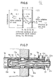
- one end of the second partition means 7 is entirely connected to the support means 10, while its other end is also entirely connected to a lid 12 which is removably attached to a flange 11 connected to the right-hand end (in Fig. 2) of the tubular body 4.
- the air-permeable solid matter as the partitions 6 and 7 may be heat-resistant material such as metal or ceramics.
- the partitions 6 and 7 each may be of any suitable air-permeable construction other than wire netting, such as honeycomblike shape, fibrous or porous structure having a suitable thickness. It may be considered that the air-permeable solid body is equivalent, in construction, to a number of small-sized spheral objects or wires united in one body; that is, the air-permeable solid body has a very large area of occupied surface (i.e., one that is not vacant), so that when gases are allowed to pass through the solid body, the transference of heat by convection is made at a greater rate.
- Numeral 13 designates a means for supporting the second partition 7 at its intermediate portion, which means 13 comprises a band 14 attached to the outer circumference of the second partition 7 and a plurality of legs 15 projecting from the band 14.
- the support plate 9, support means 10 and 13 are all disposed in the tubular body 4 in such a manner that they are allowed to move along the length of the body 4.
- Numeral 16 designates a circular heat-resistant protector connected to the front face of the support plate 9. As clearly shown in Fig. 2, the front face of the support means 10 (i.e., one that is nearer to the burner 27) is flush with the inner surface of the right-hand furnace wall 2.
- Numeral 17 designates a heat-exchange chamber defined by the support plate 9, first and second partitions 6 and 7, and lid 12.
- This chamber 17 includes a bayonet exchanger 18 for preheating air to be used for combustion of the fuel, which exchanger 18 is of a double-tube construction including an outer one 19 and an inner one 20.
- the outer tube 19 is connected to and supported by the lid 12. Also the outer tube 19 is provided with an inlet 21 to allow air from an air blower (not shown) to come into the tube 19.
- the inner tube 20 is provided with an outlet 22 to discharge the air preheated by the exchanger 18, which outlet 22 is connected to the burner 27 by means of a supply pipe (not shown).
- the inner tube 20 is supported by a spiral support or fins 23 which are provided between the two tubes 20 and 19 and are so designed as to allow the maximum contact of the air from the inlet 21 with the outer tube 19.
- the partition 6 is heated to a higher temperature at its outer side than at its inner side.
- the partition 6 thus increased in temperature radiates heat so that the radiator section 4a of the body 4, particularly that portion of the same section surrounding the partition 6, is given an increased temperature, providing a further heat radiation for the material.
- the gases have thus passed the partition 6, they are reduced in temperature by 200°C to 400°C and take their way through the heat-exchange chamber 17 while heating the heat exchanger 18 primarily by the transference of heat by convection.
- the gases then come from the chamber 17 through the second partition 7, heating the same partition in the same manner as when passing the first one 6 so that they are further reduced in temperature by 100°C to 300°C to have a temperature of approximately 400°C when coming out from the outlet 5.
- the outer tube 19 of the heat exchanger 18 is heated not only by the hot gases flowing into the chamber 17 while transferring heat by convection, but also by both partitions 6 and 7 radiating heat, so that the air for use in the combustion of fuel is sufficiently preheated in the exchanger 18 for supply to the burner 27.
- the air supplied into the outer tube 19 from the inlet 21 for preheating has a very low temperature compared with the hot gases flowing outside the tube 19; therefore, when the air is preheated by the gases (heating the tube 19), a great amount of thermal energy is given to the air with a higher rate of heat recovery.
- partitions 6 and 7 may be united in one body with the support means 10 connected to its outer circumference.
- the air-permeable solid matter S has the thickness X in the direction of gas flow, and has a temperature gradient indicated by a curved line 24 in its thickness when the hot gases have been allowed to pass the solid matter while transferring its heat thereto by convection.
- different sections X 1 to X 5 along the thickness X radiate thermal energies Y1 to Y5 and Z 1 to Z 5 , respectively, which energies y 1 to Y 5 are to come from the solid matter to the upstream side (Y) of the gas flow, -while those Z 1 to Z 5 to come therefrom to the downstream side (Z) thereof; however, those Z1, Z 2 , Y 4 , and Y 5 of the radiant energies must travel the entire thickness X or a greater part thereof in order to come out from the solid matter, and in such a process these radiant energies are attenuated by the solid matter itself before coming therefrom.
- the major amount of the whole radiant energies therefore, comes to the upstream side (Y) of the gas flow as indicated by numeral 25 (Fig. 6), so that such energies are effectively used for heating the radiator section 4a of the tubular body 4 in particular when they have been radiated from the first partition 6, while such energies are also effectively used for heating the heat-exchanger 18 in particular when they have been radiated from the second partition 7.
- the air-permeable solid mat - ter S for all practical purposes prevents the lowered temperature on the downstream side (Z) from having any thermal effect on the atmosphere on the upstream side (Y); therefore, according to the invention, the heat exchanger 17 located on the downstream side of the gas flow inside the first partition 6 may take away a certain amont of heat from the hot gases without affecting the temperature of that portion of the tubular body 4 located on the upstream side of the first partition 6 in any substantial ways, that is, without practically cooling the same portion of the body 4.
- another embodiment of the radiant tube construction may be such that a first partition means 6e is supported by a support means 13e (similar to the preceding one 13) and an air-permeable flange 34 and closed by an air-permeable plate 33 at its forward end and that a second partition means 7e is also supported by an air-permeable flange 36 at its one end.
- a heat exchanger 31 may be of such a construction that the inside of a tubular body 32 is divided by a horizontal partition means 37 into upper and lower halves, except for the forward end thereof. In such a construction of heat exchanger, air to be heated therein is supplied into the lower space and heated therein to have a reduced weight, and then takes its way very smoothly through the upper space to come out from the exchanger.
- portions or sections identical or similar to those of the first embodiment of Figs. 1 to 5 in function are designated by the same numerals as the preceding portions and the alphabetical letter e attached thereto.
- each heat exchanger is to preheat the air to be used for the combustion of fuel; however, the exchanger may be employed for heating the atmosphere in the furnace or other various fluids.
- the invention has been described as being applied to the radiant tube for heating furnace employing combustion gases produced by the burner as high-temperature gas; however, in addition, the invention may be applied to radiant tubes for a wide variety of uses and constructions which employ various high-temperature gases such as those for use in a salt bath or hothouse.
Abstract
Description
- This invention relates to radiant tubes for use in heating various materials such as steel pieces, other kinds of solid matters, or fluids in a heating furnace.
- In the conventional radiant tube, when high-temperature gases produced by a burner are supplied into the tubular radiator section from one end thereof, the radiator section is increased in its temperature to radiate heat. The gases thus used for heating the radiator are then discharged from the'other end thereof.
- When thus flowing out of the radiator, the gases still have a higher temperature; accordingly, in the past, the inventors herein made an attempt to recover heat from the exhaust gases by locating a heat exchanger within the radiator in a position nearer to its exhaust and. Such a heat exchanger, however, is of a lower temperature so that it may reduce the temperature of its surroundings. Such a lowering of the temperature of the radiator prevents the satisfactory heat radiation for heating the materials.
- An object of the invention is to provide a radiant tube including a heat exchanger located so as to stretch over both radiator section and outflow section of the tube for the purpose of recovering heat from hot combustion gases used for heating the radiator section when the gases flow from the radiator section to the outflow section.
- Another object of the invention is to provide a radiant tube of such a construction that a heat exchanger projecting into a radiator section has no thermal or cooling effect on the radiator section, but the same section is increased in its temperature not only by the direct heating by the flow of hot combustion gases, but by a unique feature.
- That is, according to the invention, a tubular partition means of air-permeable solid matter is disposed between the cylindrical wall of the radiator section and the projecting or forward end of the heat exchanger so that the hot gases having heated the radiator section pass the partition means to come thereinto. At this time a certain amount of heat is given to the partition means by the gases, with the outer side of the same means being increased to a higher temperature so as to radiate a great amount of heat so that the radiator section, enclosing the partition means, is further increased in its temperature. And, in turn, the radiator section supplys a greater amount of heat radiation for the more effective heating of materials. Also the air-permeable partition, enclosing the projecting end of the heat exchanger, provides a means for preventing the heat exchanger, namely, an object of lower temperature, from depriving the radiator section of its heat so that the exchanger can have no cooling effect on the same section.
- A still another object of the invention is to provide a radiant tube which makes it possible to recover a further amount of heat of the hot gases by the heat exchanger at a greater rate after the gases have passed the foregoing partition means.
- That is, according to the invention, not only the foregoing partition means is provided in the manner mentioned, but another tubular partition means of air-permeable solid matter is so disposed as to enclose that portion of the heat exchanger located inside the outflow section so that the hot gases having passed the first partition means and entered thereinto must also enter and pass the second partition means in order to come out from the radiant tube. When passing the second partition means, the gases further transfer its heat to the same partition means so that this means is increased to a higher temperature at its inner side than at its outer side, unlike in the first partition means, because of the heat- radiation properties of the air-permeable solid matter. Therefore, the heat exchanger is heated not only by the hot gases flowing through the space defined by the two partition means, but by the second partition means supplying an inward radiation of no small amount of heat. The recovery of heat-by the heat exchanger is thus made very effectively.
- Other objects and advantages.of the invention will become apparent during the following discussion of the accompanying drawings.
-
- Fig. 1 is a vertical cross section of a forward portion of a first embodiment of radiant tube according to the invention.
- Fig. 2 is a vertical cross section of the remaining portion of the radiant tube of Fig. 1.
- Fig. 3 is a cross section taken on the line III-III of Fig. 2.
- Fig. 4 is also a cross section taken on the line IV-IV of Fig. 2.
- Fig. 5 is also a cross section taken on the line V-V of Fig. 2.
- Fig. 6 is a graphic illustration of how an air-permeable solid matter as the material of parition means radiates heat given by hot combustion gases passing the same solid matter.
- Fig. 7 is a similar view to Fig. 2, showing a second embodiment of radiant tube according to the invention.
- Referring to Figs. 1 to 5, a
radiant tube 3 is so located as to extend throughopposite walls 2 of a heating furnace including aheating chamber 1. Theradiant tube 3 includes atubular body 4 comprising aradiator section 4a located inside theheating chamber 1, an inflow section 4b connected to theradiator section 4a at its one end and projecting outward from one of thefurnace walls 2 at its other end, and an outflow section 4c connected to theradiator section 4a at its one end on the opposite side of the inflow section 4c and projecting outward from the other or opposite furnace wall 2 i at its other end. The inflow section 4b includes aburner 27 provided with'a fuel-supply port 27a and an air-supply port 27b so that a supply of fuel from theport 27a is burned with the help of a supply of air from theport 27b, producing hot combustion gases to be supplied into thetube 3 so as to heat theradiator section 4a. The outflow section 4c has an outlet 5 for allowing the gases used for heating theradiator section 4a to discharge from thetube 3. Inside thetube 3 are disposed a first partition means 6 and a second partition means 7 which both are constructed of air-permeable solid matter into the shape of a tube. In the embodiment herein thepartitions first partition 6 is entirely connected to acircular support plate 9 which is constructed of material not permeable to air, but provided with a number of air holes 8 at its circumference. The other end of thesame partition 6 is also entirely connected to an annular heat-resistant support means 10 constructed of material not permeable to air. Also, one end of the second partition means 7 is entirely connected to the support means 10, while its other end is also entirely connected to alid 12 which is removably attached to aflange 11 connected to the right-hand end (in Fig. 2) of thetubular body 4. The air-permeable solid matter as thepartitions partitions second partition 7 at its intermediate portion, which means 13 comprises aband 14 attached to the outer circumference of thesecond partition 7 and a plurality oflegs 15 projecting from theband 14. Thesupport plate 9, support means 10 and 13 are all disposed in thetubular body 4 in such a manner that they are allowed to move along the length of thebody 4. Numeral 16 designates a circular heat-resistant protector connected to the front face of thesupport plate 9. As clearly shown in Fig. 2, the front face of the support means 10 (i.e., one that is nearer to the burner 27) is flush with the inner surface of the right-hand furnace wall 2. Also, the outer circumference of thefirst partition 6 is directly faced with the inner surface of that portion of thetubular body 4 forming theradiator section 4a. Numeral 17 designates a heat-exchange chamber defined by thesupport plate 9, first andsecond partitions lid 12. Thischamber 17 includes abayonet exchanger 18 for preheating air to be used for combustion of the fuel, which exchanger 18 is of a double-tube construction including an outer one 19 and an inner one 20. Theouter tube 19 is connected to and supported by thelid 12. Also theouter tube 19 is provided with aninlet 21 to allow air from an air blower (not shown) to come into thetube 19. Theinner tube 20 is provided with anoutlet 22 to discharge the air preheated by theexchanger 18, whichoutlet 22 is connected to theburner 27 by means of a supply pipe (not shown). Theinner tube 20 is supported by a spiral support orfins 23 which are provided between the twotubes inlet 21 with theouter tube 19. - In the radiant 'tube 3 with the foregoing construction, when fuel is burned by the
burner 27, hot combustion gases with a temperature of approximately 1,100°C are produced and allowed to flow into thetube 3 so as to heat thetubular body 4 primarily by the transference of heat by convection, so that thebody 4 heated radiates heat. In this process theradiator section 4a of the body 4 (located inside the heating chamber 1) heats the material supplied into thechamber 1 for treatment, as is well known. The gases then come from the space betweenbody 4 andfirst partition 6 into the heat-exchange chamber 17.- At this time, i.e., when the gases pass thepartition 6, the same partition is heated thereby up to a temperature close'to that of the gases as thepartition 6 has a very large area of occupied surface as mentioned before. And thepartition 6 is heated to a higher temperature at its outer side than at its inner side. Thepartition 6 thus increased in temperature radiates heat so that theradiator section 4a of thebody 4, particularly that portion of the same section surrounding thepartition 6, is given an increased temperature, providing a further heat radiation for the material. When the gases have thus passed thepartition 6, they are reduced in temperature by 200°C to 400°C and take their way through the heat-exchange chamber 17 while heating theheat exchanger 18 primarily by the transference of heat by convection. The gases then come from thechamber 17 through thesecond partition 7, heating the same partition in the same manner as when passing the first one 6 so that they are further reduced in temperature by 100°C to 300°C to have a temperature of approximately 400°C when coming out from the outlet 5. In such a process theouter tube 19 of theheat exchanger 18 is heated not only by the hot gases flowing into thechamber 17 while transferring heat by convection, but also by bothpartitions exchanger 18 for supply to theburner 27. - The air supplied into the
outer tube 19 from theinlet 21 for preheating has a very low temperature compared with the hot gases flowing outside thetube 19; therefore, when the air is preheated by the gases (heating the tube 19), a great amount of thermal energy is given to the air with a higher rate of heat recovery. - Although not shown in the drawings, the
partitions - Referring to Fig. 6, a description will be made of how the air-permeable solid matter as the material of
partitions curved line 24 in its thickness when the hot gases have been allowed to pass the solid matter while transferring its heat thereto by convection. And different sections X1 to X5 along the thickness X radiate thermal energies Y1 to Y5 and Z1 to Z 5 , respectively, which energies y 1 to Y5 are to come from the solid matter to the upstream side (Y) of the gas flow, -while those Z1 to Z5 to come therefrom to the downstream side (Z) thereof; however, those Z1, Z 2, Y4 , and Y5 of the radiant energies must travel the entire thickness X or a greater part thereof in order to come out from the solid matter, and in such a process these radiant energies are attenuated by the solid matter itself before coming therefrom. The major amount of the whole radiant energies, therefore, comes to the upstream side (Y) of the gas flow as indicated by numeral 25 (Fig. 6), so that such energies are effectively used for heating theradiator section 4a of thetubular body 4 in particular when they have been radiated from thefirst partition 6, while such energies are also effectively used for heating the heat-exchanger 18 in particular when they have been radiated from thesecond partition 7. Also it has been found that if any amount of heat existing on the downstream side (Z) of the gas flow is removed therefrom, the air-permeable solid mat- ter S for all practical purposes prevents the lowered temperature on the downstream side (Z) from having any thermal effect on the atmosphere on the upstream side (Y); therefore, according to the invention, theheat exchanger 17 located on the downstream side of the gas flow inside thefirst partition 6 may take away a certain amont of heat from the hot gases without affecting the temperature of that portion of thetubular body 4 located on the upstream side of thefirst partition 6 in any substantial ways, that is, without practically cooling the same portion of thebody 4. - Referring to Fig. 7, another embodiment of the radiant tube construction may be such that a first partition means 6e is supported by a support means 13e (similar to the preceding one 13) and an air-
permeable flange 34 and closed by an air-permeable plate 33 at its forward end and that a second partition means 7e is also supported by an air-permeable flange 36 at its one end. Also, in this embodiment, aheat exchanger 31 may be of such a construction that the inside of atubular body 32 is divided by a horizontal partition means 37 into upper and lower halves, except for the forward end thereof. In such a construction of heat exchanger, air to be heated therein is supplied into the lower space and heated therein to have a reduced weight, and then takes its way very smoothly through the upper space to come out from the exchanger. - In the second embodiment, portions or sections identical or similar to those of the first embodiment of Figs. 1 to 5 in function are designated by the same numerals as the preceding portions and the alphabetical letter e attached thereto.
- In the foregoing two embodiments, the purpose of each heat exchanger is to preheat the air to be used for the combustion of fuel; however, the exchanger may be employed for heating the atmosphere in the furnace or other various fluids.
- Also, the invention has been described as being applied to the radiant tube for heating furnace employing combustion gases produced by the burner as high-temperature gas; however, in addition, the invention may be applied to radiant tubes for a wide variety of uses and constructions which employ various high-temperature gases such as those for use in a salt bath or hothouse.
Claims (4)
Applications Claiming Priority (2)
| Application Number | Priority Date | Filing Date | Title |
|---|---|---|---|
| JP56116877A JPS5818015A (en) | 1981-07-24 | 1981-07-24 | Radiant tube |
| JP116877/81 | 1981-07-24 |
Publications (3)
| Publication Number | Publication Date |
|---|---|
| EP0071073A2 true EP0071073A2 (en) | 1983-02-09 |
| EP0071073A3 EP0071073A3 (en) | 1983-11-09 |
| EP0071073B1 EP0071073B1 (en) | 1985-11-13 |
Family
ID=14697840
Family Applications (1)
| Application Number | Title | Priority Date | Filing Date |
|---|---|---|---|
| EP82106271A Expired EP0071073B1 (en) | 1981-07-24 | 1982-07-13 | Radiant tube |
Country Status (4)
| Country | Link |
|---|---|
| US (1) | US4479535A (en) |
| EP (1) | EP0071073B1 (en) |
| JP (1) | JPS5818015A (en) |
| DE (1) | DE3267414D1 (en) |
Cited By (5)
| Publication number | Priority date | Publication date | Assignee | Title |
|---|---|---|---|---|
| FR2595791A1 (en) * | 1986-03-14 | 1987-09-18 | Centre Nat Rech Scient | BURNER WITH LOW GAS EMISSION POLLUTANTS |
| EP0403063A2 (en) * | 1989-06-14 | 1990-12-19 | Wellman Furnaces Limited | Radiant tube |
| EP0826926A3 (en) * | 1996-08-30 | 1999-04-21 | Bloom Engineering Company, Inc. | Recuperative radiant tube with hot side vitiation |
| WO2012163513A1 (en) | 2011-05-31 | 2012-12-06 | Latecoere | Emergency opening device for an aircraft door |
| WO2021005021A1 (en) | 2019-07-08 | 2021-01-14 | Latecoere | Emergency opening device of an aircraft door having a retention wire |
Families Citing this family (21)
| Publication number | Priority date | Publication date | Assignee | Title |
|---|---|---|---|---|
| DE3323781C2 (en) * | 1983-07-01 | 1986-04-03 | Uhde Gmbh, 4600 Dortmund | Device for cooling thick-walled, horizontally arranged tube sheets of heat exchangers |
| JPS61110875A (en) * | 1984-11-01 | 1986-05-29 | 三菱油化エンジニアリング株式会社 | Radiant heater |
| JPH064171Y2 (en) * | 1987-05-01 | 1994-02-02 | 大同特殊鋼株式会社 | Radiant chives |
| US5269133A (en) * | 1991-06-18 | 1993-12-14 | General Electric Company | Heat exchanger for cooling a gas turbine |
| US5542467A (en) * | 1993-07-06 | 1996-08-06 | Societe E'etudes Et De Constructions Aero-Navales | Safety annular heat exchanger for incompatible fluids |
| US6029647A (en) * | 1996-08-30 | 2000-02-29 | Bloom Engineering Company, Inc. | Recuperative radiant tube with hot side vitiation |
| US6019598A (en) * | 1998-07-06 | 2000-02-01 | Dana Corporation | Air recuperator for combustion air burners |
| US6321743B1 (en) | 2000-06-29 | 2001-11-27 | Institute Of Gas Technology | Single-ended self-recuperated radiant tube annulus system |
| US7299643B2 (en) * | 2004-09-29 | 2007-11-27 | Chevron U.S.A. Inc. | Method for recovering LPG boil off gas using LNG as a heat transfer medium |
| US8162040B2 (en) * | 2006-03-10 | 2012-04-24 | Spinworks, LLC | Heat exchanging insert and method for fabricating same |
| KR100741162B1 (en) * | 2006-09-07 | 2007-07-20 | 주식회사 대일냉각기 | Heat-exchanger for a cooler |
| JP5300725B2 (en) * | 2006-09-18 | 2013-09-25 | ストーム ディヴェロップメント エルエルシー | Radiant heat transfer system |
| US7654257B2 (en) * | 2007-05-18 | 2010-02-02 | John Vancak | Radiant heater assembly |
| US8105076B2 (en) | 2007-08-06 | 2012-01-31 | Thomas & Betts International, Inc. | High efficiency radiant heater |
| EP2215404A1 (en) * | 2007-09-21 | 2010-08-11 | Wessex Incorporated | Radiant tube |
| JP5767020B2 (en) * | 2011-05-25 | 2015-08-19 | Jfeスチール株式会社 | Air preheater |
| JP5965170B2 (en) * | 2012-03-19 | 2016-08-03 | 新和企業株式会社 | Radiant tube heating device |
| US9976740B2 (en) * | 2012-06-12 | 2018-05-22 | Board of Regents of the Nevada Systems of Higher Educations, on Behalf of the University of Nevada, Reno | Burner |
| JP6044508B2 (en) * | 2013-10-28 | 2016-12-14 | Jfeスチール株式会社 | Radiant tube heating device |
| US10458646B2 (en) * | 2014-09-25 | 2019-10-29 | Selas Heat Technology Company Llc | Low NOx, high efficiency, high temperature, staged recirculating burner and radiant tube combustion system |
| US9631808B2 (en) * | 2014-11-21 | 2017-04-25 | Honeywell International Inc. | Fuel-air-flue gas burner |
Citations (5)
| Publication number | Priority date | Publication date | Assignee | Title |
|---|---|---|---|---|
| NL75988C (en) * | 1900-01-01 | |||
| GB980472A (en) * | 1962-08-29 | 1965-01-13 | Bloom Eng Co Inc | Recuperative radiant tube burner mechanism |
| GB1376303A (en) * | 1972-05-03 | 1974-12-04 | Atomic Energy Authority Uk | Tubular heat exchangers |
| US3908628A (en) * | 1973-10-16 | 1975-09-30 | Thermo Electron Corp | Jet impingement recuperator |
| US3920383A (en) * | 1974-06-20 | 1975-11-18 | Electric Furnace Co | Fluted surface heat exchanger |
Family Cites Families (9)
| Publication number | Priority date | Publication date | Assignee | Title |
|---|---|---|---|---|
| CH108792A (en) * | 1924-03-11 | 1925-04-01 | Philipp Otto | Element for heat exchangers. |
| FR997750A (en) * | 1948-10-21 | 1952-01-09 | Handelsgesellschaft Der Furstl | Pyrogenation oven |
| GB907504A (en) * | 1961-01-13 | 1962-10-03 | Nassheuer Jean | Improvements in combustion radiant heaters |
| SU463725A1 (en) * | 1972-01-11 | 1975-03-15 | Институт черной металлургии | Deadlock radiation tube |
| US3946719A (en) * | 1974-07-31 | 1976-03-30 | Semen Efimovich Bark | Radiant gas heater |
| US4111258A (en) * | 1976-05-10 | 1978-09-05 | Exxon Production Research Company | Split air convection pile |
| GB2041181B (en) * | 1978-12-29 | 1983-08-17 | Hutni Druhovyroba | Flameless combustion method and a boiler utilizing such method |
| DE3017574C2 (en) * | 1980-05-08 | 1985-06-05 | Wieland-Werke Ag, 7900 Ulm | Spacers for coaxial heat exchangers |
| US4310303A (en) * | 1980-07-11 | 1982-01-12 | W. B. Combustion, Inc. | Plug-in recuperator and method |
-
1981
- 1981-07-24 JP JP56116877A patent/JPS5818015A/en active Granted
-
1982
- 1982-07-13 DE DE8282106271T patent/DE3267414D1/en not_active Expired
- 1982-07-13 EP EP82106271A patent/EP0071073B1/en not_active Expired
- 1982-07-21 US US06/400,325 patent/US4479535A/en not_active Expired - Fee Related
Patent Citations (5)
| Publication number | Priority date | Publication date | Assignee | Title |
|---|---|---|---|---|
| NL75988C (en) * | 1900-01-01 | |||
| GB980472A (en) * | 1962-08-29 | 1965-01-13 | Bloom Eng Co Inc | Recuperative radiant tube burner mechanism |
| GB1376303A (en) * | 1972-05-03 | 1974-12-04 | Atomic Energy Authority Uk | Tubular heat exchangers |
| US3908628A (en) * | 1973-10-16 | 1975-09-30 | Thermo Electron Corp | Jet impingement recuperator |
| US3920383A (en) * | 1974-06-20 | 1975-11-18 | Electric Furnace Co | Fluted surface heat exchanger |
Cited By (9)
| Publication number | Priority date | Publication date | Assignee | Title |
|---|---|---|---|---|
| FR2595791A1 (en) * | 1986-03-14 | 1987-09-18 | Centre Nat Rech Scient | BURNER WITH LOW GAS EMISSION POLLUTANTS |
| EP0242249A1 (en) * | 1986-03-14 | 1987-10-21 | Centre National De La Recherche Scientifique (Cnrs) | Burner with low polluting-gas emission |
| US4790744A (en) * | 1986-03-14 | 1988-12-13 | Centre National De La Recherche Scientifique | Burner with low emission of polluting gases |
| EP0403063A2 (en) * | 1989-06-14 | 1990-12-19 | Wellman Furnaces Limited | Radiant tube |
| EP0403063A3 (en) * | 1989-06-14 | 1991-02-06 | Wellman Furnaces Limited | Radiant tube |
| EP0826926A3 (en) * | 1996-08-30 | 1999-04-21 | Bloom Engineering Company, Inc. | Recuperative radiant tube with hot side vitiation |
| WO2012163513A1 (en) | 2011-05-31 | 2012-12-06 | Latecoere | Emergency opening device for an aircraft door |
| WO2021005021A1 (en) | 2019-07-08 | 2021-01-14 | Latecoere | Emergency opening device of an aircraft door having a retention wire |
| FR3098490A1 (en) | 2019-07-08 | 2021-01-15 | Latecoere | Emergency opening device for an aircraft door with a retaining wire |
Also Published As
| Publication number | Publication date |
|---|---|
| EP0071073B1 (en) | 1985-11-13 |
| JPS5818015A (en) | 1983-02-02 |
| DE3267414D1 (en) | 1985-12-19 |
| US4479535A (en) | 1984-10-30 |
| JPS6235013B2 (en) | 1987-07-30 |
| EP0071073A3 (en) | 1983-11-09 |
Similar Documents
| Publication | Publication Date | Title |
|---|---|---|
| US4479535A (en) | Recuperative radiant tube | |
| RU2208741C2 (en) | Unit heater | |
| US2276527A (en) | Apparatus for heating fluids | |
| JP2986982B2 (en) | Small gas fired air heater | |
| JPH0159520B2 (en) | ||
| US5224539A (en) | Cooling system for air heaters and the like | |
| JPS59113117A (en) | Continuous heating furnace | |
| CN105890159B (en) | The hot water circuit structure of built-in communicating pipe and multipath circulating fluidized bed hot-water boiler | |
| TWM332800U (en) | An instantaneous heat superconducting tube boiler | |
| JPS63163792A (en) | Waste heat recovery apparatus for radiating pipe | |
| CN211570736U (en) | Energy-saving billet heating furnace | |
| RU2168121C1 (en) | Process heater | |
| GB2077899A (en) | Heater for a process fluid | |
| JPS6135340Y2 (en) | ||
| US3313286A (en) | Heat exchange apparatus | |
| KR950008564Y1 (en) | Boiler | |
| JPH0739880B2 (en) | Fluid heating device | |
| JPS631491B2 (en) | ||
| JPS624832Y2 (en) | ||
| JP2958263B2 (en) | High temperature regenerator | |
| KR940008441B1 (en) | Heat exchanger constructing porous | |
| US3121420A (en) | Heater with vertically extended tubes in convection section | |
| RU27194U1 (en) | GAS HEATER | |
| JPS63163791A (en) | Waste heat recovery apparatus for radiating pipe | |
| KR200432038Y1 (en) | Boiler of heat fin |
Legal Events
| Date | Code | Title | Description |
|---|---|---|---|
| PUAI | Public reference made under article 153(3) epc to a published international application that has entered the european phase |
Free format text: ORIGINAL CODE: 0009012 |
|
| AK | Designated contracting states |
Designated state(s): DE FR GB |
|
| PUAL | Search report despatched |
Free format text: ORIGINAL CODE: 0009013 |
|
| AK | Designated contracting states |
Designated state(s): DE FR GB |
|
| 17P | Request for examination filed |
Effective date: 19831125 |
|
| GRAA | (expected) grant |
Free format text: ORIGINAL CODE: 0009210 |
|
| AK | Designated contracting states |
Designated state(s): DE FR GB |
|
| REF | Corresponds to: |
Ref document number: 3267414 Country of ref document: DE Date of ref document: 19851219 |
|
| ET | Fr: translation filed | ||
| PLBE | No opposition filed within time limit |
Free format text: ORIGINAL CODE: 0009261 |
|
| STAA | Information on the status of an ep patent application or granted ep patent |
Free format text: STATUS: NO OPPOSITION FILED WITHIN TIME LIMIT |
|
| 26N | No opposition filed | ||
| PGFP | Annual fee paid to national office [announced via postgrant information from national office to epo] |
Ref country code: GB Payment date: 19940705 Year of fee payment: 13 |
|
| PGFP | Annual fee paid to national office [announced via postgrant information from national office to epo] |
Ref country code: DE Payment date: 19940708 Year of fee payment: 13 |
|
| PGFP | Annual fee paid to national office [announced via postgrant information from national office to epo] |
Ref country code: FR Payment date: 19940711 Year of fee payment: 13 |
|
| PG25 | Lapsed in a contracting state [announced via postgrant information from national office to epo] |
Ref country code: GB Effective date: 19950713 |
|
| GBPC | Gb: european patent ceased through non-payment of renewal fee |
Effective date: 19950713 |
|
| PG25 | Lapsed in a contracting state [announced via postgrant information from national office to epo] |
Ref country code: DE Effective date: 19960402 |
|
| PG25 | Lapsed in a contracting state [announced via postgrant information from national office to epo] |
Ref country code: FR Effective date: 19960430 |
|
| REG | Reference to a national code |
Ref country code: FR Ref legal event code: ST |
|
| REG | Reference to a national code |
Ref country code: FR Ref legal event code: ST |
|
| REG | Reference to a national code |
Ref country code: FR Ref legal event code: ST |