EP0070187A2 - Apparatus for finishing synthetic polymers - Google Patents
Apparatus for finishing synthetic polymers Download PDFInfo
- Publication number
- EP0070187A2 EP0070187A2 EP82303670A EP82303670A EP0070187A2 EP 0070187 A2 EP0070187 A2 EP 0070187A2 EP 82303670 A EP82303670 A EP 82303670A EP 82303670 A EP82303670 A EP 82303670A EP 0070187 A2 EP0070187 A2 EP 0070187A2
- Authority
- EP
- European Patent Office
- Prior art keywords
- screw elements
- vessel
- opening
- vent opening
- interior surface
- Prior art date
- Legal status (The legal status is an assumption and is not a legal conclusion. Google has not performed a legal analysis and makes no representation as to the accuracy of the status listed.)
- Granted
Links
Images

Classifications
-
- B—PERFORMING OPERATIONS; TRANSPORTING
- B01—PHYSICAL OR CHEMICAL PROCESSES OR APPARATUS IN GENERAL
- B01F—MIXING, e.g. DISSOLVING, EMULSIFYING OR DISPERSING
- B01F27/00—Mixers with rotary stirring devices in fixed receptacles; Kneaders
- B01F27/80—Mixers with rotary stirring devices in fixed receptacles; Kneaders with stirrers rotating about a substantially vertical axis
- B01F27/92—Mixers with rotary stirring devices in fixed receptacles; Kneaders with stirrers rotating about a substantially vertical axis with helices or screws
- B01F27/922—Mixers with rotary stirring devices in fixed receptacles; Kneaders with stirrers rotating about a substantially vertical axis with helices or screws with two or more helices, e.g. with intermeshing helices
Definitions
- This invention relates to an apparatus for finishing synthetic polymers, and more particularly, it relates to an apparatus having vertical screw elements which fully wipe the interior surfaces of the finisher apparatus.
- U.S. Patent No. 3,717,330 issued to Pinney discloses a separator-finisher apparatus suitable for use in the production of synthetic condensation polymers such as polyamides and polyesters.
- the apparatus disclosed in the patent includes a vessel having an interior surface throughout its vertical length in the shape of two intersecting conical frustums with parallel and substantially vertical axes, the bases of the frustums being displaced upwards with respect to the apexes, two interengaging helical screw elements rotatably mounted within the vessel which upon co-rotation conform to the interior surface of the vessel such that the screw elements effect a complete wiping of the interior surface of the vessel, and the screw elements interengage each other uninterruptedly along their lengths such that each element effects a complete wiping of an adjacent element.
- the term "wiping” as used herein means relative motion between two elements in close and uniform proximity such that a liquid in the clearance between the elements is subject to high shear.
- thermal degradation and gelation tends to occur in stagnant regions of the processing vessel, such as when generated suspended molten polymer particles (aerosols) deposit on conduit surfaces above the vent opening and drain by gravity to the vent edge where stalactites form and dangle into the process space.
- stalactites which are degraded overage material, periodically break off into the melt pool below and contaminate the process.
- the present invention provides an improvement in the Pinney patent. More particularly, it provides a vent opening of greater radial extent than the path swept by the upper faces of the co-rotating screw elements to permit continuous overlap of the edge of the opening by the upper surface of the co-rotating screw elements to eliminate the stalactites and continuously blend off any material that drains from the conduit above the opening.
- vessel 10 containing a polymer melt 12 is in the shape of two intersecting conical frustums and has an interior wall surface 11.
- Two co-rotating interengaging helical screw elements 14a and 14b are supported on shafts 15a and 15b respectively.
- Top plate 20 has an inner surface 22 and contains a vent opening 24 and a polymer inlet 26. The vent opening 24 is connected to an appropriate condenser system (not shown).
- Each screw element 14A, 14B has a constant radial cross-section dimension in the plane of rotation; the dimension is approximately equal to the center to center distance of the axes of rotation of each screw element.
- Each screw element increases in bottom-to-top diameter of the developed cone of rotation at the same rate as the enclosing cone so that its motion wipes the interior wall surface 11 of the vessel.
- the top surface 16A, 16B of respective screw elements 14A, 14B is flat in the plane of rotation so the screw elements will wipe any portion of the inner surface 22 of top plate 20 that is in its path of rotation.
- the cross-sectional shape of each screw element is in the form of a trilobe and the two elements 14A, 14B wipe each other.
- each top surface 16A, 16B of elements 14A, 14B wipes an annulus 17A, 17B respectively of surface 22 leaving an unwiped center portion 18A, 18B (FIGS. 2A, 2B).
- FIG. 2C Considering the wiping action in normal combination of the top surfaces 16A, 16B of both elements 14A, 14B in FIG. 2C, some of the area of surface 22 is wiped only by one of the two elements, some of the area is doubly wiped by the overlapping action of the top surfaces 16A, 16B and some of the area in the center (designated 19 in FIG.
- the unwiped center area 19 is in the shape of an american football as made up of two, less than semicircular, arcs. Each arc is generated by the innermost point of the top surface (16A, 16B) during most of the open fraction of its rotation, the open fraction being where the element is no longer wiping surface 11 of the vessel and the remainder being the wiping fraction.
- the unwiped football area 19 was cut out and became the vent opening in the prior art apparatus and, as shown, the screw elements do not shear or overlap the edge of the vent opening anywhere. As a consequence, stalactites form at the edge, periodically break off into the melt pool below and contaminate the process.
- vent opening 24 it is required that the top surface 16A, 16B of each element be completely under surface 22 of lid 20 at some point in its rotation. Also it is required that vent opening 24 not extend outward so that the outboard space 21 between the elements becomes exposed.
- the maximum tolerable open area for vent opening 24 is defined as the locus of points of nearest approach of the edges of the top surfaces 16A, 16B of each element, 14A, 14B, to each other. This locus is opening 24.
- the top surfaces of the elements overlap and shear the edge of opening 24 all over. Such action eliminates the formation of stalactites and continuously blends off any material that drains from the vent above the opening 24.
- opening 24' A more readily machined version of opening is shown as opening 24' in FIG. 4. This is called the single overlap racetrack and is readily formed by two semicircles separated by tangents to the semicircles.
Landscapes
- Chemical & Material Sciences (AREA)
- Chemical Kinetics & Catalysis (AREA)
- Processing And Handling Of Plastics And Other Materials For Molding In General (AREA)
- Other Resins Obtained By Reactions Not Involving Carbon-To-Carbon Unsaturated Bonds (AREA)
- Extrusion Moulding Of Plastics Or The Like (AREA)
Abstract
Description
- This invention relates to an apparatus for finishing synthetic polymers, and more particularly, it relates to an apparatus having vertical screw elements which fully wipe the interior surfaces of the finisher apparatus.
- U.S. Patent No. 3,717,330 issued to Pinney discloses a separator-finisher apparatus suitable for use in the production of synthetic condensation polymers such as polyamides and polyesters. The apparatus disclosed in the patent includes a vessel having an interior surface throughout its vertical length in the shape of two intersecting conical frustums with parallel and substantially vertical axes, the bases of the frustums being displaced upwards with respect to the apexes, two interengaging helical screw elements rotatably mounted within the vessel which upon co-rotation conform to the interior surface of the vessel such that the screw elements effect a complete wiping of the interior surface of the vessel, and the screw elements interengage each other uninterruptedly along their lengths such that each element effects a complete wiping of an adjacent element. The term "wiping" as used herein means relative motion between two elements in close and uniform proximity such that a liquid in the clearance between the elements is subject to high shear. The entire disclosure of the Pinney patent is incorporated herein by way of reference.
- When such an apparatus is used for the preparation of polymers, such as poly(hexamethylene adipamide), thermal degradation and gelation tends to occur in stagnant regions of the processing vessel, such as when generated suspended molten polymer particles (aerosols) deposit on conduit surfaces above the vent opening and drain by gravity to the vent edge where stalactites form and dangle into the process space. These stalactites, which are degraded overage material, periodically break off into the melt pool below and contaminate the process.
- The present invention provides an improvement in the Pinney patent. More particularly, it provides a vent opening of greater radial extent than the path swept by the upper faces of the co-rotating screw elements to permit continuous overlap of the edge of the opening by the upper surface of the co-rotating screw elements to eliminate the stalactites and continuously blend off any material that drains from the conduit above the opening.
- Preferred embodiments of the invention will now be described by way of example and with reference to the accompanying drawings in which:-
- FIG. 1 is a vertical sectional view of one embodiment of the apparatus of this invention.
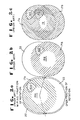
- FIG. 2a, 2b, and 2c are cross-sectional views of a prior art apparatus showing the shape of the vent opening in the top plate and its relationship to the wiping action of the top surface of each helical screw element.
- FIG. 3 is a cross-sectional view of FIG. 1 taken along line 3-3 showing an embodiment of the vent opening of this invention.
- FIG. 4 shows another embodiment of a vent opening of this invention.
- Referring to FIG. 1,
vessel 10 containing apolymer melt 12 is in the shape of two intersecting conical frustums and has an interior wall surface 11. Two co-rotating interengaging helical screw elements 14a and 14b are supported on shafts 15a and 15b respectively.Top plate 20 has aninner surface 22 and contains a vent opening 24 and apolymer inlet 26. Thevent opening 24 is connected to an appropriate condenser system (not shown). - Each
screw element top surface respective screw elements inner surface 22 oftop plate 20 that is in its path of rotation. The cross-sectional shape of each screw element is in the form of a trilobe and the twoelements - Referring now to Prior Art FIGS. 2A, 2B and 2C, and considering only the top surface of each blade rotating in close proximity to the
inner surface 22 oftop plate 20, it can be seen that eachtop surface elements annulus 17A, 17B respectively ofsurface 22 leaving an unwiped center portion 18A, 18B (FIGS. 2A, 2B). Considering the wiping action in normal combination of thetop surfaces elements surface 22 is wiped only by one of the two elements, some of the area is doubly wiped by the overlapping action of thetop surfaces unwiped center area 19 is in the shape of an american football as made up of two, less than semicircular, arcs. Each arc is generated by the innermost point of the top surface (16A, 16B) during most of the open fraction of its rotation, the open fraction being where the element is no longer wiping surface 11 of the vessel and the remainder being the wiping fraction. Theunwiped football area 19 was cut out and became the vent opening in the prior art apparatus and, as shown, the screw elements do not shear or overlap the edge of the vent opening anywhere. As a consequence, stalactites form at the edge, periodically break off into the melt pool below and contaminate the process. - Referring now to FIG. 3 which shows an embodiment of the vent opening 24 of this invention, it is required that the
top surface surface 22 oflid 20 at some point in its rotation. Also it is required that vent opening 24 not extend outward so that theoutboard space 21 between the elements becomes exposed. The maximum tolerable open area forvent opening 24 is defined as the locus of points of nearest approach of the edges of thetop surfaces - A more readily machined version of opening is shown as opening 24' in FIG. 4. This is called the single overlap racetrack and is readily formed by two semicircles separated by tangents to the semicircles.
Claims (5)
Applications Claiming Priority (2)
| Application Number | Priority Date | Filing Date | Title |
|---|---|---|---|
| US06/283,112 US4370061A (en) | 1981-07-13 | 1981-07-13 | Apparatus for finishing synthetic polymers |
| US283112 | 1981-07-13 |
Publications (3)
| Publication Number | Publication Date |
|---|---|
| EP0070187A2 true EP0070187A2 (en) | 1983-01-19 |
| EP0070187A3 EP0070187A3 (en) | 1984-06-06 |
| EP0070187B1 EP0070187B1 (en) | 1987-10-21 |
Family
ID=23084576
Family Applications (1)
| Application Number | Title | Priority Date | Filing Date |
|---|---|---|---|
| EP82303670A Expired EP0070187B1 (en) | 1981-07-13 | 1982-07-13 | Apparatus for finishing synthetic polymers |
Country Status (6)
| Country | Link |
|---|---|
| US (1) | US4370061A (en) |
| EP (1) | EP0070187B1 (en) |
| JP (1) | JPS5823828A (en) |
| AR (1) | AR227470A1 (en) |
| CA (1) | CA1171243A (en) |
| DE (1) | DE3277498D1 (en) |
Families Citing this family (5)
| Publication number | Priority date | Publication date | Assignee | Title |
|---|---|---|---|---|
| US4826323A (en) * | 1988-05-23 | 1989-05-02 | Apv Chemical Machinery Inc. | Self-wiping continuous mixer with enlarged bore section |
| US5411710A (en) * | 1993-06-30 | 1995-05-02 | E. I. Dupont De Nemours And Company | Apparatus for processing materials |
| US5502154A (en) * | 1994-11-30 | 1996-03-26 | E. I. Du Pont De Nemours And Company | Apparatus for processing materials |
| ATE468912T1 (en) * | 2005-04-18 | 2010-06-15 | Gea Pharma Systems Nv | DEVICE FOR CONTINUOUS GRANULATING AND METHOD FOR CONTINUOUS GRANULATING POWDER MATERIAL |
| DE102009024088A1 (en) * | 2009-06-06 | 2010-12-09 | Zeus Gmbh | Tire filler, method for producing a tire filling and apparatus for carrying out the method |
Family Cites Families (8)
| Publication number | Priority date | Publication date | Assignee | Title |
|---|---|---|---|---|
| DE1432024A1 (en) * | 1961-04-18 | 1969-08-07 | Aachener Misch & Knetmasch | Mixer |
| DE1729538B1 (en) * | 1968-01-04 | 1972-02-03 | Werner & Pfleiderer | Continuously working plasticizing machine |
| DE1954864A1 (en) * | 1969-10-31 | 1972-02-10 | Ruberg Bernhard | Mixer/dissolver - with helical ribbon flights |
| GB1315741A (en) * | 1970-06-08 | 1973-05-02 | Du Pont Canada | Mixer |
| DE2446420C2 (en) * | 1974-09-28 | 1982-07-15 | Krauss-Maffei AG, 8000 München | Screw extruder for processing plastics |
| US3995837A (en) * | 1975-07-11 | 1976-12-07 | Fordath Limited | Apparatus for mixing foundry materials |
| US4090261A (en) * | 1977-04-28 | 1978-05-16 | E. I. Du Pont De Nemours And Company | Apparatus for finishing high viscosity synthetic polymers |
| JPS5450592A (en) * | 1977-09-30 | 1979-04-20 | Toray Ind Inc | Preparation of polyester |
-
1981
- 1981-07-13 US US06/283,112 patent/US4370061A/en not_active Expired - Lifetime
-
1982
- 1982-07-08 CA CA000406924A patent/CA1171243A/en not_active Expired
- 1982-07-12 JP JP57120004A patent/JPS5823828A/en active Granted
- 1982-07-13 DE DE8282303670T patent/DE3277498D1/en not_active Expired
- 1982-07-13 EP EP82303670A patent/EP0070187B1/en not_active Expired
- 1982-07-13 AR AR289970A patent/AR227470A1/en active
Also Published As
| Publication number | Publication date |
|---|---|
| EP0070187B1 (en) | 1987-10-21 |
| DE3277498D1 (en) | 1987-11-26 |
| US4370061A (en) | 1983-01-25 |
| JPH0435491B2 (en) | 1992-06-11 |
| EP0070187A3 (en) | 1984-06-06 |
| JPS5823828A (en) | 1983-02-12 |
| AR227470A1 (en) | 1982-10-29 |
| CA1171243A (en) | 1984-07-24 |
Similar Documents
| Publication | Publication Date | Title |
|---|---|---|
| US7708257B2 (en) | Apparatus for treating solids | |
| EP0070707B1 (en) | Apparatus for separating entrained matter from a flowing fluid | |
| US3741104A (en) | Juice extractor with automatic pulp discharge | |
| US4370061A (en) | Apparatus for finishing synthetic polymers | |
| US3934859A (en) | Mixing apparatus | |
| KR100191337B1 (en) | Kneader for mixing materials | |
| JPS62289246A (en) | Mineral separator | |
| JPH0217929A (en) | Stirring apparatus | |
| US5681458A (en) | Water clarification employing rotating drum skimmer | |
| CN201586500U (en) | Slurry fast mixer | |
| US3907537A (en) | Apparatus for producing glass spheres | |
| AU717390B2 (en) | Food processing vat | |
| US2903411A (en) | Wax crystallization process | |
| TW201509515A (en) | Finisher agitator and finisher assembly including the same | |
| JP2001062273A (en) | Continuous mixing device | |
| US4090261A (en) | Apparatus for finishing high viscosity synthetic polymers | |
| JPH09508574A (en) | Centrifuge | |
| JPS58122057A (en) | Method and apparatus for uniformly discharging powder equipped with bridge breaking mechanism | |
| JPS60244313A (en) | Suspension supply apparatus by surface outflow of rotary filter | |
| FI90815B (en) | Containers with dual mixing system, especially shaving containers | |
| JP3133240B2 (en) | Liquid material stirring device and method for producing polycarbonate using the device | |
| US3285416A (en) | Rotary separation of viscous pseudo-plastics | |
| JPS632107Y2 (en) | ||
| JP3808930B2 (en) | Melt forming method and apparatus | |
| JPH0763603B2 (en) | Vertical stirrer |
Legal Events
| Date | Code | Title | Description |
|---|---|---|---|
| PUAI | Public reference made under article 153(3) epc to a published international application that has entered the european phase |
Free format text: ORIGINAL CODE: 0009012 |
|
| AK | Designated contracting states |
Designated state(s): DE FR GB IT |
|
| 17P | Request for examination filed |
Effective date: 19830307 |
|
| PUAL | Search report despatched |
Free format text: ORIGINAL CODE: 0009013 |
|
| AK | Designated contracting states |
Designated state(s): DE FR GB IT |
|
| AK | Designated contracting states |
Designated state(s): DE FR GB IT |
|
| GRAA | (expected) grant |
Free format text: ORIGINAL CODE: 0009210 |
|
| AK | Designated contracting states |
Kind code of ref document: B1 Designated state(s): DE FR GB IT |
|
| ITF | It: translation for a ep patent filed | ||
| REF | Corresponds to: |
Ref document number: 3277498 Country of ref document: DE Date of ref document: 19871126 |
|
| ET | Fr: translation filed | ||
| PLBE | No opposition filed within time limit |
Free format text: ORIGINAL CODE: 0009261 |
|
| STAA | Information on the status of an ep patent application or granted ep patent |
Free format text: STATUS: NO OPPOSITION FILED WITHIN TIME LIMIT |
|
| 26N | No opposition filed | ||
| ITTA | It: last paid annual fee | ||
| PGFP | Annual fee paid to national office [announced via postgrant information from national office to epo] |
Ref country code: FR Payment date: 19960528 Year of fee payment: 15 |
|
| PGFP | Annual fee paid to national office [announced via postgrant information from national office to epo] |
Ref country code: DE Payment date: 19960610 Year of fee payment: 15 |
|
| PGFP | Annual fee paid to national office [announced via postgrant information from national office to epo] |
Ref country code: GB Payment date: 19960620 Year of fee payment: 15 |
|
| PG25 | Lapsed in a contracting state [announced via postgrant information from national office to epo] |
Ref country code: GB Free format text: LAPSE BECAUSE OF NON-PAYMENT OF DUE FEES Effective date: 19970713 |
|
| GBPC | Gb: european patent ceased through non-payment of renewal fee |
Effective date: 19970713 |
|
| PG25 | Lapsed in a contracting state [announced via postgrant information from national office to epo] |
Ref country code: FR Free format text: LAPSE BECAUSE OF NON-PAYMENT OF DUE FEES Effective date: 19980331 |
|
| PG25 | Lapsed in a contracting state [announced via postgrant information from national office to epo] |
Ref country code: DE Free format text: LAPSE BECAUSE OF NON-PAYMENT OF DUE FEES Effective date: 19980401 |
|
| REG | Reference to a national code |
Ref country code: FR Ref legal event code: ST |