EP0070144A1 - Landing legs for vehicle semi-trailer - Google Patents
Landing legs for vehicle semi-trailer Download PDFInfo
- Publication number
- EP0070144A1 EP0070144A1 EP82303558A EP82303558A EP0070144A1 EP 0070144 A1 EP0070144 A1 EP 0070144A1 EP 82303558 A EP82303558 A EP 82303558A EP 82303558 A EP82303558 A EP 82303558A EP 0070144 A1 EP0070144 A1 EP 0070144A1
- Authority
- EP
- European Patent Office
- Prior art keywords
- pump
- liquid
- landing gear
- valve
- cylinder
- Prior art date
- Legal status (The legal status is an assumption and is not a legal conclusion. Google has not performed a legal analysis and makes no representation as to the accuracy of the status listed.)
- Withdrawn
Links
Images


Classifications
-
- B—PERFORMING OPERATIONS; TRANSPORTING
- B60—VEHICLES IN GENERAL
- B60S—SERVICING, CLEANING, REPAIRING, SUPPORTING, LIFTING, OR MANOEUVRING OF VEHICLES, NOT OTHERWISE PROVIDED FOR
- B60S9/00—Ground-engaging vehicle fittings for supporting, lifting, or manoeuvring the vehicle, wholly or in part, e.g. built-in jacks
- B60S9/02—Ground-engaging vehicle fittings for supporting, lifting, or manoeuvring the vehicle, wholly or in part, e.g. built-in jacks for only lifting or supporting
- B60S9/10—Ground-engaging vehicle fittings for supporting, lifting, or manoeuvring the vehicle, wholly or in part, e.g. built-in jacks for only lifting or supporting by fluid pressure
- B60S9/12—Ground-engaging vehicle fittings for supporting, lifting, or manoeuvring the vehicle, wholly or in part, e.g. built-in jacks for only lifting or supporting by fluid pressure of telescopic type
Definitions
- the present invention relates to landing gear for the semi-trailer of an articulated vehicle, that is to say one or more legs at the opposite end to the road- wheels of the trailer and used to support the uncoupled end when detached from the power cab.
- landing gear consisting of two legs which may be raised during road travel and lowered to support the semi-trailer when required. It is customary for these legs to be raised or lowered by a mechanical arrangement and such arrangements are difficult and time consuming to operate. Thus there is often a reluctance on the part of the person operating the legs to move them to their full travel. In particular it is very plausible for the driver merely to raise the legs by only the amount needed to give clearance for normal, smooth roads. It then happens from time to time that the vehicle is driven over a bump in this condition or driven onto a ramp such as a loading ramp leading to a ferry boat and because the legs have not been fully raised they strike the ground and are damaged.
- U.S. Patent 3177664 and U.K Patent 1099599 describe landing gear in which the legs are driven downwardly by hydraulic pressure generated using pneumatic pressure from the vehicle's air brake system.
- a reciprocating pump is used to boost this pressure when required.
- Air pressure is used directly to raise the legs in each case.
- every stroke of the pump must be commanded by movement of a manual control.
- Both of these proposals show a pump, reservoir for hydraulic liquid and control valves connected by pipework in a fairly complicated arrangement.
- French specification 2265588 describes a landing leg operated by fluid pressure (although the type of fluid is not specified). This specification describes a mechanical arrangement for preventing undesired retraction of the leg.
- the present invention seeks to provide an improved arrangement by which one or more legs may be raised or lowered easily and quickly.
- the legs are operated hydraulically, using hydraulic liquid pressurised with another fluid, which is usually compressed air from the vehicle's braking system.
- a reciprocating pump is used to provide an enhanced pressure, at least for part of the downward extension of the legs.
- One aspect of the invention is characterised in that a control valve governing flow of oil to landing gear is incorporated in a common assembly with the pump, preferably without intervening pipework. This gives an economical construction with simpler and more economical assembly, giving apparatus which can more readily be fitted to a semi-trailer.
- the control valve is provided at a valve block which incorporates a chamber of the pump in which hydraulic liquid is pressurised.
- the reciprocating pump includes valve means for causing reciprocation of the pump to repeat automatically.
- a single operation of a manual control enables the landing gear to proceed through its full travel in the upward direction. More preferably there is a single manual control which effects all movements of the landing gear, with respective single operations of this control enabling full movement in either direction.
- a second aspect of this invention is characterised in that the landing gear is fitted with a mechanical locking device to prevent accidental retraction, this locking device being such as to engage automatically on lowering the landing gear and releasable only when the load on the landing gear is not otherwise supported. It is convenient to employ latches or ratchets whose release is prevented except when the load on the legs is supported by hydraulic pressure.
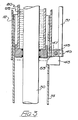
- the landing gear of a semi-trailer comprises a pair of telescopic legs 10, one at each side.
- Each leg has two leg parts 12 and 14, the lower one of which is slidable in the other.
- the lower leg part 14 has wheels 16 at its lower end which contact the road surface when the wheels are in the extended position, so that the semi-trailer is supported on its road wheels and the wheels 16.
- the wheels 16 are also an additional precaution against damage to the lower leg part if this lower leg part 14 should strike an obstruction.
- the upper leg part 12 houses a double acting hydraulic cylinder 20 divided into upper and lower chambers 24,26 by a piston 22.
- a cross member 18 fast with the lower leg part 14 is connected to the piston 22 by a piston rod 30.
- Conduits 134,138 communicate with the upper and lower chambers 24,26. These conduits are led out through the wall of the leg part 12 at its upper end, as shown.
- the cylinder 20 and the conduits 134,138 are arranged so that there is a gap 36 into which the upper portion of the lower leg part 14 is received when the leg 10 is in its retracted position.
- the leg 10 is extended by pumping hydraulic liquid e.g. hydraulic oil, under pressure through conduit 134 into the upper chamber 24 whilst at the same time permitting the fluid from the lower chamber 26 to pass through conduit 138 to a reservoir.
- hydraulic liquid e.g. hydraulic oil
- the conduits 134 of both legs are connected together, and likewise their conduits 138 are connected, so that both legs of the landing gear extend and retract together.
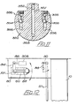
- Each leg is provided with a mechanical locking mechanism, shown in Figs. 2 and 3, which allows extension but blocks retraction until the mechanism is deliberately released.
- the rear face of each lower part contains four pairs of holes 41.
- a pair of latches 43 are pivotally mounted fast with a shaft 45 journalled in brackets 47 on the upper leg part 12.
- a crank 49 on this shaft 45 is pivotally connected to a releasing rod 51.
- the latches 43 have curved faces 53 which allow them to be pushed out as the leg extends. However, the weight of the parts attached to each shaft 45 exerts a turning moment which pushes the latches into the holes 41.
- the legs are normally extended sufficiently to allow the latches to engage holes 41, and then the latches will take the load on the legs, preventing retraction, if the hydraulic pressure is released.
- the latches 43 can be released by an upward pull on the rod 51. The operator may find it necessary to extend the legs very slightly further, first.
- the rods 51 at each side of the trailer are both connected to a single operating handle serving to pull them up together.
- the legs 10 are extended and retracted using hydraulic liquid pressurised with compressed air from the vehicle's braking system.
- a pump 60 shown in Fig. 4 is used to generate a hydraulic liquid pressure in excess of the air pressure, and this is needed at least for the last part of the extension of the legs, when they take the load on the trailer.
- the pump 60 is generally similar to that shown in U.K Patent Specification 1288180.
- the pump is intimate with a valve block which may be either the valve block 100 shown in Figs. 5 to 7, or the block 101 shown in Figs. 9 to 11. In either case the block includes a chamber 130 in which hydraulic liquid is pressurised by the pump.
- the pump 60 has an inlet 200 for compressed air which communicates with a chamber 202, which the air leaves by a bore 204. Compressed air inevitably contains some moisture and this may collect in the line to the pump, resulting in a mass of water suddenly entering the inlet 200.
- the pump can tolerate small amounts of moisture in the compressed air but such a mass of water might damage it, or at least interrupt its operation.
- the chamber 202 prevents any mass of water from passing on into the pump. Instead it collects in the chamber 202 and passes on in small amounts only (by evaporation).
- the pump section has a pump chamber 210, in which is located a piston 212 and a piston rod 214.
- One end of the piston rod 214 is received in the chamber 130 of the valve block whilst the other end is secured to a washer 216.
- a spring 218 extends between an abutment surface 220 of the valve block and the washer 216 to force the piston rod 214 out of the chamber 130 and maintain the washer 216 in contact with the piston 212. The force thus exerted on piston 214 biases it into abutment with surface 222.
- conduit 228 communicates with the high pressure side of the pump chamber 210 so that compressed air passes through conduit 228 into a bore 230.
- Bore 230 contains a valve body 231 having a head 232 and a resilient collar 234 at opposite ends.
- the head 232 normally abuts against a seat 236 thereby sealing bore 230 from pump chamber 210.
- the pressure of the air on the collar 234 forces the valve body 231 to move in the bore 230 towards the piston 212.
- the valve head 232 is lifted from its seat 236 and in doing so it blocks bore 224 so that no more compressed air is delivered to the pump chamber 210 and at the same time establishes communication between the pump chamber and a part of the bore 230 which communicates with the atmosphere through opening 238 and hence the air pressure in the pump chamber 210 is reduced.
- the spring 218 then forces the piston 212 towards surface 222.
- the piston rod 214 moves outwardly from the chamber 130 of the valve block. This is the suction stroke of the pump in which fluid is drawn from a reservoir through valving into the chamber 130.
- Figs. 5 to 7 show a first form of valve block 100 which is used when liquid is drawn from a single reservoir and delivered by the pump to accomplish both the extension and retraction of the legs.
- the valve block is generally cylindrical, and at its end 160 shown by Fig. 6, opposite to the chamber 130, it has a compressed air inlet 126, a compressed air outlet 124 which is connected to the pump inlet 200 by an external pipe (not shown), an opening 128 connected to a reservoir for hydraulic liquid and openings 164, 168 respectively connected to the conduits 134,138 leading to the legs.
- the cylindrical valve block 100 contains six valves 102a to 102f arranged radially around circumference of the valve.
- the valves may, for example, have ball shaped valve members held against a seat by a spring.
- Each of valves 102a to 102e has an associated operating member 104a to 104e which projects outwardly from the valve block 100 to cooperate with an actuating member 106 which is arranged encircling the valve block (Fig. 7).
- the operating members 104a to 104e open the corresponding valve 102a to 102e when depressed.
- the operating member 104a is in the form of a spring loaded plunger in a bore 108a in the valve 102a.
- the end of the bore 108a forms a valve seat 110a against which a ball 112a in a valve chamber l14a is held by a spring 116a.
- the operating member 104a is depressed in the bore 108a against its spring 116a it unseats the ball 112a thereby opening the valve 102a.
- Valves 102d and 102e are similar to valve 102a.
- Valve 102b has the same features as valve 102a but has a second ball 118b at the end of the valve chamber 114b furthest from the first ball 112b which is held by the spring 116b against a seat 120b leading to a bore 122b. High pressure liquid in the bore 122b lifts the ball 118b off its seat 120b but the valve 102b is only open when the ball 112b is also moved off its seat 110b by the operating member 104b.
- valve 102c is similar to valve 102b.
- Valve 102f has no operating member, and has a single ball 112f held against a seat 110f by spring 116f, the ball 112f being lifted off its seat 110f by the suction of liquid into valve chamber 114f but preventing return flow.
- Valve 102a is a valve to control the air supply to the pump, through inlet 126, the bore 122a leading to the valve chamber 114a and hence to the outlet 124.
- Valve 102f is a low pressure liquid inlet valve connected between the liquid reservoir and the pump. On the suction stroke of the pump fluid is drawn through conduit 128 and valve 102f via bore 122f into chamber 130. Valve 102f is a non-return valve so that liquid cannot return to the reservoir on the compression stroke of the pump.
- Valves 102b and 102c govern the delivery of hydraulic liquid under pressure to either the conduits 134 or the conduits 138, and hence to either the upper or lower chambers in the cylinders 20.
- the valves 102d and 102e enable the flow of hydraulic liquid from the chambers which are not pressurised, back to the reservoir.
- the actuating member 106 is an annulus concentric with the block 100. It carries internal projections 148,150 at diametrically opposite positions, and two smaller projections 152. The actuating member 106 can be turned either to open the valves 102b and 102e or the valves 102c and 102d. In either case the air valve 102a is opened.
- valve 102a Operation is as follows. If the actuating member is turned either clockwise or anticlockwise air is passed through the valve 102a, hence to the pump inlet 200.
- the pump pressurises the liquid in chamber 130 on its compression stroke and the pressurised liquid is supplied to both of valves 102b,102c through bores 122b,122c respectively. Only one of these valves can be open. If, for example, the actuating member 106 has been turned anticlockwise, as seen in Fig. 7, to depress operating member 104b and so open valve 102b, the pressurised liquid can flow to conduit 132 hence to opening 164 and into the conduits 134 leading to the upper chambers 24, extending the legs. Valve 102c is closed to prevent pressurised liquid flowing to the lower chambers 26. However, valve 102e is open, allowing liquid from chambers 26 to flow via conduits 138, opening 168, conduit 140, valve 102e, conduit 142 and opening 128 to the reservoir.
- valves 104c and 104d are open.
- Pressurised liquid can flow via conduit 136 to opening 168 leading to conduits 138 and so the lower chambers 26, retracting the legs. Liquid from the upper chambers returns to the reservoir via conduits 134,144, valve 104d and conduit 146.
- the pump 60 supplies all the hydraulic liquid to extend or retract the landing gear.
- a single operation of the actuating member 106 namely turning it one way or the other, enables the landing gear to extend or retract fully.
- Fig. 8 shows schematically a second pump and valve arrangement, which uses the same pump 60 shown in Fig. 4, but a different valve block 101 and two reservoirs 301,302 for hydraulic liquid.
- Each reservoir is a cylinder divided by a piston 303 into respective chambers 305,307 for hydraulic liquid and air.
- Air from the vehicle's braking system is supplied to a three position air valve 308 which can deliver the air either to conduit 311 or to conduit 312, venting the other conduit in each case, or can shut off the air and vent both conduits 311,312.
- the valve 308 can be a sliding spool valve of conventional type.
- conduits 311,312 lead through a block 314 to the air chambers of the reservoirs 301,302.
- Non-return valves 316 in this block provide that air pressure in either conduit 311,312 pressurises conduit 318 leading to the pump's air inlet 200.
- valve block 101 shown in Figs. 9 and 10 is intimate with the pump, and incorporates a chamber 130 in which the hydraulic liquid is pressurised.
- a valve 320 governing the flow of hydraulic liquid is provided on the valve block 101 and is operated simultaneously with the air valve 308.
- the valve 320 has a cylindrical spool 322 (Figs. 10 and 11) rotatable over a flat face 324 on the valve block 101.
- the face 324 includes six ports evenly distributed in a circular array, and the spool 322 also has six ports in its confronting face 326, connected by passages within the spool.
- the spool runs on a bearing 328 sandwiched between the spool and a retaining nut 330.
- Poppets 332 are provided in the ports in the face 324. The hydraulic liquid pressure urges these into sealing contact with the spool's face 326.
- the spool 322 is fast with a shaft 334 by which it is turned.
- the conduits 134 leading to the upper chambers 24 of the landing legs' cylinder 20 are connected through bore 361 to port 341.
- the conduits 138 are connected through bore 362 to port 342.
- the chamber 130 is connected to the ports 344 and 345 by bores 364.
- the liquid chamber of reservoir 301 is connected through bore 366 to port 346 and also connected through bore 367 to a non-return valve 369 connected to the chamber 130.
- the reservoir 302 is connected through bore 363 to port 343, and also connected to chamber 130 through bore 368 and non-return valve 370.
- the spool 322 has a diametral passage 351 between its ports 352,353, and side passages which each contain non-return valves 354,355 and connect adjacent ports 356. In the central position of the spool none of the spool's ports align with ports in the face 324. Consequently there is no flow.
- the air valve 308 is switched to pressurise conduit 311 and reservoir 301.
- Air is delivered to the pump, via one non-return valve 316 and so the pump operates.
- the liquid valve spool 322 is turned 30° clockwise.
- Hydraulic liquid is delivered via bores 366,367 and valve 369 to the chamber 130 during the suction stroke of the pump, then during the pressure stroke it flows from port 344 through the diametral spool passage 351 to the port 341, and hence to the conduits 134 and the legs's upper chambers 24.
- the non-return valves 369,370 prevent the pumping of liquid into either reservoir during the pressure stroke of the pump.
- the lower chambers 26 of the legs are connected to the other reservoir 302, via conduits 138, bore 362 and non-return valve 355 connecting ports 342 and 343.
- This reservoir 302 is vented, so liquid can flow to it from the lower chambers 26. Since there is no hydraulic pressure at all in chambers 26, the air pressure on reservoir 301 can drive liquid directly to the chambers 24, by-passing the pump, as long as the pressure provided by the air above is sufficient to overcome any resistance to movement of the leg. This by-pass flow can proceed from port 346 through non-return valve 354 in the spool to port 345 which is connected to the port 344 via the bores 364.
- valve 369 Since both the non-return valve 369 and the non-return valve 354 deliver to.bores connected to chamber 130 and port 345, some by-pass flow will pass through valve 369, and some flow into the chamber 130 during the pump's suction stroke may pass through valve 354. However, the valves 354 and 369 prevent return to the reservoir 301 at any time.
- valve shown in Figs. 9 to 11 can be made to handle pressures well in excess of 600 bar.
- the valve shown in Figs. 5 to 7 can also be made to handle such pressures, although less conveniently.
- the pump shown in Fig. 4 generates a hydraulic pressure which is greater than the incoming air pressure by a factor which depends on the ratio of the cross-sectional areas of the rod 214 and piston 212.
- These areas are preferably arranged to multiply the pressure more than sixty times, and typically they will multiply it eighty or one hundred times.
- a commercial vehicle's compressed air is normally at about 7 bar.
- the cross-sectional areas are preferably chosen to give a hydraulic liquid pressure in excess of 600 bar, which is considerably more than the usual pressure in vehicle hydraulic systems.
- the flows of hydraulic liquid are basically between reservoir 301 and the legs' upper chambers 24, and between reservoir 302 and the legs' lower chambers 26. Some mixing occurs only because a common pump and oil valve are used. Nevertheless it is conceivable that some net flow from one reservoir to the other could occur, and potentially this could lead to overfilling of one reservoir.
- the valve block 101 includes further connections shown in Fig. 10. Non-return valves 372 have relatively forceful closing springs so that there is normally no flow through them, but if the pressure in either reservoir exceeds a predetermined limit the pressure in the bore 363 or 366 connected to that reservoir is relieved through the associated valve 372 into the associated one of small bores 374 leading to the cavity 376.
- Fig. 12 shows the positioning of the controls on a semi-trailer.
- a plate 80 is mounted below one side of the trailer body just behind one of the legs 10.
- the pump 60 and valve block 101 are mounted behind the plate 80 with a control lever 82 attached to the spool operating shaft 334.
- the air valve is also mounted behind the plate 80, and a crank 84 on the shaft 334 is connected to the air valve 308 by a rod 86, so that when the control lever 82 is turned to turn the spool 322, it also effects the associated operation of the valve 308. Depressing the lever 82 30o from the horizontal is all that is required to effect extension of the legs to their full extent. Release of the latches 43 and raising of the lever 82 is all that is needed to effect full retraction of the legs.
- a second lever 88 is provided to release the latches 43.
- This lever is connected to a pivoted shaft extending across the width of the semi-trailer, and which carries a crank 90 at each side, connected to the rod 51 at that side. Moving the lever 88 forward raises the rods 51 to release the latches.
Abstract
Landing legs 10 forthe semi-trailer of an articulated lorry are operated hydraulically using the vehicle's compressed air to pump hydraulic fluid. In such an arrangement a liquid control valve is provided at a valve block 100,101 intimate with a pump 60 facilitating production and assembly. The pump 60 reciprocates automatically so that one control operation can effect full travel of the legs. Mechanical latches 43 lock the legs 10 and cannot be released under load.
Description
- The present invention relates to landing gear for the semi-trailer of an articulated vehicle, that is to say one or more legs at the opposite end to the road- wheels of the trailer and used to support the uncoupled end when detached from the power cab.
- It is conventional to provide landing gear consisting of two legs which may be raised during road travel and lowered to support the semi-trailer when required. It is customary for these legs to be raised or lowered by a mechanical arrangement and such arrangements are difficult and time consuming to operate. Thus there is often a reluctance on the part of the person operating the legs to move them to their full travel. In particular it is very tempting for the driver merely to raise the legs by only the amount needed to give clearance for normal, smooth roads. It then happens from time to time that the vehicle is driven over a bump in this condition or driven onto a ramp such as a loading ramp leading to a ferry boat and because the legs have not been fully raised they strike the ground and are damaged.
- U.S. Patent 3177664 and U.K Patent 1099599 describe landing gear in which the legs are driven downwardly by hydraulic pressure generated using pneumatic pressure from the vehicle's air brake system. A reciprocating pump is used to boost this pressure when required. Air pressure is used directly to raise the legs in each case. In these proposals every stroke of the pump must be commanded by movement of a manual control. Both of these proposals show a pump, reservoir for hydraulic liquid and control valves connected by pipework in a fairly complicated arrangement.
- French specification 2265588 describes a landing leg operated by fluid pressure (although the type of fluid is not specified). This specification describes a mechanical arrangement for preventing undesired retraction of the leg.
- Despite these prior proposals, it remains normal practice to employ mechanically operated landing legs.
- Broadly, the present invention seeks to provide an improved arrangement by which one or more legs may be raised or lowered easily and quickly. The legs are operated hydraulically, using hydraulic liquid pressurised with another fluid, which is usually compressed air from the vehicle's braking system. A reciprocating pump is used to provide an enhanced pressure, at least for part of the downward extension of the legs. One aspect of the invention is characterised in that a control valve governing flow of oil to landing gear is incorporated in a common assembly with the pump, preferably without intervening pipework. This gives an economical construction with simpler and more economical assembly, giving apparatus which can more readily be fitted to a semi-trailer. Preferably the control valve is provided at a valve block which incorporates a chamber of the pump in which hydraulic liquid is pressurised.
- Preferably the reciprocating pump includes valve means for causing reciprocation of the pump to repeat automatically. Preferably also, a single operation of a manual control enables the landing gear to proceed through its full travel in the upward direction. More preferably there is a single manual control which effects all movements of the landing gear, with respective single operations of this control enabling full movement in either direction.
- A second aspect of this invention is characterised in that the landing gear is fitted with a mechanical locking device to prevent accidental retraction, this locking device being such as to engage automatically on lowering the landing gear and releasable only when the load on the landing gear is not otherwise supported. It is convenient to employ latches or ratchets whose release is prevented except when the load on the legs is supported by hydraulic pressure.
- Embodiments of this invention will now be described, with reference to the accompanying drawings, in which:
- Fig. 1 is a front view of a landing leg, partly sectioned;
- Figs. 2 and 3 are detail rear and sectional side views, showing the latch mechanism;
- Fig. 4 shows the pump in section;
- Fig. 5 shows a first form of valve block in section on line V-V of Fig. 6;
- Fig. 6 shows the end face of the block, as seen on arrow VI of Fig. 5 with connections to the block indicated diagrammatically;
- Fig. 7 shows the block of Fig. 5 in section on line VII-VII of Figs. 5 and 7, together with an operating ring around the block ;
- Fig. 8 is a schematic view of a second arrangement;
- Fig. 9 shows a second form of valve block, partly in section;
- Fig. 10 is a section through the block and its spool on line X-X of Fig.9;
- Fig. 11 is a section through the spool on line XI-XI of Fig. 10;
- Fig. 12 is a side view illustrating the manual controls used with the arrangement of Figs. 8 to 11.
- Referring first to Fig. 1 the landing gear of a semi-trailer comprises a pair of
telescopic legs 10, one at each side. Each leg has twoleg parts lower leg part 14 haswheels 16 at its lower end which contact the road surface when the wheels are in the extended position, so that the semi-trailer is supported on its road wheels and thewheels 16. Thewheels 16 are also an additional precaution against damage to the lower leg part if thislower leg part 14 should strike an obstruction. - The
upper leg part 12 houses a double actinghydraulic cylinder 20 divided into upper andlower chambers 24,26 by apiston 22. Across member 18 fast with thelower leg part 14 is connected to thepiston 22 by apiston rod 30. Conduits 134,138 communicate with the upper andlower chambers 24,26. These conduits are led out through the wall of theleg part 12 at its upper end, as shown. - The
cylinder 20 and the conduits 134,138 are arranged so that there is agap 36 into which the upper portion of thelower leg part 14 is received when theleg 10 is in its retracted position. - In operation the
leg 10 is extended by pumping hydraulic liquid e.g. hydraulic oil, under pressure throughconduit 134 into the upper chamber 24 whilst at the same time permitting the fluid from thelower chamber 26 to pass throughconduit 138 to a reservoir. To retract the leg, the procedure is reversed. Theconduits 134 of both legs are connected together, and likewise theirconduits 138 are connected, so that both legs of the landing gear extend and retract together. - Each leg is provided with a mechanical locking mechanism, shown in Figs. 2 and 3, which allows extension but blocks retraction until the mechanism is deliberately released. The rear face of each lower part contains four pairs of
holes 41. A pair oflatches 43 are pivotally mounted fast with ashaft 45 journalled inbrackets 47 on theupper leg part 12. A crank 49 on thisshaft 45 is pivotally connected to a releasingrod 51. - The
latches 43 havecurved faces 53 which allow them to be pushed out as the leg extends. However, the weight of the parts attached to eachshaft 45 exerts a turning moment which pushes the latches into theholes 41. The legs are normally extended sufficiently to allow the latches to engageholes 41, and then the latches will take the load on the legs, preventing retraction, if the hydraulic pressure is released. When the load on the legs is taken by hydraulic pressure thelatches 43 can be released by an upward pull on therod 51. The operator may find it necessary to extend the legs very slightly further, first. Therods 51 at each side of the trailer are both connected to a single operating handle serving to pull them up together. However, because the releasing of the latches entails some downward travel of theirextremities 53, a pull applied manually to therods 51, even with the assistance of an operating lever, will not be sufficient to disengage the latches when they carry the load on the legs. - The
legs 10 are extended and retracted using hydraulic liquid pressurised with compressed air from the vehicle's braking system. Apump 60 shown in Fig. 4 is used to generate a hydraulic liquid pressure in excess of the air pressure, and this is needed at least for the last part of the extension of the legs, when they take the load on the trailer. - The
pump 60 is generally similar to that shown in U.K Patent Specification 1288180. The pump is intimate with a valve block which may be either thevalve block 100 shown in Figs. 5 to 7, or theblock 101 shown in Figs. 9 to 11. In either case the block includes achamber 130 in which hydraulic liquid is pressurised by the pump. - The
pump 60 has aninlet 200 for compressed air which communicates with achamber 202, which the air leaves by abore 204. Compressed air inevitably contains some moisture and this may collect in the line to the pump, resulting in a mass of water suddenly entering theinlet 200. The pump can tolerate small amounts of moisture in the compressed air but such a mass of water might damage it, or at least interrupt its operation. Thechamber 202 prevents any mass of water from passing on into the pump. Instead it collects in thechamber 202 and passes on in small amounts only (by evaporation). - The pump section has a
pump chamber 210, in which is located apiston 212 and apiston rod 214. One end of thepiston rod 214 is received in thechamber 130 of the valve block whilst the other end is secured to awasher 216. Aspring 218 extends between anabutment surface 220 of the valve block and thewasher 216 to force thepiston rod 214 out of thechamber 130 and maintain thewasher 216 in contact with thepiston 212. The force thus exerted onpiston 214 biases it into abutment withsurface 222. - When compressed air is admitted at 200 it passes through
bores pump chamber 210. This forces thepiston 212 away fromsurface 222, compressing thespring 218 and forcing thepiston rod 214 intochamber 130. This is the compression stroke of the pump, which drives liquid under pressure out ofchamber 130 through valving to be described below. Excess air from thepump chamber 210 escapes throughhole 226. - When the
piston 212 has moved its full stroke,conduit 228 communicates with the high pressure side of thepump chamber 210 so that compressed air passes throughconduit 228 into abore 230. - Bore 230 contains a valve body 231 having a
head 232 and aresilient collar 234 at opposite ends. Thehead 232 normally abuts against aseat 236 thereby sealing bore 230 frompump chamber 210. However, when compressed air enters bore 230 the pressure of the air on thecollar 234 forces the valve body 231 to move in thebore 230 towards thepiston 212. Thevalve head 232 is lifted from itsseat 236 and in doing so it blocks bore 224 so that no more compressed air is delivered to thepump chamber 210 and at the same time establishes communication between the pump chamber and a part of thebore 230 which communicates with the atmosphere through opening 238 and hence the air pressure in thepump chamber 210 is reduced. - The
spring 218 then forces thepiston 212 towardssurface 222. Thepiston rod 214 moves outwardly from thechamber 130 of the valve block. This is the suction stroke of the pump in which fluid is drawn from a reservoir through valving into thechamber 130. - As the
piston 212 moves towardssurface 222 it contacts thevalve head 232 and moves the valve body 231 back into thebore 230. This re-opensconduit 224, and contact between thevalve head 232 and itsseat 236 reseals the bore 238 from thepump chamber 210. This cycle continues automatically for as long as compressed air is supplied to theinlet 200. - Figs. 5 to 7 show a first form of
valve block 100 which is used when liquid is drawn from a single reservoir and delivered by the pump to accomplish both the extension and retraction of the legs. - The valve block is generally cylindrical, and at its
end 160 shown by Fig. 6, opposite to thechamber 130, it has a compressedair inlet 126, acompressed air outlet 124 which is connected to thepump inlet 200 by an external pipe (not shown), anopening 128 connected to a reservoir for hydraulic liquid andopenings - As shown by Fig. 7 the
cylindrical valve block 100 contains sixvalves 102a to 102f arranged radially around circumference of the valve. The valves may, for example, have ball shaped valve members held against a seat by a spring. Each ofvalves 102a to 102e has an associated operating member 104a to 104e which projects outwardly from thevalve block 100 to cooperate with an actuatingmember 106 which is arranged encircling the valve block (Fig. 7). The operating members 104a to 104e open thecorresponding valve 102a to 102e when depressed. - As can be seen from Fig. 7 the operating member 104a is in the form of a spring loaded plunger in a bore 108a in the
valve 102a. The end of the bore 108a forms avalve seat 110a against which a ball 112a in a valve chamber l14a is held by aspring 116a. When the operating member 104a is depressed in the bore 108a against itsspring 116a it unseats the ball 112a thereby opening thevalve 102a.Valves valve 102a.Valve 102b has the same features asvalve 102a but has a second ball 118b at the end of the valve chamber 114b furthest from the first ball 112b which is held by the spring 116b against a seat 120b leading to a bore 122b. High pressure liquid in the bore 122b lifts the ball 118b off its seat 120b but thevalve 102b is only open when the ball 112b is also moved off its seat 110b by the operating member 104b. - The purpose of ball 118b is to give a non-return function preventing liquid flow in the wrong direction through the valve - i.e. past ball 112a then past ball 112b. Valve 102c is similar to
valve 102b.Valve 102f has no operating member, and has a single ball 112f held against aseat 110f by spring 116f, the ball 112f being lifted off itsseat 110f by the suction of liquid into valve chamber 114f but preventing return flow. -
Valve 102a is a valve to control the air supply to the pump, throughinlet 126, thebore 122a leading to thevalve chamber 114a and hence to theoutlet 124. -
Valve 102f is a low pressure liquid inlet valve connected between the liquid reservoir and the pump. On the suction stroke of the pump fluid is drawn throughconduit 128 andvalve 102f viabore 122f intochamber 130.Valve 102f is a non-return valve so that liquid cannot return to the reservoir on the compression stroke of the pump. -
Valves 102b and 102c govern the delivery of hydraulic liquid under pressure to either theconduits 134 or theconduits 138, and hence to either the upper or lower chambers in thecylinders 20. Thevalves - The actuating
member 106 is an annulus concentric with theblock 100. It carries internal projections 148,150 at diametrically opposite positions, and twosmaller projections 152. The actuatingmember 106 can be turned either to open thevalves valves 102c and 102d. In either case theair valve 102a is opened. - Operation is as follows. If the actuating member is turned either clockwise or anticlockwise air is passed through the
valve 102a, hence to thepump inlet 200. The pump pressurises the liquid inchamber 130 on its compression stroke and the pressurised liquid is supplied to both ofvalves 102b,102c through bores 122b,122c respectively. Only one of these valves can be open. If, for example, the actuatingmember 106 has been turned anticlockwise, as seen in Fig. 7, to depress operating member 104b and soopen valve 102b, the pressurised liquid can flow toconduit 132 hence to opening 164 and into theconduits 134 leading to the upper chambers 24, extending the legs. Valve 102c is closed to prevent pressurised liquid flowing to thelower chambers 26. However,valve 102e is open, allowing liquid fromchambers 26 to flow viaconduits 138, opening 168,conduit 140,valve 102e, conduit 142 andopening 128 to the reservoir. - If the operating member is turned clockwise as seen in Fig. 7, the valves 104c and 104d are open.
- Pressurised liquid can flow via
conduit 136 to opening 168 leading toconduits 138 and so thelower chambers 26, retracting the legs. Liquid from the upper chambers returns to the reservoir via conduits 134,144, valve 104d andconduit 146. - In this arrangement, consequently, the
pump 60 supplies all the hydraulic liquid to extend or retract the landing gear. A single operation of the actuatingmember 106, namely turning it one way or the other, enables the landing gear to extend or retract fully. - Fig. 8 shows schematically a second pump and valve arrangement, which uses the
same pump 60 shown in Fig. 4, but adifferent valve block 101 and two reservoirs 301,302 for hydraulic liquid. Each reservoir is a cylinder divided by apiston 303 into respective chambers 305,307 for hydraulic liquid and air. - Air from the vehicle's braking system is supplied to a three
position air valve 308 which can deliver the air either toconduit 311 or toconduit 312, venting the other conduit in each case, or can shut off the air and vent both conduits 311,312. Thevalve 308 can be a sliding spool valve of conventional type. - The conduits 311,312 lead through a
block 314 to the air chambers of the reservoirs 301,302. Non-return valves 316 in this block provide that air pressure in either conduit 311,312 pressurises conduit 318 leading to the pump'sair inlet 200. - The
valve block 101 shown in Figs. 9 and 10 is intimate with the pump, and incorporates achamber 130 in which the hydraulic liquid is pressurised. Avalve 320 governing the flow of hydraulic liquid is provided on thevalve block 101 and is operated simultaneously with theair valve 308. - The
valve 320 has a cylindrical spool 322 (Figs. 10 and 11) rotatable over aflat face 324 on thevalve block 101. Theface 324 includes six ports evenly distributed in a circular array, and thespool 322 also has six ports in its confronting face 326, connected by passages within the spool. As shown by Fig. 10, the spool runs on abearing 328 sandwiched between the spool and a retainingnut 330.Poppets 332 are provided in the ports in theface 324. The hydraulic liquid pressure urges these into sealing contact with the spool's face 326. Thespool 322 is fast with ashaft 334 by which it is turned. - The
conduits 134 leading to the upper chambers 24 of the landing legs'cylinder 20 are connected throughbore 361 toport 341. Theconduits 138 are connected throughbore 362 toport 342. Thechamber 130 is connected to theports bores 364. The liquid chamber ofreservoir 301 is connected throughbore 366 toport 346 and also connected throughbore 367 to anon-return valve 369 connected to thechamber 130. Correspondingly, thereservoir 302 is connected throughbore 363 toport 343, and also connected tochamber 130 throughbore 368 andnon-return valve 370. - The
spool 322 has adiametral passage 351 between its ports 352,353, and side passages which each contain non-return valves 354,355 and connectadjacent ports 356. In the central position of the spool none of the spool's ports align with ports in theface 324. Consequently there is no flow. - To extend the legs the
air valve 308 is switched to pressuriseconduit 311 andreservoir 301. Air is delivered to the pump, via one non-return valve 316 and so the pump operates. Simultaneously theliquid valve spool 322 is turned 30° clockwise. Hydraulic liquid is delivered via bores 366,367 andvalve 369 to thechamber 130 during the suction stroke of the pump, then during the pressure stroke it flows fromport 344 through thediametral spool passage 351 to theport 341, and hence to theconduits 134 and the legs's upper chambers 24. The non-return valves 369,370 prevent the pumping of liquid into either reservoir during the pressure stroke of the pump. - The
lower chambers 26 of the legs are connected to theother reservoir 302, viaconduits 138, bore 362 andnon-return valve 355 connectingports reservoir 302 is vented, so liquid can flow to it from thelower chambers 26. Since there is no hydraulic pressure at all inchambers 26, the air pressure onreservoir 301 can drive liquid directly to the chambers 24, by-passing the pump, as long as the pressure provided by the air above is sufficient to overcome any resistance to movement of the leg. This by-pass flow can proceed fromport 346 throughnon-return valve 354 in the spool to port 345 which is connected to theport 344 via thebores 364. - While the leg is first extending from its fully retracted position the resistance to its movement will be small. Most of the liquid supplied to the upper chambers 24 will have by-passed the pump, although the pump does run and supplies some liquid. The by-pass flow effects movement at a greater speed'than the pump can do, because a given volume of liquid delivered as by-pass flow requires an equal volume of air whereas pumped flow requires a greater volume of air. When the leg reaches the ground and comes under load the unmagnified air pressure will not be able to extend the leg further, but the pump continues to run, increasing the pressure in the chambers 24 and so extending the legs further at slower speed. It will be appreciated that this change over takes place automatically, and will occur whenever the resistance to extension of the leg is sufficient to stop the by-pass flow.
- Since both the
non-return valve 369 and thenon-return valve 354 deliver to.bores connected tochamber 130 andport 345, some by-pass flow will pass throughvalve 369, and some flow into thechamber 130 during the pump's suction stroke may pass throughvalve 354. However, thevalves reservoir 301 at any time. - If the
spool 322 is turned anti-clockwise and theair valve 308 set to pressurisereservoir 302, the legs are retracted by an exact converse of the arrangement described. Hydraulic liquid at the air pressure is delivered throughbore 363 toport 343 and is available viavalve 370 to thechamber 130 during the pump's suction stroke, and as by-pass flow vianon-return valve 355 which now connectsports port 345 throughbore 351 toport 342 and hence toconduits 138. Return of liquid alongconduits 134 passes fromport 341 throughnon-return valve 354 toport 346 and hence to thereservoir 301. - If the legs encounter resistance during retraction the by-pass flow can cease, and the pump will increase the liquid pressure in the
lower chambers 26 to effect slower, more forceful movement. - The valve shown in Figs. 9 to 11 can be made to handle pressures well in excess of 600 bar. The valve shown in Figs. 5 to 7 can also be made to handle such pressures, although less conveniently.
- The pump shown in Fig. 4 generates a hydraulic pressure which is greater than the incoming air pressure by a factor which depends on the ratio of the cross-sectional areas of the
rod 214 andpiston 212. - These areas are preferably arranged to multiply the pressure more than sixty times, and typically they will multiply it eighty or one hundred times. A commercial vehicle's compressed air is normally at about 7 bar. The cross-sectional areas are preferably chosen to give a hydraulic liquid pressure in excess of 600 bar, which is considerably more than the usual pressure in vehicle hydraulic systems.
- The flows of hydraulic liquid are basically between
reservoir 301 and the legs' upper chambers 24, and betweenreservoir 302 and the legs'lower chambers 26. Some mixing occurs only because a common pump and oil valve are used. Nevertheless it is conceivable that some net flow from one reservoir to the other could occur, and potentially this could lead to overfilling of one reservoir. To relieve any such overfilling thevalve block 101 includes further connections shown in Fig. 10.Non-return valves 372 have relatively forceful closing springs so that there is normally no flow through them, but if the pressure in either reservoir exceeds a predetermined limit the pressure in thebore valve 372 into the associated one ofsmall bores 374 leading to thecavity 376. The pressure then escapes through theother bore 374 to the other reservoir, passing through one ofnon-return valves 373 which are set to open at a lower pressure than thevalves 372. Thus overfilling of either reservoir automatically relieves into the other reservoir. Thebores 374 andvalves 373 also allow any high pressure liquid which may leak past apoppet 332 into thecavity 376 to escape back to the reservoirs. - Fig. 12 shows the positioning of the controls on a semi-trailer. A plate 80 is mounted below one side of the trailer body just behind one of the
legs 10. Thepump 60 and valve block 101 are mounted behind the plate 80 with acontrol lever 82 attached to thespool operating shaft 334. The air valve is also mounted behind the plate 80, and a crank 84 on theshaft 334 is connected to theair valve 308 by arod 86, so that when thecontrol lever 82 is turned to turn thespool 322, it also effects the associated operation of thevalve 308. Depressing thelever 82 30o from the horizontal is all that is required to effect extension of the legs to their full extent. Release of thelatches 43 and raising of thelever 82 is all that is needed to effect full retraction of the legs. Asecond lever 88 is provided to release thelatches 43. This lever is connected to a pivoted shaft extending across the width of the semi-trailer, and which carries a crank 90 at each side, connected to therod 51 at that side. Moving thelever 88 forward raises therods 51 to release the latches.
Claims (9)
1. Extensible landing gear for a vehicle semi-trailer comprising at least one leg, a piston and cylinder operatively connected to effect extension of the leg, a reciprocating pump to supply hydraulic liquid to the cylinder to effect movement of the piston therein, the pump being powered by fluid at a relatively lower pressure to supply hydraulic liquid at a higher pressure, and liquid valve means governing delivery of liquid to the cylinder, characterised in that the liquid valve means is incorporated in a common assembly with the pump.
2. Landing gear according to claim 1 further comprising releasable mechanical locking means to prevent retraction of the leg, the locking means permitting extension of the leg and automatically engaging to prevent retraction thereof, and having a release mechanism which is inoperable when load on the landing gear is supported by the mechanical locking means.
3. Landing gear according to claim 1 or claim 2 wherein the liquid valve means is provided at a valve block, which incorporates a chamber of the pump wherein said hydraulic liquid is pressurised by the pump.
4. Landing gear according to claim 3 wherein the liquid valve means comprises a cylindrical spool rotatable over a circular face on said valve block, both the face on the valve block and the confronting face of the cylindrical spool having arrays of ports alignable upon rotation of the said spool.
5. Landing gear according to any one of the preceding claims wherein the pump includes valves for the lower pressure fluid arranged to cause repeated automatic reciprocation of the pump, the landing gear including second valve means controlling supply of the lower pressure fluid to the pump, and having a single manual control connected to operate both the said second valve means and the said liquid valve means to cause operation of the pump and extension or retraction of the landing gear.
6. Landing gear according to any one of the preceding claims wherein the said cylinder is double acting and having a single manual control connected to operate the liquid valve means to permit passage of hydraulic liquid pressurised by the pump selectively to either one of the chambers of the cylinder and simultaneously to permit return of hydraulic liquid from the other one of its chambers.
7. Landing gear according to any one of the preceding claims comprising two liquid reservoirs pressurisable by the lower pressure fluid which drives the pump, and also comprising at least one non-return valve enabling liquid to flow from a reservoir to the cylinder, by-passing the pump, as long as the lower pressure of the fluid is sufficient to move the piston in the cylinder, but preventing the greater pressure generated by the pump from being released into that reservoir when the said greater pressure is required to move the piston in the cylinder.
8. Landing gear according to claim 1 having separate reservoirs for supplying hydraulic liquid for extension and retraction of the landing gear respectively, there being further valve means enabling flow of liquid from either one of said reservoirs into the other if the hydraulic liquid pressure in the first one exceeds a predetermined value.
9. Extensible landing gear for a vehicle semi-trailer comprising at least one leg, a piston and cylinder operatively connected to effect extension of the leg, a reciprocating pump to supply hydraulic liquid to the cylinder to effect movement of the piston in the cylinder, the pump being powered by fluid at a relatively lower pressure to supply hydraulic liquid at a higher pressure, and liquid valve means governing delivery of liquid to the cylinder, characterised by releasable mechanical locking means to prevent retraction of the leg, the locking means permitting extension of the leg and automatically engaging to prevent retraction thereof, and having a release mechanism which is inoperable when load on the landing gear is supported by the mechanical locking means.
Applications Claiming Priority (2)
| Application Number | Priority Date | Filing Date | Title |
|---|---|---|---|
| GB8120916 | 1981-07-07 | ||
| GB8120916 | 1981-07-07 |
Publications (1)
| Publication Number | Publication Date |
|---|---|
| EP0070144A1 true EP0070144A1 (en) | 1983-01-19 |
Family
ID=10523069
Family Applications (1)
| Application Number | Title | Priority Date | Filing Date |
|---|---|---|---|
| EP82303558A Withdrawn EP0070144A1 (en) | 1981-07-07 | 1982-07-07 | Landing legs for vehicle semi-trailer |
Country Status (1)
| Country | Link |
|---|---|
| EP (1) | EP0070144A1 (en) |
Cited By (7)
| Publication number | Priority date | Publication date | Assignee | Title |
|---|---|---|---|---|
| EP0380716A1 (en) * | 1987-09-08 | 1990-08-08 | Walter Hunger | Hydraulically operated support device for semi-trailer |
| EP0693454A1 (en) * | 1994-07-01 | 1996-01-24 | Palfinger Aktiengesellschaft | Support being moved in and out hydraulically for a commercial vehicle with loading crane |
| WO2012056242A1 (en) * | 2010-10-28 | 2012-05-03 | Autoneumatics Limited | Trailer landing leg and vehicle |
| CN104908723A (en) * | 2015-06-18 | 2015-09-16 | 安徽开乐专用车辆股份有限公司 | Hydraulic support device used for drop-and-pull transport semitrailer |
| DE102016102746A1 (en) * | 2016-02-17 | 2017-08-17 | Hoerbiger Automatisierungstechnik Holding Gmbh | land vehicle |
| CN110950265A (en) * | 2019-11-19 | 2020-04-03 | 新兴能源装备股份有限公司 | Pneumatic supporting device for trailer |
| WO2022022165A1 (en) * | 2020-07-30 | 2022-02-03 | 三一汽车起重机械有限公司 | Supporting leg manipulation device and crane |
Citations (13)
| Publication number | Priority date | Publication date | Assignee | Title |
|---|---|---|---|---|
| GB223769A (en) * | 1923-12-07 | 1924-10-30 | Winant Tastenhoye | Improvements in lifting devices applicable to vehicles |
| GB356240A (en) * | 1930-05-31 | 1931-08-31 | Karl Emil Tharre | Hydraulic jacking apparatus for motor vehicles |
| GB416983A (en) * | 1933-03-25 | 1934-09-25 | William Kenneth Miller | Improvements in lifting jacks for motor vehicles |
| US2140264A (en) * | 1935-09-27 | 1938-12-13 | Charles H Kingham | Retractable landing gear |
| GB559656A (en) * | 1941-10-20 | 1944-02-29 | Bendix Aviat Corp | Improvements in or relating to valves |
| FR1001266A (en) * | 1946-04-05 | 1952-02-21 | Hydraulic device carried by a vehicle and intended for its lifting | |
| GB761690A (en) * | 1953-05-07 | 1956-11-21 | Fond Debard | Improvements in valve apparatus for distributing at least one fluid, and in particular air, to a plurality of fluid-operated devices |
| GB860052A (en) * | 1958-01-21 | 1961-02-01 | Bosch Gmbh Robert | Improvements in and relating to hydraulic mechanisms |
| US3177664A (en) * | 1963-11-29 | 1965-04-13 | Central Steel Tube Co | Hydro-pneumatic system |
| GB1099599A (en) * | 1966-06-10 | 1968-01-17 | Central Steel Tube Co | Hydropneumatic system |
| FR2265588A1 (en) * | 1974-04-02 | 1975-10-24 | Knorr Bremse Gmbh | Servo operated strut for articulated trailer - is extended against spring pressure to lock under load in down position |
| US4235542A (en) * | 1979-01-29 | 1980-11-25 | Paterik Frank J Jr | Self stowing vehicle leveling hydraulic jack |
| US4318550A (en) * | 1979-10-26 | 1982-03-09 | Central Hydraulics Co. | Hydropneumatic system |
-
1982
- 1982-07-07 EP EP82303558A patent/EP0070144A1/en not_active Withdrawn
Patent Citations (13)
| Publication number | Priority date | Publication date | Assignee | Title |
|---|---|---|---|---|
| GB223769A (en) * | 1923-12-07 | 1924-10-30 | Winant Tastenhoye | Improvements in lifting devices applicable to vehicles |
| GB356240A (en) * | 1930-05-31 | 1931-08-31 | Karl Emil Tharre | Hydraulic jacking apparatus for motor vehicles |
| GB416983A (en) * | 1933-03-25 | 1934-09-25 | William Kenneth Miller | Improvements in lifting jacks for motor vehicles |
| US2140264A (en) * | 1935-09-27 | 1938-12-13 | Charles H Kingham | Retractable landing gear |
| GB559656A (en) * | 1941-10-20 | 1944-02-29 | Bendix Aviat Corp | Improvements in or relating to valves |
| FR1001266A (en) * | 1946-04-05 | 1952-02-21 | Hydraulic device carried by a vehicle and intended for its lifting | |
| GB761690A (en) * | 1953-05-07 | 1956-11-21 | Fond Debard | Improvements in valve apparatus for distributing at least one fluid, and in particular air, to a plurality of fluid-operated devices |
| GB860052A (en) * | 1958-01-21 | 1961-02-01 | Bosch Gmbh Robert | Improvements in and relating to hydraulic mechanisms |
| US3177664A (en) * | 1963-11-29 | 1965-04-13 | Central Steel Tube Co | Hydro-pneumatic system |
| GB1099599A (en) * | 1966-06-10 | 1968-01-17 | Central Steel Tube Co | Hydropneumatic system |
| FR2265588A1 (en) * | 1974-04-02 | 1975-10-24 | Knorr Bremse Gmbh | Servo operated strut for articulated trailer - is extended against spring pressure to lock under load in down position |
| US4235542A (en) * | 1979-01-29 | 1980-11-25 | Paterik Frank J Jr | Self stowing vehicle leveling hydraulic jack |
| US4318550A (en) * | 1979-10-26 | 1982-03-09 | Central Hydraulics Co. | Hydropneumatic system |
Cited By (9)
| Publication number | Priority date | Publication date | Assignee | Title |
|---|---|---|---|---|
| EP0380716A1 (en) * | 1987-09-08 | 1990-08-08 | Walter Hunger | Hydraulically operated support device for semi-trailer |
| EP0693454A1 (en) * | 1994-07-01 | 1996-01-24 | Palfinger Aktiengesellschaft | Support being moved in and out hydraulically for a commercial vehicle with loading crane |
| WO2012056242A1 (en) * | 2010-10-28 | 2012-05-03 | Autoneumatics Limited | Trailer landing leg and vehicle |
| CN104908723A (en) * | 2015-06-18 | 2015-09-16 | 安徽开乐专用车辆股份有限公司 | Hydraulic support device used for drop-and-pull transport semitrailer |
| DE102016102746A1 (en) * | 2016-02-17 | 2017-08-17 | Hoerbiger Automatisierungstechnik Holding Gmbh | land vehicle |
| DE102016102746B4 (en) * | 2016-02-17 | 2019-07-04 | HAWE Altenstadt Holding GmbH | Land vehicle with a chassis and a plurality of corner support units attached thereto |
| CN110950265A (en) * | 2019-11-19 | 2020-04-03 | 新兴能源装备股份有限公司 | Pneumatic supporting device for trailer |
| CN110950265B (en) * | 2019-11-19 | 2021-07-23 | 新兴能源装备股份有限公司 | Pneumatic supporting device for trailer |
| WO2022022165A1 (en) * | 2020-07-30 | 2022-02-03 | 三一汽车起重机械有限公司 | Supporting leg manipulation device and crane |
Similar Documents
| Publication | Publication Date | Title |
|---|---|---|
| US4589669A (en) | Pallet truck with hydraulic lift | |
| US3985194A (en) | Tilt cab power stream and valve control therefor | |
| US8919738B2 (en) | Landing gear control system for trailers | |
| US4209988A (en) | Safety control system for self-propelled road rollers | |
| US4318550A (en) | Hydropneumatic system | |
| US4497501A (en) | Pallet truck with hydraulic lift | |
| DE2445661A1 (en) | HYDROSTATIC DRIVE SYSTEM | |
| US3088283A (en) | Hydraulic systems | |
| US4567911A (en) | Cartridge type directional control valve | |
| EP0070144A1 (en) | Landing legs for vehicle semi-trailer | |
| US4577463A (en) | Pallet truck with hydraulic lift | |
| CA1077803A (en) | Hand pump system for hydraulic motor | |
| US2575507A (en) | Hydraulic power device | |
| GB2160274A (en) | Vehicle hydraulic servo brake | |
| CA1045943A (en) | Anti-cavitation and pressure modulating relief valve for controlling hydraulic cylinders | |
| US3631762A (en) | Mechanism for controlling a vehicle from a remote location | |
| US2974490A (en) | Bumper jack and fluid system | |
| US5100105A (en) | Trailer lifting and lowering system | |
| US6256987B1 (en) | Hydraulic operating apparatus | |
| US5356118A (en) | Combination valve and internal spring leg assembly | |
| US4154326A (en) | Combined power valve and flow divider | |
| CA1271391A (en) | Vehicle hydraulic actuating system | |
| US2887990A (en) | Lift cylinder regulator valve | |
| US6606858B2 (en) | Neutral override for servo controlled hydrostatic units | |
| US2459613A (en) | Valve mechanism for a hydraulic power unit |
Legal Events
| Date | Code | Title | Description |
|---|---|---|---|
| PUAI | Public reference made under article 153(3) epc to a published international application that has entered the european phase |
Free format text: ORIGINAL CODE: 0009012 |
|
| AK | Designated contracting states |
Designated state(s): AT DE FR GB IT NL SE |
|
| RBV | Designated contracting states (corrected) |
Designated state(s): AT DE FR GB IT NL SE |
|
| 17P | Request for examination filed |
Effective date: 19830711 |
|
| STAA | Information on the status of an ep patent application or granted ep patent |
Free format text: STATUS: THE APPLICATION IS DEEMED TO BE WITHDRAWN |
|
| 18D | Application deemed to be withdrawn |
Effective date: 19890502 |
|
| RIN1 | Information on inventor provided before grant (corrected) |
Inventor name: MIDDLEMORE, LORRAINE |