EP0069979A2 - Matching circuit for antennas - Google Patents
Matching circuit for antennas Download PDFInfo
- Publication number
- EP0069979A2 EP0069979A2 EP82106058A EP82106058A EP0069979A2 EP 0069979 A2 EP0069979 A2 EP 0069979A2 EP 82106058 A EP82106058 A EP 82106058A EP 82106058 A EP82106058 A EP 82106058A EP 0069979 A2 EP0069979 A2 EP 0069979A2
- Authority
- EP
- European Patent Office
- Prior art keywords
- frequency
- transmitter
- tuned
- branches
- matching
- Prior art date
- Legal status (The legal status is an assumption and is not a legal conclusion. Google has not performed a legal analysis and makes no representation as to the accuracy of the status listed.)
- Granted
Links
Images
Classifications
-
- H—ELECTRICITY
- H04—ELECTRIC COMMUNICATION TECHNIQUE
- H04B—TRANSMISSION
- H04B1/00—Details of transmission systems, not covered by a single one of groups H04B3/00 - H04B13/00; Details of transmission systems not characterised by the medium used for transmission
- H04B1/02—Transmitters
- H04B1/04—Circuits
- H04B1/0458—Arrangements for matching and coupling between power amplifier and antenna or between amplifying stages
-
- H—ELECTRICITY
- H03—ELECTRONIC CIRCUITRY
- H03H—IMPEDANCE NETWORKS, e.g. RESONANT CIRCUITS; RESONATORS
- H03H11/00—Networks using active elements
- H03H11/02—Multiple-port networks
- H03H11/28—Impedance matching networks
- H03H11/30—Automatic matching of source impedance to load impedance
-
- H—ELECTRICITY
- H03—ELECTRONIC CIRCUITRY
- H03J—TUNING RESONANT CIRCUITS; SELECTING RESONANT CIRCUITS
- H03J5/00—Discontinuous tuning; Selecting predetermined frequencies; Selecting frequency bands with or without continuous tuning in one or more of the bands, e.g. push-button tuning, turret tuner
- H03J5/24—Discontinuous tuning; Selecting predetermined frequencies; Selecting frequency bands with or without continuous tuning in one or more of the bands, e.g. push-button tuning, turret tuner with a number of separate pretuned tuning circuits or separate tuning elements selectively brought into circuit, e.g. for waveband selection or for television channel selection
- H03J5/242—Discontinuous tuning; Selecting predetermined frequencies; Selecting frequency bands with or without continuous tuning in one or more of the bands, e.g. push-button tuning, turret tuner with a number of separate pretuned tuning circuits or separate tuning elements selectively brought into circuit, e.g. for waveband selection or for television channel selection used exclusively for band selection
Definitions
- the invention relates to an antenna matching device according to the preamble of the main claim.
- the antennas operated with such transmitters must be adjusted in their resistance to the output resistance of the transmitter, especially those antennas that are small compared to the wavelength and how they are used in mobile use.
- Such antenna matching devices represent high-quality resonant circuits in which high reactive powers occur. For this reason, switches that can switch relatively high powers must be used in such matching devices to switch over the reactive resistors used here.
- Such Switches for higher power loads such as conventional vacuum relays, however, have relatively slow switching times. More modern, fast-switching semiconductor switches, such as those used in the transmitter, and as a result of which the short switching times mentioned above are possible, cannot be used in such matching devices because of the higher power load.
- the measure according to the invention of providing two or more separate antenna matching branches makes it possible to tune another branch to the frequency following in the frequency diagram or even to tune several other branches to the frequencies following in the frequency diagram while transmitting via one branch tuned to the current transmission frequency , so that when the transmitter is subsequently switched over, the next branch that has already been coordinated only has to be switched on using the quickly switchable switches.
- the quickly switchable switches provided for switching on the branches are designed, for example, in the same way as semiconductor switches in the transmitter. Although relatively slow switches for tuning the blind elements to the predetermined frequencies are still provided in the individual adaptation branches, the device according to the invention can be used to switch very quickly from one transmission frequency to the next. It is therefore possible to change the frequency of such antenna matching devices as quickly as modern transmitters in the millisecond or microsecond range.
- the frequency sequence which must also be known in the receiver, is known via the control device, it is thus possible, for example, with two branches to quickly switch the frequency of the adapter.
- the time available to tune the adaptation branches is available in each case for tuning the transmitter and for broadcasting the information on a predetermined frequency. If this time is not sufficient to tune an antenna matching branch, it is advisable to provide more than two matching branches and to adjust them one after the other to the different frequencies. In extreme cases, it is even possible and expedient to provide exactly as many adaptation branches as the transmission frequencies required for transmission in the transmitter can be switched over. This can be, for example, ten to twenty different transmission frequencies and thus also adaptation branches. This means that extremely short coordination times can be achieved.
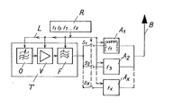
- the figure shows a conventional high-frequency transmitter T, for example for the frequency range between 20 and 80 MHz, it consists of a tunable oscillator O, a power amplifier V and a downstream tunable filter F.
- the individual frequency-determining elements of the transmitter T are via a control line L by a control device R tunable.
- the desired frequency scheme is programmed into the control device R; in the exemplary embodiment shown, it is entered, for example, that the transmitter T should be switched very quickly in the frequency sequence f1, f3, f7 ... fx, that is to say in a predetermined sequence of the transmission frequency of the selected frequency band .
- the out Transmitter of the transmitter is connected via very fast switches S1, S2, Sx to individual tuning branches A1, A2, Ax, which are connected to the antenna B on the output side. If necessary, additional fast switches connected synchronously with the switches on the input side can also be arranged between antenna B and matching branches.
- the switches S1, S2, Sx are preferably semiconductor switches which can be switched in the microsecond range.
- Each matching branch A1, A2, Ax is designed in a known manner and its reactance resistors can in turn be tuned to the various transmission frequencies entered there by means of relatively slow circuit breakers, for example reed relays, controlled by the control device R.
- the stored frequency sequence of the control device R is fixed, it must also be known on the receiving side.
- the first adaptation branch A4 is controlled by the control device R to the frequency f1, just like the transmitter T, and the switch S1 is closed, ie the transmitter transmits via the adaptation branch A1 and the antenna B.
- the second Adaptation branch A2 tuned to the frequency f3 that follows in the diagram. If the transmitter T is then switched to the next transmission frequency f3 via the control device R, S1 is simultaneously opened and S2 closed, that is to say the matching branch.A2 previously tuned to the frequency f3 is connected through to the antenna B. If three or more adaptation branches are provided, the adjustment time of the adaptation device can of course be shortened accordingly. It is also possible to provide as many matching branches A1 to Ax as the transmission frequencies f1 to fx. In this case, the branches only need to be tuned once to the respective frequency, when switching the frequency, only the associated switches S1 to Sx have to be operated.
Landscapes
- Engineering & Computer Science (AREA)
- Computer Networks & Wireless Communication (AREA)
- Signal Processing (AREA)
- Transmitters (AREA)
Abstract
Bei einer auf unterschiedliche Frequenzen abstimmbare Antennenanpasseinrichtung für einen Hochfrequenzsender, der über eine Steuereinrichtung nach einem vorbestimmten Frequenzschema schnell auf unterschiedliche Sendefrequenz umschaltbar ist, sind zum ebenso schnellen Abstimmen zwei oder mehrere jeweils auf unterschiedliche Frequenzen abstimmbare Anpasszweige vorgesehen, die über schnell schaltende Schalter zwischen Sender und Antenne schaltbar und über die Steuereinrichtung in der Frequenz abstimmbar sind.In the case of an antenna matching device for a high-frequency transmitter that can be tuned to different frequencies and that can be quickly switched to a different transmission frequency via a control device according to a predetermined frequency scheme, two or more matching branches that can be tuned to different frequencies are provided for the same quick tuning, via quick-switching switches between the transmitter and Antenna can be switched and the frequency can be tuned via the control device.
Description
Die Erfindung betrifft eine Antennenanpasseinrichtung laut Oberbegriff des Hauptanspruches.The invention relates to an antenna matching device according to the preamble of the main claim.
Bei zukünftigen Funkübertragungsverfahren wird oftmals ein sehr schneller Frequenzwechsel des Senders gefordert. So ist es beispielsweise zur Vermeidung von Störungen bekannt, den Sender sprunghaft nach einem bestimmten Frequenzschema umzuschalten,das auch empfangsseitig bekannt ist. Je nach Frequenzband liegen die Umschaltzeiten, die mit modernen Sendern möglich sind, im Bereich von Millisekunden oder sogar Mikrosekunden. Immer noch kürzere Zeiten werden bei diesem Verfahren angestrebt.In future radio transmission methods, a very fast frequency change of the transmitter is often required. For example, in order to avoid interference, it is known to switch the transmitter abruptly according to a specific frequency scheme, which is also known at the receiving end. Depending on the frequency band, the switchover times that are possible with modern transmitters are in the range of milliseconds or even microseconds. Even shorter times are aimed at with this method.
Die mit solchen Sendern betriebenen Antennen müssen in ihrem Widerstand an den Ausgangswiderstand des Senders angepasst werden, vor allem solche Antennen, die klein gegenüber der Wellenlänge sind und wie sie im mobilen Einsatz verwendet werden. Solche Antennenanpasseinrichtungen stellen Schwingkreise hoher Güte dar, in denen hohe Blindleistungen auftreten. Aus diesem Grunde müssen bei solchen Anpassgeräten zur Umschaltung der hier verwendeten Blindwiderstände Schalter verwendet werden, die relativ hohe Leistungen schalten können. Solche Schalter für höhere Leistungsbelastungen, beispielsweise übliche Vakuumrelais, besitzen jejoch relativ langsame Schaltzeiten. Modernere schnell schaltende Halbleiterschalter, wie sie im Sender verwendet werden, und wodurch die oben erwähnten kurzen Umschaltzeiten möglich sind, können wegen der höheren Leistungsbelastung nicht in solchen Anpassgeräten verwendet werden. Die Schnelligkeit der Frequenzumschaltung wird also bei Einrichtungen dieser Art bisher ausschliesslich durch die Schnelligkeit bestimmt, mit welcher das Anpassgerät in der Frequenz umschaltbar ist, in der Praxis sind höchstens Umschaltzeiten von einigen Millisekunden erreichbar. Dies ist für verschiedene oben erwähnte Anwendungsfälle, beispielsweise im militärischen Bereich, zu langsam.The antennas operated with such transmitters must be adjusted in their resistance to the output resistance of the transmitter, especially those antennas that are small compared to the wavelength and how they are used in mobile use. Such antenna matching devices represent high-quality resonant circuits in which high reactive powers occur. For this reason, switches that can switch relatively high powers must be used in such matching devices to switch over the reactive resistors used here. Such Switches for higher power loads, such as conventional vacuum relays, however, have relatively slow switching times. More modern, fast-switching semiconductor switches, such as those used in the transmitter, and as a result of which the short switching times mentioned above are possible, cannot be used in such matching devices because of the higher power load. So far, the speed of the frequency switching in devices of this type has been determined exclusively by the speed with which the adapter can be switched in frequency, in practice switching times of at most a few milliseconds can be achieved. This is too slow for various applications mentioned above, for example in the military field.
Es ist daher Aufgabe der Erfindung, eine Antennenanpasseinrichtung für einen schnell auf unterschiedliche Sendefrequenzen umschaltbaren Hochfrequenzsender zu schaffen, die genauso schnell wie der Sender in der Frequenz abstimmbar ist.It is therefore an object of the invention to provide an antenna matching device for a high-frequency transmitter which can be switched quickly to different transmission frequencies and which can be tuned in frequency just as quickly as the transmitter.
Diese Aufgabe wird ausgehend von einer Antennenanpasseinrichtung laut Oberbegriff des Hauptanspruches durch dessen kennzeichnende Merkmale gelöst. Vorteilhafte Weiterbildungen ergeben sich aus den Unteransprüchen.This object is achieved on the basis of an antenna matching device according to the preamble of the main claim by its characterizing features. Advantageous further developments result from the subclaims.
Durch die erfindungsgemässe Massnahme, zwei oder mehrere getrennte Antennenanpasszweige vorzusehen, ist es möglich, während des Sendens über den einen auf die momentane Sendefrequenz abgestimmten Zweig einen anderen Zweig auf die im Frequenzschema nächstfolgende Frequenz abzustimmen oder sogar mehrere andere Zweige auf die im Frequenzschema nächstfolgenden Frequenzen abzustimmen, so dass bei der anschliessenden Frequenzumschaltung des Senders nur noch über die schnell schaltbaren Schalter der nächste schon abgestimmte Zweig angeschaltet werden muss. Die zum Anschalten der Zweige vorgesehenen schnell schaltbaren Schalter sind beispielsweise genauso wie im Sender als Halbleiterschalter ausgeführt. Obwohl in den einzelnen Anpasszweigen also nach wie vor relativ langsame Schalter zum Abstimmen der Blindelemente auf die vorbestimmten Frequenzen vorgesehen sind, kann mit der erfindungsgemässen Einrichtung sehr schnell von einer Sendefrequenz auf die nächste umgeschaltet werden. Es ist damit möglich, auch solche Antennenanpasseinrichtungen genauso schnell wie moderne Sender im Millisekunden- bzw. Mikrosekundenbereich in der Frequenz umzuschalten. Nachdem über die Steuereinrichtung die Frequenzfolge bekannt ist, die ja auch im Emfpänger bekannt sein muss, ist es so beispielsweise schon mit zwei Zweigen möglich, das Anpassgerät schnell in der Frequenz umzuschalten. Zum Abstimmen der Anpasszweige steht jeweils die Zeit zur Verfügung, die zum Abstimmen des Senders und zur Ausstrahlung der Information auf einer vorgegebenen Frequenz zur Verfügung steht. Ist diese Zeit nicht ausreichend zur Abstimmung eines Antennenanpasszweiges, so ist es zweckmässig, mehr als zwei Anpasszweige vorzusehen und diese nacheinander auf die verschiedenen Frequenzen abzustimmen. Im Extremfall ist es sogar möglich und zweckmässig, genau soviel Anpasszweige vorzusehen wie jeweils für eine Übertragung nötige Sendefrequenzen im Sender umschaltbar sind. Hierbei kann es sich beispielsweise um zehn bis zwanzig verschiedene Sendefrequenzen und damit auch Anpasszweige handeln. Damit sind extrem kurze Abstimmzeiten erreichbar. In diesem Fall ist es nur nötig, zu Beginn einer Sendung alle Zweige auf die verschiedenen Sendefrequenzen einmal abzustimmen und dafür zu sorgen, dass diese Abstimmungen beibehalten werden. Beim Frequenzwechsel des Send rs müssen dann nur noch die jeweiligen Schalter der Anpasszweige betätigt werden, die wie gesagt als schnelle Halbleiterschalter ausgebildet sein können. Auf diese Weise können auch Umschaltzeiten im Mikrosekundenbereich für das Anpassgerät erreicht werden. Im allgemeinen genügt es, nur eingangsseitig die Anpasszweige über entsprechend schnelle Schalter mit dem Senderausgang zu verbinden, ausgangsseitig können die einzelnen Zweige zusammengefasst mit der Antenne verbunden sein. Um jedoch gegebenenfalls ausgangsseitig gewisse Rückwirkungen oder Leistungsbeeinflussungen der einzelnen Zweige zu vermeiden, kann es vorteilhaft sein, auch ausgangsseitig jeweils schnelle Schalter vorzusehen, über die jeweils nur der gerade wirksame Zweig mit der Antenne verbunden wird.The measure according to the invention of providing two or more separate antenna matching branches makes it possible to tune another branch to the frequency following in the frequency diagram or even to tune several other branches to the frequencies following in the frequency diagram while transmitting via one branch tuned to the current transmission frequency , so that when the transmitter is subsequently switched over, the next branch that has already been coordinated only has to be switched on using the quickly switchable switches. The quickly switchable switches provided for switching on the branches are designed, for example, in the same way as semiconductor switches in the transmitter. Although relatively slow switches for tuning the blind elements to the predetermined frequencies are still provided in the individual adaptation branches, the device according to the invention can be used to switch very quickly from one transmission frequency to the next. It is therefore possible to change the frequency of such antenna matching devices as quickly as modern transmitters in the millisecond or microsecond range. After the frequency sequence, which must also be known in the receiver, is known via the control device, it is thus possible, for example, with two branches to quickly switch the frequency of the adapter. The time available to tune the adaptation branches is available in each case for tuning the transmitter and for broadcasting the information on a predetermined frequency. If this time is not sufficient to tune an antenna matching branch, it is advisable to provide more than two matching branches and to adjust them one after the other to the different frequencies. In extreme cases, it is even possible and expedient to provide exactly as many adaptation branches as the transmission frequencies required for transmission in the transmitter can be switched over. This can be, for example, ten to twenty different transmission frequencies and thus also adaptation branches. This means that extremely short coordination times can be achieved. In this case, it is only necessary to tune all branches to the different transmission frequencies once and then there to ensure that these votes are maintained. When changing the frequency of the transmitter, only the respective switches of the matching branches then have to be actuated, which, as said, can be designed as fast semiconductor switches. In this way, switching times in the microsecond range can also be achieved for the adapter. In general, it is sufficient to connect the matching branches to the transmitter output only on the input side via correspondingly fast switches; on the output side, the individual branches can be combined with the antenna. However, in order to avoid certain repercussions or power influences of the individual branches on the output side, it can be advantageous to provide fast switches on the output side, through which only the currently active branch is connected to the antenna.
Die Erfindung wird im folgenden anhand-einer schematischen Zeichnung an einem Ausführungsbeispiel näher erläutert.The invention is explained below with reference to a schematic drawing of an embodiment.
Die Figur zeigt einen üblichen Hochfrequenzsender T beispielsweise für den Frequenzbereich zwischen 20 und 80 MHz, er besteht aus einem abstimmbaren Oszillator O, einem Leistungsverstärker V und einem nachgeschalteten abstimmbaren Filter F. Die einzelnen frequenzbestimmenden Elemente des Senders T sind über eine Steuerleitung L durch eine Steuereinrichtung R abstimmbar. In der Steuereinrichtung R ist das gewünschte Frequenzschema einprogrammiert, in dem gezeigten Ausführungsbeispiel ist beispielsweise eingegeben, dass der Sender T sehr schnell in der Frequenzfolge f1, f3, f7 ... fx umgeschaltet werden soll, also in einer vorbestimmten Reihenfolge der Sendefrequenz des ausgewählten Frequenzbandes. Der Ausgang des Senders steht über sehr schnelle Schalter S1, S2, Sx mit einzelnen Abstimmzweigen A1, A2, Ax in Verbindung, die ausgangsseitig mit der Antenne B verbunden sind. Gegebenenfalls können auch zwischen Antenne B und Anpasszweigen noch zusätzliche synchron mit den eingangsseitigen Schaltern geschaltete schnelle Schalter angeordnet sein. Die Schalter S1, S2, Sx sind vorzugsweise Halbleiterschalter, die im Mikrosekundenbereich schaltbar sind. Jeder Anpasszweig A1, A2, Ax ist in bekannter Weise ausgebildet und seine Blindwiderstände sind durch relativ langsame Leistungsschalter, beispielsweise Reedrelais, wiederum gesteuert durch die Steuereinrichtung R auf die verschiedenen dort eingegebenen Sendefrequenzen abstimmbar. Die eingespeicherte Frequenzfolge der Steuereinrichtung R liegt fest, sie muss ja auch auf der Empfangsseite bekannt sein. Angenommen, der erste Anpasszweig A4 ist gesteuert über die Steuereinrichtung R auf die Frequenz f1 abgestimmt, genauso wie der Sender T, und der Schalter S1 ist geschlossen, d.h. der Sender sendet über den Anpasszweig A1 und die Antenne B. Während dieser Sendezeit wird der zweite Anpasszweig A2 auf die im Schema nächstfolgende Frequenz f3 abgestimmt. Wird dann über die Steuereinrichtung R der Sender T auf die nächstfolgende Sendefrequenz f3 geschaltet, so wird gleichzeitig S1 geöffnet und S2 geschlossen, also der vorher auf die Frequenz f3 abgestimmte Anpasszweig.A2 zur Antenne B durchgeschaltet. Sind drei oder mehrere Anpasszweige vorgesehen, so kann hierdurch natürlich die Einstellzeit des Anpassgerätes noch entsprechend verkürzt werden. Es ist durchaus auch möglich, genau soviel Anpaßzweige A1 bis Ax vorzusehen wie Sendefrequenzen f1 bis fx vorgesehen sind. In diesem Fall brauchen die Zweige nur einmal auf die jeweilige Frequenz abgestimmt zu werden, bei der Frequenzumschaltung sind dann nur noch die zugehörigen Schalter S1 bis Sx zu betätigen.The figure shows a conventional high-frequency transmitter T, for example for the frequency range between 20 and 80 MHz, it consists of a tunable oscillator O, a power amplifier V and a downstream tunable filter F. The individual frequency-determining elements of the transmitter T are via a control line L by a control device R tunable. The desired frequency scheme is programmed into the control device R; in the exemplary embodiment shown, it is entered, for example, that the transmitter T should be switched very quickly in the frequency sequence f1, f3, f7 ... fx, that is to say in a predetermined sequence of the transmission frequency of the selected frequency band . The out Transmitter of the transmitter is connected via very fast switches S1, S2, Sx to individual tuning branches A1, A2, Ax, which are connected to the antenna B on the output side. If necessary, additional fast switches connected synchronously with the switches on the input side can also be arranged between antenna B and matching branches. The switches S1, S2, Sx are preferably semiconductor switches which can be switched in the microsecond range. Each matching branch A1, A2, Ax is designed in a known manner and its reactance resistors can in turn be tuned to the various transmission frequencies entered there by means of relatively slow circuit breakers, for example reed relays, controlled by the control device R. The stored frequency sequence of the control device R is fixed, it must also be known on the receiving side. Assume that the first adaptation branch A4 is controlled by the control device R to the frequency f1, just like the transmitter T, and the switch S1 is closed, ie the transmitter transmits via the adaptation branch A1 and the antenna B. During this transmission time, the second Adaptation branch A2 tuned to the frequency f3 that follows in the diagram. If the transmitter T is then switched to the next transmission frequency f3 via the control device R, S1 is simultaneously opened and S2 closed, that is to say the matching branch.A2 previously tuned to the frequency f3 is connected through to the antenna B. If three or more adaptation branches are provided, the adjustment time of the adaptation device can of course be shortened accordingly. It is also possible to provide as many matching branches A1 to Ax as the transmission frequencies f1 to fx. In this case, the branches only need to be tuned once to the respective frequency, when switching the frequency, only the associated switches S1 to Sx have to be operated.
Claims (4)
Applications Claiming Priority (2)
| Application Number | Priority Date | Filing Date | Title |
|---|---|---|---|
| DE3127566A DE3127566C2 (en) | 1981-07-11 | 1981-07-11 | Antenna matching device for a high-frequency transmitter operating according to the frequency hopping method |
| DE3127566 | 1981-07-11 |
Publications (4)
| Publication Number | Publication Date |
|---|---|
| EP0069979A2 true EP0069979A2 (en) | 1983-01-19 |
| EP0069979A3 EP0069979A3 (en) | 1984-10-03 |
| EP0069979B1 EP0069979B1 (en) | 1986-12-03 |
| EP0069979B2 EP0069979B2 (en) | 1991-01-23 |
Family
ID=6136758
Family Applications (1)
| Application Number | Title | Priority Date | Filing Date |
|---|---|---|---|
| EP82106058A Expired - Lifetime EP0069979B2 (en) | 1981-07-11 | 1982-07-07 | Matching circuit for antennas |
Country Status (3)
| Country | Link |
|---|---|
| US (1) | US4521913A (en) |
| EP (1) | EP0069979B2 (en) |
| DE (2) | DE3127566C2 (en) |
Cited By (4)
| Publication number | Priority date | Publication date | Assignee | Title |
|---|---|---|---|---|
| FR2574597A1 (en) * | 1984-12-06 | 1986-06-13 | Commissariat Energie Atomique | HIGH FREQUENCY ANTENNA TUNING DEVICE |
| EP0416476A3 (en) * | 1989-09-07 | 1991-05-22 | Standard Elektrik Lorenz Aktiengesellschaft | Circuit for connecting plural mutual decoupled frequency hopping transmitters to an antenna |
| FR2666417A1 (en) * | 1990-08-31 | 1992-03-06 | Tekelec Airtronic Sa | Method for checking the operation of a system comprising a filtering array and a user device such as an antenna connected to this array, and a layout for implementing this method |
| EP0532854A1 (en) * | 1991-07-25 | 1993-03-24 | TELEFUNKEN Sendertechnik GmbH | Tuning device for a long wavelength antenna |
Families Citing this family (18)
| Publication number | Priority date | Publication date | Assignee | Title |
|---|---|---|---|---|
| US4689803A (en) * | 1985-06-10 | 1987-08-25 | Megapulse Inc. | Antenna tuning system and method |
| IN165870B (en) * | 1985-06-25 | 1990-02-03 | Siemens Ag | |
| DE3527554A1 (en) * | 1985-08-01 | 1987-02-12 | Rohde & Schwarz | System for operating a short-wave transmitter according to the frequency hopping method |
| US5034697A (en) * | 1989-06-09 | 1991-07-23 | United States Of America As Represented By The Secretary Of The Navy | Magnetic amplifier switch for automatic tuning of VLF transmitting antenna |
| US5231355A (en) * | 1990-06-18 | 1993-07-27 | The Charles Machine Works, Inc. | Locator transmitter having an automatically tuned antenna |
| US5287550A (en) * | 1990-12-24 | 1994-02-15 | Motorola, Inc. | Simulcast scheduler |
| ES2151013T3 (en) * | 1991-02-19 | 2000-12-16 | Nec Corp | PEOPLE SEARCH RADIO. |
| DE4116126A1 (en) * | 1991-05-17 | 1992-11-19 | Telefunken Systemtechnik | Transmitter for frequency hopping operation - has hopping harmonic wave filter between HF power amplifier and aerial matching network |
| JP2866775B2 (en) * | 1991-12-26 | 1999-03-08 | 三星電子株式会社 | Antenna moving device and method |
| JPH0722971A (en) * | 1993-07-06 | 1995-01-24 | Mitsubishi Electric Corp | Wireless communication device |
| JP3444653B2 (en) | 1994-06-09 | 2003-09-08 | 三菱電機株式会社 | Power amplifier |
| JP2944444B2 (en) * | 1995-01-12 | 1999-09-06 | 日本電気株式会社 | Portable radio |
| EP0850512B1 (en) * | 1995-09-15 | 1999-07-07 | Siemens Aktiengesellschaft | Radio apparatus with several frequency ranges |
| FI114259B (en) * | 1999-07-14 | 2004-09-15 | Filtronic Lk Oy | Structure of a radio frequency front end |
| JP2002171111A (en) * | 2000-12-04 | 2002-06-14 | Anten Corp | Portable radio and antenna for it |
| US7433647B2 (en) * | 2005-05-12 | 2008-10-07 | Lear Corporation | Transmit antenna multiplexing for vehicular passive entry systems |
| JP4637774B2 (en) * | 2006-03-17 | 2011-02-23 | 富士通株式会社 | Mobile communication terminal |
| US8472904B2 (en) * | 2009-03-30 | 2013-06-25 | The Charles Stark Draper Laboratory, Inc. | Antenna with integrated tuning detection elements |
Family Cites Families (7)
| Publication number | Priority date | Publication date | Assignee | Title |
|---|---|---|---|---|
| US3129386A (en) * | 1962-05-21 | 1964-04-14 | Sunair Electronics Inc | Automatic antenna impedance matching and loading unit |
| US3277377A (en) * | 1963-10-25 | 1966-10-04 | Gen Motors Corp | Coupling circuit for all-transistor high frequency transmitter |
| US3566273A (en) * | 1968-06-07 | 1971-02-23 | Paul R Johannessen | Broadband high-q antenna system |
| US3794941A (en) * | 1972-05-08 | 1974-02-26 | Hughes Aircraft Co | Automatic antenna impedance tuner including digital control circuits |
| US3883875A (en) * | 1974-01-02 | 1975-05-13 | Int Standard Electric Corp | Endfire commutated antenna array |
| US3906405A (en) * | 1974-07-01 | 1975-09-16 | Motorola Inc | Tunable antenna coupling circuit |
| US4143369A (en) * | 1977-10-25 | 1979-03-06 | Northrop Corporation | Iff diversity switch |
-
1981
- 1981-07-11 DE DE3127566A patent/DE3127566C2/en not_active Expired
-
1982
- 1982-07-07 EP EP82106058A patent/EP0069979B2/en not_active Expired - Lifetime
- 1982-07-07 DE DE8282106058T patent/DE3274606D1/en not_active Expired
- 1982-07-09 US US06/396,715 patent/US4521913A/en not_active Expired - Fee Related
Cited By (6)
| Publication number | Priority date | Publication date | Assignee | Title |
|---|---|---|---|---|
| FR2574597A1 (en) * | 1984-12-06 | 1986-06-13 | Commissariat Energie Atomique | HIGH FREQUENCY ANTENNA TUNING DEVICE |
| EP0187560A1 (en) * | 1984-12-06 | 1986-07-16 | Commissariat A L'energie Atomique | Matching device for a HF antenna |
| US4672686A (en) * | 1984-12-06 | 1987-06-09 | Commissariat A L'energie Atomique | High frequency antenna tuning device |
| EP0416476A3 (en) * | 1989-09-07 | 1991-05-22 | Standard Elektrik Lorenz Aktiengesellschaft | Circuit for connecting plural mutual decoupled frequency hopping transmitters to an antenna |
| FR2666417A1 (en) * | 1990-08-31 | 1992-03-06 | Tekelec Airtronic Sa | Method for checking the operation of a system comprising a filtering array and a user device such as an antenna connected to this array, and a layout for implementing this method |
| EP0532854A1 (en) * | 1991-07-25 | 1993-03-24 | TELEFUNKEN Sendertechnik GmbH | Tuning device for a long wavelength antenna |
Also Published As
| Publication number | Publication date |
|---|---|
| DE3127566C2 (en) | 1984-03-08 |
| EP0069979B2 (en) | 1991-01-23 |
| US4521913A (en) | 1985-06-04 |
| EP0069979B1 (en) | 1986-12-03 |
| DE3127566A1 (en) | 1983-01-27 |
| EP0069979A3 (en) | 1984-10-03 |
| DE3274606D1 (en) | 1987-01-15 |
Similar Documents
| Publication | Publication Date | Title |
|---|---|---|
| EP0069979B1 (en) | Matching circuit for antennas | |
| DE60130315T2 (en) | Method and circuit for reducing the loss of a radio transmitter | |
| DE2645018C2 (en) | System for adaptive equalization of the amplitude response of a transmission channel | |
| EP1405370B1 (en) | Antenna connector arrangement, antenna signal splitter and method for receiver frequency control | |
| DD43058B1 (en) | CIRCUIT FOR ELECTRONIC TUNING OF A RADIO RECEPTACLE UNIT | |
| DE3311640C2 (en) | ||
| DE3509516C1 (en) | Circuit arrangement of the input stages of a television tuner | |
| EP0405349B1 (en) | Transmitter and/or receiver apparatus | |
| DE3020135C2 (en) | Circuit arrangement for the automatic setting of a radio receiver to a transmitter | |
| DE2553211C2 (en) | Coupling circuit for operating two radio receivers with a single antenna | |
| DE60100421T2 (en) | Multimodal communication device with a transceiver with multiple inputs | |
| EP0125453A2 (en) | Television or radio receiver | |
| WO1981001916A1 (en) | Input coupling device for a receiver | |
| EP1110317B1 (en) | Radio receiver equipment | |
| DE3618170C2 (en) | ||
| DE963613C (en) | Combined TV and FM radio receiver | |
| EP1150442B1 (en) | Antenna diversity circuit for radio receiver with several receiver branches | |
| CH647625A5 (en) | MANUAL SEARCH DEVICE. | |
| DE3701134A1 (en) | EXTREMELY BROADBAND RADIO RECEIVER | |
| DE1241503B (en) | Microwave crossover with simultaneous delay equalization | |
| DE4435753C2 (en) | Bi-directional transponder | |
| EP0316611B1 (en) | Vhf radio transmission installation using at least two transmitters with a different frequency | |
| DE3014540C2 (en) | Method and arrangement for tuning a heterodyne receiver | |
| DE978058C (en) | Procedure for disrupting and / or deceiving foreign radio links | |
| EP0734128A2 (en) | Radio data system broadcast receiver |
Legal Events
| Date | Code | Title | Description |
|---|---|---|---|
| PUAI | Public reference made under article 153(3) epc to a published international application that has entered the european phase |
Free format text: ORIGINAL CODE: 0009012 |
|
| AK | Designated contracting states |
Designated state(s): BE DE FR GB NL |
|
| PUAL | Search report despatched |
Free format text: ORIGINAL CODE: 0009013 |
|
| AK | Designated contracting states |
Designated state(s): BE DE FR GB NL |
|
| 17P | Request for examination filed |
Effective date: 19840920 |
|
| GRAA | (expected) grant |
Free format text: ORIGINAL CODE: 0009210 |
|
| AK | Designated contracting states |
Kind code of ref document: B1 Designated state(s): BE DE FR GB NL |
|
| REF | Corresponds to: |
Ref document number: 3274606 Country of ref document: DE Date of ref document: 19870115 |
|
| ET | Fr: translation filed | ||
| PLBI | Opposition filed |
Free format text: ORIGINAL CODE: 0009260 |
|
| 26 | Opposition filed |
Opponent name: SIEMENS AKTIENGESELLSCHAFT, BERLIN UND MUENCHEN Effective date: 19870722 |
|
| NLR1 | Nl: opposition has been filed with the epo |
Opponent name: SIEMENS AKTIENGESELLSCHAFT, |
|
| PUAH | Patent maintained in amended form |
Free format text: ORIGINAL CODE: 0009272 |
|
| STAA | Information on the status of an ep patent application or granted ep patent |
Free format text: STATUS: PATENT MAINTAINED AS AMENDED |
|
| 27A | Patent maintained in amended form |
Effective date: 19910123 |
|
| AK | Designated contracting states |
Kind code of ref document: B2 Designated state(s): BE DE FR GB NL |
|
| NLR2 | Nl: decision of opposition | ||
| NLR3 | Nl: receipt of modified translations in the netherlands language after an opposition procedure | ||
| ET3 | Fr: translation filed ** decision concerning opposition | ||
| PGFP | Annual fee paid to national office [announced via postgrant information from national office to epo] |
Ref country code: GB Payment date: 19910619 Year of fee payment: 10 |
|
| PGFP | Annual fee paid to national office [announced via postgrant information from national office to epo] |
Ref country code: NL Payment date: 19910731 Year of fee payment: 10 |
|
| PGFP | Annual fee paid to national office [announced via postgrant information from national office to epo] |
Ref country code: DE Payment date: 19910812 Year of fee payment: 10 |
|
| PG25 | Lapsed in a contracting state [announced via postgrant information from national office to epo] |
Ref country code: GB Effective date: 19920707 |
|
| PGFP | Annual fee paid to national office [announced via postgrant information from national office to epo] |
Ref country code: BE Payment date: 19920715 Year of fee payment: 11 |
|
| PG25 | Lapsed in a contracting state [announced via postgrant information from national office to epo] |
Ref country code: NL Effective date: 19930201 |
|
| GBPC | Gb: european patent ceased through non-payment of renewal fee |
Effective date: 19920707 |
|
| NLV4 | Nl: lapsed or anulled due to non-payment of the annual fee | ||
| PG25 | Lapsed in a contracting state [announced via postgrant information from national office to epo] |
Ref country code: DE Effective date: 19930401 |
|
| PG25 | Lapsed in a contracting state [announced via postgrant information from national office to epo] |
Ref country code: BE Effective date: 19930731 |
|
| BERE | Be: lapsed |
Owner name: ROHDE & SCHWARZ G.M.B.H. & CO. K.G. Effective date: 19930731 |
|
| PGFP | Annual fee paid to national office [announced via postgrant information from national office to epo] |
Ref country code: FR Payment date: 19970729 Year of fee payment: 16 |
|
| PG25 | Lapsed in a contracting state [announced via postgrant information from national office to epo] |
Ref country code: FR Free format text: LAPSE BECAUSE OF NON-PAYMENT OF DUE FEES Effective date: 19990331 |
|
| REG | Reference to a national code |
Ref country code: FR Ref legal event code: ST |