EP0069898A2 - Multirow harvester, especially for maize - Google Patents
Multirow harvester, especially for maize Download PDFInfo
- Publication number
- EP0069898A2 EP0069898A2 EP82105669A EP82105669A EP0069898A2 EP 0069898 A2 EP0069898 A2 EP 0069898A2 EP 82105669 A EP82105669 A EP 82105669A EP 82105669 A EP82105669 A EP 82105669A EP 0069898 A2 EP0069898 A2 EP 0069898A2
- Authority
- EP
- European Patent Office
- Prior art keywords
- receiving
- knife
- drum
- harvester according
- gap
- Prior art date
- Legal status (The legal status is an assumption and is not a legal conclusion. Google has not performed a legal analysis and makes no representation as to the accuracy of the status listed.)
- Granted
Links
Images


Classifications
-
- A—HUMAN NECESSITIES
- A01—AGRICULTURE; FORESTRY; ANIMAL HUSBANDRY; HUNTING; TRAPPING; FISHING
- A01D—HARVESTING; MOWING
- A01D43/00—Mowers combined with apparatus performing additional operations while mowing
- A01D43/08—Mowers combined with apparatus performing additional operations while mowing with means for cutting up the mown crop, e.g. forage harvesters
- A01D43/081—Mowers combined with apparatus performing additional operations while mowing with means for cutting up the mown crop, e.g. forage harvesters specially adapted for ensilage of maize
- A01D43/082—Gathering units
Definitions
- the invention relates to a multi-row harvesting machine for stalked stalk material, in particular for maize, with a plurality of receiving gaps formed by stalk dividers, in each of which a receiving drum is provided on the delivery side, which has at least two receiving disks arranged one above the other, equipped with drivers, and a lower cutting device for the stalk material and rotate in pairs in opposite directions and bring the cut and gripped stalk material from two adjacent receiving gaps to two downstream, upright feed rollers, which form a feed gap between them.
- the pick-up drums carry two upper, spaced-apart pick-up disks and a lower knife star, which, together with a counter knife, cuts the plants off just above the ground.
- the two holding disks are used for grasping and conveying the separated plants, the drivers of the lower holding disk having shorter distances have from each other than the drivers of the upper receiving disc; the purpose of this is that the lower receiving disk, above all, grips and supports the stems securely, while the upper receiving disk serves more to guide the stems.
- each take-up drum transfers the crop to the downstream feed roller, which detects the crop, whereupon it passes through the feed gap between the two feed rollers into a feed device of a chopper.
- the known harvesting machine has between all take-up disks and between the lowest take-up disk and the knife star Scraper attached, which extend from the take-up drum to the area between the two feed rollers.
- the invention is based on the object of improving a multi-row harvesting machine of the type described at the outset so that only cleanly cut stalk material without adhering foreign bodies such as lumps of earth, stones or roots is conveyed from the take-up drums to the feed rollers, so that the risk of blockage of the Feed gap is avoided.
- this object is achieved in that essentially only S-shaped wipers are provided between the upper receiving disks of each receiving drum, which come from the drum jacket and lead into the feed gap.
- a guide part protruding from the gap and ensuring an orderly and trouble-free merging of the two crop flows is provided.
- the guide part is particularly advantageous when the pick-up drums are pivotally mounted on the harvesting machine in such a way that they can be adapted to different row spacings of the plants to be harvested.
- the free ends of this movement are also moved - the scraper is moved in such a way that they are pivoted along - the opposite surfaces of the flag, so that in no position of the recording drum the vertical gap between the free ends of the wipers is opened too much.
- the straws transported by the receiving disks into the feed gap are always properly guided in this way, so that the straw material cannot get into the gap between the free ends of the wipers and is conveyed back again or can cause blockages.
- each take-up drum is derived from the downstream feed roller.
- the drive connection can be designed as a gear transmission or as a chain or belt drive and can be accommodated in a protected housing, which is attached so as to be pivotable and lockable about the axis of rotation of the associated feed roller.
- the cutting device consists of at least one rotating double knife with two cutting edges and a fixed counter knife with an essentially U-shaped machine in the direction of travel of the harvesting machine and against the direction of rotation of the Double knife is open cutting edge, the base connecting the two U-legs inclined to the radial of the receiving drum carrying the cutting device and obliquely with respect to the direction of travel from the outside inwards at the rear by an angle ⁇ , and that the two cutting edges of the double knife with the radial two different angles Include ⁇ and ⁇ , where ⁇ > ⁇ ;> ⁇ .
- the double knife has a flat cutting edge that forms an open angle with the base of the U-shaped cutting edge of the counter knife during the cutting process, and a steep cutting edge that forms an inward angle with the base during the cutting process.
- the angle ⁇ is approximately 30 °, the angle ⁇ is approximately 37 ° and the angle ⁇ is approximately 22 °.
- the position of the counter knife to the double knife is adjustable.
- the counter knife is screwed onto a knife carrier with the interposition of spring elements.
- This measure ensures that the cutting device always has a perfect cutting action.
- FIG. 1 schematically shows the side view of a two-row harvesting machine 10 for maize, which can be laterally coupled to a tractor in a known manner.
- the harvesting machine 10 has three straw dividers 12y tapering to a point in the direction of travel F, as a result of which two receiving gaps are formed.
- a delivery side i.e. Arranged in the direction of travel F at the rear is a take-up drum 14, which separates the plants from the ground in a manner to be described and conveys them to the feed nip 16 between two upright feed rollers 18, which convey the crop into a chopping device 20.
- the two feed rollers 18 are mounted on a base frame 22 of the harvesting machine 10 at a fixed distance from one another and can be driven in opposite directions; the direction of rotation is indicated in Fig. 4 by arrows.
- the two conical feed rollers 18 have loop-like drivers 24, the drivers of one feed roller engaging in rotation between two drivers of the opposite feed roller and thus the cut and and convey crops fed in from the take-up drums 14 through the feed gap 16 to the chopping device 20 in cooperation with the take-up drums.
- the two receiving drums 14 are each attached to a shaft 26 which is mounted in a gear housing 28.
- Each of the two gear case 28 h is about the rotational axis 30 of the associated egg - zugswalze mounted pivotably 18, so that the mutual distance of the two receiving drums 14 can be adapted to the respective row spacing of the crop, and then detected.
- the transmission for the drive of the take-up drum 14 derived from the associated feed roller 18 is accommodated in the two transmission housings 28; the transmission can be designed as a gear transmission or as a chain or belt drive.
- each take-up drum 14 On the drum 32 of each take-up drum 14, three take-up disks 34, 36, 38 are fastened axially one above the other and at a distance from one another. As shown in FIG. 3, the two take-up drums 14 are offset from one another in the axial direction, so that the take-up disks of one take-up drum 14 run in the overlap region into the space between the take-up disks of the other take-up drum.
- the direction of rotation of the two receiving drums 14 is shown in FIG. 4.
- the upper receiving disk 34 and the middle receiving disk 36 have drivers 40 on their outer circumference, the distance between the drivers 40 of the middle receiving disk 36 being less than in the case of the upper receiving disk 34.
- the central receiving disk 36 serves primarily to securely close the cut-off stems detect and promote in the direction of the feed rollers 18, while the upper receiving disc 34 is to guide the stems.
- a knife star 42 is fastened to the lower receiving disk 38 and, as is shown primarily in FIG. 6, is composed of three double knives 44.
- Each of the two knife stars 42 is assigned a counter knife 46, which is fastened on a knife carrier 48 by three screws 50 and with the interposition of disc springs 52. Fastening by means of three screws prevents undesired tilting movements of the counter knife 46.
- the knife carrier 48 for its part, is screwed to the gear housing 28. 4 that the two counter knives 46 are arranged on the mutually facing outer sides of the two receiving drums 14.
- Each double knife 44 which has approximately the shape of two adjacent, mirror-symmetrical triangles in plan view, has a flat cutting edge 54 and a steep cutting edge 56.
- the flat cutting edge 54 forms an angle / 3 of approximately 37 ° with the radial of the receiving drum 14, while the steep cutting edge 56 forms an angle ⁇ of approximately 22 ° with the radial.
- the fixed counter knife 46 has an essentially U-shaped cutting edge which is open in the direction of travel F of the harvesting machine 10 and against the direction of rotation (arrow A in FIG. 6) of the double knife 44.
- the two U-legs 58 are connected by a base 60, also serving as a cutting edge, which is inclined to the radial by an angle .alpha. the angle ⁇ is about 30 ° in the embodiment.
- the flat cutting edge 54 of the double knife 54 forms, as shown in FIG. 7, at the moment of the cutting process with the base 60 of the fixed counter knife 46 an outwardly open angle, while the steep cutting edge 56 then forms an inwardly open angle with the base 60 when the knife star 42 rotates in the direction A.
- This ensures that the plant stems are separated from the ground in a pulling cut on two different sides of the cutting edge, alternately at the outer and the inner end of the base 60 of the cutting edge of the counter knife 46. In this way, a uniform wear is the Cutting edges brought about, and it is also ensured that possibly by the flat cutting edge 54 not completely severed blades by the subsequent steep cutting edge 56 in the other cutting direction are still cut.
- the double knife 44 Due to the mirror-symmetrical shape of the double knife 44, it is possible to replace the double knife of the two counter-rotating drum 14 after a certain period of use, so that the two unused and therefore sharp cutting edges of each double knife are used. This doubles the service life of the knives.
- Fastening the two counter knives 46 on the knife carriers 48 with the aid of screws 50 with the interposition of the plate springs 52 has the advantage that there remains a distance between the two that is available for adjustment.
- 52 spring blocks or other spring elements instead of the plate springs.
- a stripper 62 is also arranged between the upper pick-up disk 34 and the middle pick-up disk 36 of each pick-up drum 14, which is bent approximately S-shaped in plan view and, starting from the drum jacket of the pick-up drum 14, into the feed gap 16 between the two feed rollers 18 leads in.
- Each wiper 62 is fastened with a holder 64, which in turn is fastened on the associated gear housing 28.
- the free ends 66 of the two wipers 62 form a vertical gap, between which, as shown in particular in FIG. 4, a guide part 68 is provided.
- the guide part consists of an upright base body 70, which is fastened to the base frame 22, and a tab 72 projecting therefrom, which protrudes from the vertical gap between the two free ends 66 of the wipers 62.
- the S-shape of the two wipers 62, the free ends 66 of which run angled backwards counter to the direction of travel F, is selected such that the cut stalk material which is gripped and guided by the two holding disks 34 and 36 is guided from the two adjacent holding gaps under effect of the guide part 68 is securely merged into the feed nip 16 and this merging takes place only in an area in which the two feed rollers 18 securely grasp the goods.
- the angle 0 between the wipers 62 and the tangents on the outer edges of the drivers 40 of the two receiving disks 34 and 36 is chosen so that it is always greater than 90 °.
- the flag 72 of the guide part 68 closes the vertical gap between the free ends 66 of the two wipers 62, so that the merged crop material is prevented from being squeezed into this area.
Landscapes
- Life Sciences & Earth Sciences (AREA)
- Environmental Sciences (AREA)
- Harvesting Machines For Specific Crops (AREA)
- Harvester Elements (AREA)
Abstract
Description
Die Erfindung betrifft eine mehrreihige Erntemaschine für stengeliges Halmgut, insbesondere für Mais, mit mehreren von Halmteilern gebildeten Aufnahmespalten, in denen ab - gabeseitig je eine Aufnahmetrommel vorgesehen ist, die wenigstens zwei übereindander angeordnete, mit Mitnehmern ausgerüstete Aufnahmescheiben sowie eine untere Schneideinrichtung für das Halmgut haben und die paarweise gegensinnig rotieren und das abgeschnittene und erfaßte Halmgut aus zwei nebeneinanderliegenden Aufnahmespalten zusammenführen zu zwei nachgeschalteten, aufrechtstehenden Einzugswalzen, die zwischen sich einen Einzugsspalt bilden.The invention relates to a multi-row harvesting machine for stalked stalk material, in particular for maize, with a plurality of receiving gaps formed by stalk dividers, in each of which a receiving drum is provided on the delivery side, which has at least two receiving disks arranged one above the other, equipped with drivers, and a lower cutting device for the stalk material and rotate in pairs in opposite directions and bring the cut and gripped stalk material from two adjacent receiving gaps to two downstream, upright feed rollers, which form a feed gap between them.
Bei einer zweireihigen Erntemaschine dieser Bauart tragen die Aufnahmetrommeln zwei obere, voneinander beabstandete Aufnahmescheiben sowie einen unteren Messerstern, der zusammen mit einem Gegenmesser die Pflanzen kurz über dem Boden abtrennt. Die beiden Aufnahmescheiben dienen zum Erfassen und Fördern der abgetrennten Pflanzen, wobei die Mitnehmer der unteren Aufnahmescheibe geringere Abstände voneinander aufweisen als die Mitnehmer der oberen Auf - nahmescheibe; das hat den Zweck, daß die untere Aufnahmescheibe vor allem die Stengel sicher erfaßt und fördert , während die obere Aufnahmescheibe mehr zur Führung der Stengel dient. An der der Fahrtrichtung abgewandten Seite übergibt jede Aufnahmetrommel das Halmgut an die nachgeschaltete Einzugswalze, die das Halmgut erfaßt, worauf dieses durch den Einzugsspalt zwischen den beiden Einzugswalzen hindurch in eine Einzugsvorrichtung eines Häckslers gelangt. Um die Übergabe des Halmgutes zu verbessern und um zu verhindern, daß dieses von den rotierenden Aufnahmetrommeln wieder zurückgefördert wird, ohne daß es von den Einzugswalzen erfaßt worden ist, sind bei der bekannten Ernte - maschine zwischen allen Aufnahmescheiben und zwischen der untersten Aufnahmescheibe und dem Messerstern Abstreifer angebracht, die sich von der Aufnahmetrommel bis in den Bereich zwischen den beiden Einzugswalzen erstrecken.In a two-row harvesting machine of this type, the pick-up drums carry two upper, spaced-apart pick-up disks and a lower knife star, which, together with a counter knife, cuts the plants off just above the ground. The two holding disks are used for grasping and conveying the separated plants, the drivers of the lower holding disk having shorter distances have from each other than the drivers of the upper receiving disc; the purpose of this is that the lower receiving disk, above all, grips and supports the stems securely, while the upper receiving disk serves more to guide the stems. On the side facing away from the direction of travel, each take-up drum transfers the crop to the downstream feed roller, which detects the crop, whereupon it passes through the feed gap between the two feed rollers into a feed device of a chopper. In order to improve the transfer of the stalk and to prevent it from being conveyed back by the rotating take-up drums without being caught by the feed rollers, the known harvesting machine has between all take-up disks and between the lowest take-up disk and the knife star Scraper attached, which extend from the take-up drum to the area between the two feed rollers.
Bei dieser bekannten Erntemaschine kann es insbesondere bei unebenen Bodenverhältnissen vorkommen, daß nicht nur abgeschnittenes Halmgut in den Einzugsspalt gelangt, sondern auch Erdbrocken, die zusammen mit den unteren Stengelenden herausgerissen worden sind und nun durch die Abstreifer zwischen dem Messerstern und der darüberliegenden Aufnahmescheibe in den Einzugsspalt gedrückt werden , wodurch dieser nach kurzer Zeit verstopft wird. Auch können dabei die Abstreifer beschädigt werden.In this known harvesting machine, it can happen, in particular in the case of uneven ground conditions, that not only cut stalk material gets into the feed gap, but also lumps of earth that have been torn out together with the lower ends of the stalk and now through the wipers between the knife star and the overlying receiving disc into the feed gap are pressed, which clogs it after a short time. The wipers can also be damaged.
Der Erfindung liegt die Aufgabe zugrunde, eine mehrreihige Erntemaschine der eingangs erläuterten Gattung so zu verbessern, daß nur sauber abgeschnittenes Halmgut ohne anhaftende Fremdkörper wie Erdklumpen, Steine oder Wurzel - werk von den Aufnahmetrommeln zu den Einzugswalzen gefördert wird, so daß die Gefahr einer Verstopfung des Einzugsspaltes vermieden ist.The invention is based on the object of improving a multi-row harvesting machine of the type described at the outset so that only cleanly cut stalk material without adhering foreign bodies such as lumps of earth, stones or roots is conveyed from the take-up drums to the feed rollers, so that the risk of blockage of the Feed gap is avoided.
Erfindungsgemäß wird diese Aufgabe dadurch gelöst, daß nur zwischen den oberen Aufnahmescheiben jeder Aufnahmetrommel im wesentlichen S-förmig gebogene Abstreifer vorgesehen sind, die vom Trommelmantel ausgehen und in den Einzugs - spalt hineinführen.According to the invention, this object is achieved in that essentially only S-shaped wipers are provided between the upper receiving disks of each receiving drum, which come from the drum jacket and lead into the feed gap.
Auf diese'Weise wird erreicht, daß an den unteren Stengelenden anhaftendes Erdreich oder dergleichen nicht zu dem Einzugsspalt hin abgelenkt wird, sondern in dem Raum zwischen der unteren Aufnahmescheibe und der darunter angeordneten Schneideinrichtung (Messerstern) entgegenge - setzt zur Fahrtrichtung der Erntemaschine zurückgefördert und durch die Drehgeschwindigkeit der Aufnahmetrommeln bei normalen Bodenverhältnissen abgeschleudert wird. Die Vereinigung der Stengel zweier Erntereihen durch die paar - weise angeordneten Aufnahmetrommeln und die von diesen zu dem Einzugsspalt führenden Abstreifer wird dadurch nicht beeinträchtigt.In this way it is achieved that soil or the like adhering to the lower ends of the stalk is not deflected towards the feed gap, but instead is conveyed back in the space between the lower receiving disc and the cutting device (knife star) arranged underneath to the direction of travel of the harvesting machine and through the speed of rotation of the take-up drums is thrown off under normal ground conditions. The union of the stems of two rows of crops by the paired receiving drums and the wipers leading from them to the feed gap is not impaired by this.
Die Fachwelt war bisher der Auffassung, daß für eine ordnungsgemäße Führung des Halmgutes zu den Einzugswalzen und zwischen dem Messerstern und der darüberliegenden Aufnahmescheibe Abstreifer vorgesehen sein_müssen. Versuche mit erfindungsgemäß ausgebildeten Erntemaschinen haben jedoch gezeigt, daß das nicht erforderlich ist.The professional world was previously of the opinion that wipers must be provided for proper guidance of the stalk material to the feed rollers and between the knife star and the overlying receiving disc. Experiments with harvesting machines designed according to the invention have shown, however, that this is not necessary.
Es hat sich als vorteilhaft erwiesen, wenn der Winkel zwischen dem Abstreifer und den Mitnehmern der zugehörigen Aufnahmescheiben bzw. den Tangenten an die äußere Kante der Mitnehmer immer größer ist als 90°.It has proven to be advantageous if the angle between the scraper and the drivers of the associated receiving disks or the tangents to the outer edge of the drivers is always greater than 90 °.
Durch diese Maßnahme wird eine störungsfreie Übergabe der abgeschnittenen Halme von den Mitnehmern der Aufnahmescheiben zu den Abstreifern gewährleistet, ohne daß ein Verklemmen eintritt. Außerdem hat sich herausgestellt, daß dadurch das Einziehen von nicht verwertbaren Stengelteilen und Unkraut zwischen Aufnahmescheiben und Abstreifer verhindert wird.This measure ensures a trouble-free transfer of the cut stalks from the drivers of the holding discs to the wipers without jamming occurring. It has also been found that this prevents the ingestion of unusable stem parts and weeds between the holding discs and the scraper.
Nach einem anderen Merkmal der Erfindung ist zwischen den einen vertikalen Spalt bildenden, freien Enden von je zwei Abstreifern im Bereich des Einzugsspaltes ein aus dem Spalt herausragendes, ein geordnetes und störungsfreies Zusammenführen der beiden Halmgutströme gewährleistendes Führungs - teil vorgesehen.According to another feature of the invention, between the free ends of two wipers forming a vertical gap in the area of the feed gap, a guide part protruding from the gap and ensuring an orderly and trouble-free merging of the two crop flows is provided.
Dieses kann aus einem aufrechtstehenden Grundkörper und einer davon abstehenden Fahne bestehen, die aus dem vertikalen Spalt zwischen den freien Enden der beiden Abstreifer herausragt.This can consist of an upright base body and a protruding tab, which protrudes from the vertical gap between the free ends of the two wipers.
Das Führungsteil ist insbesondere dann von Vorteil, wenn die Aufnahmetrommeln derart schwenkbar an der Erntemaschine gelagert sind, daß eine Anpassung an unterschiedliche Rei - henabstände der zu erntenden Pflanzen durchgeführt werden kann. Beim Verschwenken der Aufnahmetrommeln zueinander werden auch die freien Enden der diese Bewegung mitmachen - den Abstreifer bewegt, und zwar so, daß sie an-den gegen - überliegenden Flächen der Fahne entlang geschwenkt werden, so daß in keiner Stellung der Aufnahmetrommel der vertikale Spalt zwischen den freien Enden der Abstreifer zu sehr geöffnet wird. Die von den Aufnahmescheiben in den Einzugsspalt transportierten Halme werden auf diese Weise immer einwandfrei geführt, so daß das Halmgut nicht in den Spalt zwischen den freien Enden der Abstreifer gelangen kann und wieder zurückgefördert wird oder Verstopfungen hervorrufen kann.The guide part is particularly advantageous when the pick-up drums are pivotally mounted on the harvesting machine in such a way that they can be adapted to different row spacings of the plants to be harvested. When pivoting the recording drums to each other, the free ends of this movement are also moved - the scraper is moved in such a way that they are pivoted along - the opposite surfaces of the flag, so that in no position of the recording drum the vertical gap between the free ends of the wipers is opened too much. The straws transported by the receiving disks into the feed gap are always properly guided in this way, so that the straw material cannot get into the gap between the free ends of the wipers and is conveyed back again or can cause blockages.
Zur Anpassung der Aufnahmetrommeln an unterschiedliche Reihenabstände des Erntegutes ist es weiter vorteilhaft, wenn der Antrieb jeder Aufnahmetrommel von der nachgeschalteten Einzugswalze abgeleitet ist. Die Antriebsverbindung kann dabei als Zahnradgetriebe oder als Ketten- oder Riementrieb ausgebildet und in einem Gehäuse geschützt untergebracht sein, das um die Drehachse der zugeordneten Einzugswalze verschwenkbar und feststellbar angebracht ist.To adapt the take-up drums to different row spacings of the crop, it is further advantageous if the drive of each take-up drum is derived from the downstream feed roller. The drive connection can be designed as a gear transmission or as a chain or belt drive and can be accommodated in a protected housing, which is attached so as to be pivotable and lockable about the axis of rotation of the associated feed roller.
Die eingangs erläuterte Aufgabe wird bei einer gattungsge - mäßen Vorrichtung auch dadurch gelöst, daß die Schneidein - richtung aus wenigstens einem rotierenden Doppelmesser mit zwei Schneidkanten und einem feststehenden Gegenmesser mit im wesentlichen U-förmiger, in Fahrtrichtung der Ernte - maschine und gegen die Drehrichtung der Doppelmesser offenen Schneidkante besteht, deren die beiden U-Schenkel verbindende Basis zur Radialen der die Schneideinrichtung tragenden Aufnahmetrommel geneigt und bezüglich der Fahrtrichtung von außen nach innen hinten um einen Winkel α schräg verläuft, und daß die beiden Schneidkanten des Doppelmessers mit der Radialen zwei unterschiedliche Winkel β und γ einschließen, wobei β >α ;> γ.The above-described object is also achieved in a generic device in that the cutting device consists of at least one rotating double knife with two cutting edges and a fixed counter knife with an essentially U-shaped machine in the direction of travel of the harvesting machine and against the direction of rotation of the Double knife is open cutting edge, the base connecting the two U-legs inclined to the radial of the receiving drum carrying the cutting device and obliquely with respect to the direction of travel from the outside inwards at the rear by an angle α, and that the two cutting edges of the double knife with the radial two different angles Include β and γ, where β> α;> γ.
Bei dieser Lösung hat das Doppelmesser eine flache Schneidkante, die beim Schneidvorgang mit der Basis der Ü-förmigen Schneidkante des Gegenmessers einen nach außen offenen Winkel bildet, und eine steile Schneidkante, die beim Schneidvorgang mit der Basis einen nach innen offenen Winkel bildet. Damit wird erreicht, daß das Halmgut immer von zwei verschiedenen Seiten durch je einen ziehenden Schnitt sicher abgetrennt wird, wodurch verhindert wird, daß nur teilweise abgetrennte Stengel, die über nicht durchtrennte Fasern mit dem unteren Stengelende verbunden bleiben, Wurzelwerk, daran anhängendes Erdreich und Unkraut mitreißen, das so in den Einzugsspalt zwischen den beiden Einzugswalzen gerät. Ein weiterer Vorteil besteht darin, daß aufgrund des ziehenden Schnittes keine punktförmige Beanspruchung der Schneidkanten an immer gleichbleibenden Stellen erfolgt, sondern eine gleichmäßige Beanspruchung, die eine längere Stand - zeit der Messer zur Folge hat.In this solution, the double knife has a flat cutting edge that forms an open angle with the base of the U-shaped cutting edge of the counter knife during the cutting process, and a steep cutting edge that forms an inward angle with the base during the cutting process. This ensures that the stalks are always safely separated from two different sides by a pulling cut, which prevents that only partially separated stems, which remain connected to the lower end of the stem via uncut fibers, root system, attached soil and weeds entrain, which gets into the feed gap between the two feed rollers. Another advantage is that due to the pulling cut there is no punctiform stress on the cutting edges at always constant locations, but instead an even load, which results in a longer service life of the knives.
In der Praxis hat es sich als vorteilhaft erwiesen, wenn der Winkel α etwa 30°, der Winkel β etwa 37° und der Winkel γetwa 22° betragen.In practice, it has proven to be advantageous if the angle α is approximately 30 °, the angle β is approximately 37 ° and the angle γ is approximately 22 °.
Nach einem weiteren Merkmal der Erfindung ist die Lage des Gegenmessers zum Doppelmesser einstellbar. Hierfür ist es günstig, wenn das Gegenmesser unter Zwischenschaltung von Federelementen auf einem Messerträger verschraubt ist.According to a further feature of the invention, the position of the counter knife to the double knife is adjustable. For this purpose, it is advantageous if the counter knife is screwed onto a knife carrier with the interposition of spring elements.
Mit dieser Maßnahme wird eine stets einwandfreie Schneidwirkung der Schneideinrichtung sichergestellt.This measure ensures that the cutting device always has a perfect cutting action.
Es ist ferner von Vorteil, wenn drei Doppelmesser zu einem rotierenden Messerstern vereinigt sind, so daß bei jeder Rotation des Messersterns sechs abwechselnde Schnitte erfolgen.It is also advantageous if three double knives are combined to form a rotating knife star, so that six alternating cuts are made with each rotation of the knife star.
Die Erfindung ist nachstehend an einem Ausführungsbeispiel erläutert, das in der Zeichnung dargestellt ist.The invention is explained below using an exemplary embodiment which is illustrated in the drawing.
Es zeigen :
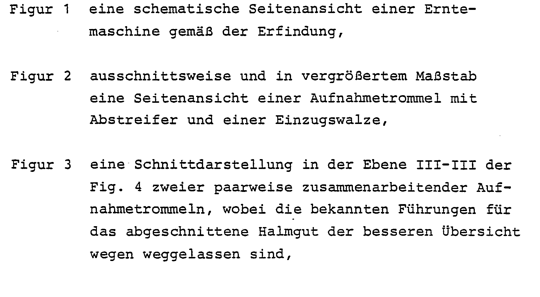

In Figur 1 ist schematisch die Seitenansicht einer zweireihigen Erntemaschine 10 für Mais gezeigt, die in bekannter Weise seitlich an einen Schlepper gekoppelt werden kann . Die Erntemaschine 10 hat drei in Fahrtrichtung F spitz zulaufende Halmteiler 12y wodurch zwei Aufnahmespalten gebildet werden. In jedem Aufnahmespalt ist abgabeseitig, d.h. in Fahrtrichtung F hinten eine Aufnahmetrommel 14 angeordnet, die in noch zu beschreibender Weise die Pflanzen vom Boden abtrennt und zu dem Einzugsspalt 16 zwischen zwei aufrechtstehenden Einzugswalzen 18 fördert, welche das Erntegut in eine Häckseleinrichtung 20 weiterleiten.FIG. 1 schematically shows the side view of a two-
Die beiden Einzugswalzen 18 sind auf einem Grundrahmen 22 der Erntemaschine 10 mit festem Abstand zueinander und gegensinnig antreibbar gelagert; die Drehrichtung ist in Fig. 4 durch Pfeile angedeutet. An der Außenseite weisen die beiden konischen Einzugswalzen 18 schlaufenartige Mitnehmer 24 auf, wobei die Mitnehmer der einen Einzugswalze bei der Drehung zwischen zwei Mitnehmer der gegenüberliegenden Einzugswalze eingreifen und so das geschnittene und und von den Aufnahmetrommeln 14 zugeführte Erntegut durch den Einzugsspalt 16 zur Häckseleinrichtung 20 in Zusammenwirken mit den Aufnahmetrommeln weiterfördern.The two
Die beiden Aufnahmetrommeln 14 sind, wie vor allem Fig. 5 zeigt, auf je einer Welle 26 befestigt, die in einem Getriebegehäuse 28 gelagert ist. Jedes der beiden Getriebegehäuse 28 ist um die Drehachse 30 der zugeordneten Eih- zugswalze 18 verschwenkbar gelagert, so daß der gegenseitige Abstand der beiden Aufnahmetrommeln 14 an den jeweiligen Reihenabstand des Erntegutes angepaßt und anschließend festgestellt werden kann. In den beiden Getriebegehäusen 28 ist das Getriebe für den von der zugeordneten Einzugswalze 18 abgeleiteten Antrieb der Aufnahmetrommel 14 untergebracht; das Getriebe kann als Zahnradgetriebe oder als Ketten-oder Riementrieb ausgebildet sein.As is shown primarily in FIG. 5, the two receiving
Auf der Trommel 32 jeder Aufnahmetrommel 14 sind axial übereinander und mit Abstand zueinander drei Aufnahmescheiben 34,36,38 befestigt. Wie Fig. 3 zeigt, sind die beiden Aufnahmetrommeln 14 in_Axialrichtung versetzt zueinander angeordnet, so daß die Aufnahmescheiben der einen Aufnahmetrommel 14 im Überlappungsbereich in den Zwischenraum zwischen den Aufnahmescheiben der anderen Aufnahme - trommel laufen. Die Drehrichtung der beiden Aufnahme - trommeln 14 ist in Fig. 4 eingezeichnet. Die obere Aufnahmescheibe 34 und die mittlere Aufnahmescheibe 36 weisen an ihrem Außenumfang Mitnehmer 40 auf, wobei der Abstand der Mitnehmer 40 der mittleren Aufnahmescheibe 36 geringer ist als bei der oberen Aufnahmescheibe 34. Die mittlere Aufnahmescheibe 36 dient vor allem dazu, die abgeschnittenen Stengel sicher zu erfassen und in Richtung auf die Einzugswalzen 18 zu fördern, während die obere Aufnahmescheibe 34 die Stengel führen soll.On the
An der unteren Aufnahmescheibe 38 ist ein Messerstern 42 befestigt, der, wie vor allem Fig. 6 zeigt, aus drei Doppelmessern 44 zusammengesetzt ist. Jedem der beiden Messer - sterne 42 ist ein Gegenmesser 46 zugeordnet, das auf einem Messerträger 48 durch drei Schrauben 50 und unter Zwischenschaltung von Tellerfedern 52 befestigt ist. Die Befesti - gung mittels drei Schrauben verhindert unerwünschte Kippbewegungen des Gegenmessers 46. Der Messerträger 48 seiner - seits ist am Getriebegehäuse 28 verschraubt. Aus Fig. 4 geht hervor, daß die beiden Gegenmesser 46 an den voneinander wegweisenden Außenseiten der beiden Aufnahmetrommeln 14 angeordnet sind.A
Jedes Doppelmesser 44, das in Draufsicht etwa die Form von zwei nebeneinanderliegenden, spiegelsymmetrischen Dreiecken aufweist, hat eine flache Schneidkante 54 und eine steile Schneidkante 56. Die flache Schneidkante 54 bildet dabei mit der Radialen der Aufnahmetrommel 14 einen Winkel /3 von etwa 37° , während die steile Schneidkante 56 mit der Radialen einen Winkel γ von etwa 22° einschließt. Das feststehende Gegenmesser 46 hat eine im wesentlichen U-förmige Schneidkante, die in Fahrtrichtung F der Erntemaschine 10 und gegen die Drehrichtung (Pfeil A in Fig.6) der Doppelmesser 44 offen ist. Die beiden U-Schenkel 58 werden von einer ebenfalls als Schneidkante dienenden Basis 60 verbunden, die zur Radialen um einen Winkel α bezüglich der Fahrtrichtung F von außen nach innen hinten geneigt verläuft; der Winkel α beträgt beim Ausführungsbeispiel etwa 30°.Each
Da die Größe des Winkels α der Basis 16 zwischen der Größe der Winkel /3 und γ der beiden Schneidkanten 54 und 56 liegt, bildet, wie Fig. 7 zeigt, die flache Schneidkante 54 des Doppelmessers 54 im Augenblick des Schneidvor - gangs mit der Basis 60 des feststehenden Gegenmessers 46 einen nach außen offenen Winkel, während die steile Schneidkante 56 bei der Drehung des Messersternes 42 in Richtung A anschließend mit der Basis 60 einen nach innen offenen Winkel bildet. Damit wird erreicht, daß die Pflanzenstengel an zwei verschiedenen Seiten der Schneidkante in einem ziehenden Schnitt vom Boden getrennt werden, und zwar abwechselnd an dem äußeren und an dem inneren Ende der Basis 60 der Schneidkante des Gegenmessers 46. Auf diese Weise ist eine gleichmäßige Abnutzung der Schneidkanten herbeigeführt, und außerdem ist sichergestellt, daß möglicherweise durch die flache Schneidkante 54 nicht vollständig durchtrennte Halme durch die nachfolgende, steile Schneidkante 56 in der anderen Schnittrichtung doch noch durchtrennt werden.Since the size of the angle α of the
Aufgrund der spiegelsymmetrischen Form der Doppelmesser 44 ist es möglich, die Doppelmesser der beiden gegensinnig rotierenden Aufnahmetrommeln 14 nach einer gewissen Einsatzzeit gegeneinander auszutauschen, so daß die beiden noch unbenutzten und damit scharfen Schneidkanten jedes Doppelmessers zum Einsatz kommen. Die Standzeit der Messer wird dadurch verdoppelt.Due to the mirror-symmetrical shape of the
Zur Verringerung des Verschleißes und zur Verbesserung der Schneidwirkung sind alle Schneidkanten mit einer Hartmetallbeschichtung versehen. Die Aufteilung des Messersterns 42 in drei Doppelmesser 44 beugt der Gefahr eines Verziehens , insbesondere bei der Herstellung und dem Montieren vor.To reduce wear and improve the cutting effect, all cutting edges are provided with a hard metal coating. The division of the
Die Befestigung der beiden Gegenmesser 46 auf den Messer - trägern 48 mit Hilfe von Schrauben 50 unter Zwischenschaltung der Tellerfedern 52 hat den Vorteil, daß zwischen beiden ein Abstand bleibt, der zur Einstellung zur Verfügung steht. Selbstverständlich ist es auch möglich, anstelle der Tellerfedern 52 Federblöcke oder andere Federelemente zu verwenden.Fastening the two
Bei der erfindungsgemäßen Erntemaschine 10 ist ferner zwischen der oberen Aufnahmescheibe 34 und der mittleren Aufnahmescheibe 36 jeder Aufnahmetrommel 14 ein Abstreifer 62 angeordnet, der in Draufsicht etwa S-förmig gebogen ist und vom Trommelmantel der Aufnahmetrommel 14 ausgehend in den Einzugsspalt 16 zwischen den beiden Einzugswalzen 18 hineinführt. Jeder Abstreifer 62 ist mit einer Halterung 64 befestigt, die ihrerseits auf dem zugehörigen Getriebegehäuse 28 befestigt ist.In the harvesting
Die freien Enden 66 der beiden Abstreifer 62 bilden einen vertikalen Spalt, zwischen dem, wie vor allem Fig. 4 zeigt, ein Führungsteil 68 vorgesehen ist. Das Führungsteil besteht aus einem aufrechtstehenden Grundkörper 70, der am Grundrahmen 22 befestigt ist, und einer davon abstehenden Fahne 72, die aus dem vertikalen Spalt zwischen den beiden freien Enden 66 der Abstreifer 62 herausragt.The free ends 66 of the two
Die S-Form der beiden Abstreifer 62, deren freie Enden 66 entgegen der Fahrtrichtung F nach hinten abgewinkelt aus - laufen, ist so gewählt, daß das abgeschnittene und von den beiden Aufnahmescheiben 34 und 36 erfaßte und geführte Halmgut aus den beiden nebeneinanderliegenden Aufnahmespalten unter Wirkung des Führungsteils 68 sicher in den Einzugsspalt 16 zusammengeführt wird und diese Zusammenführung erst in einem Bereich erfolgt, in dem die beiden Einzugswalzen 18 das Gut sicher erfassen. Der Winkel 0 zwischen den Abstreifern 62 und den Tangenten an den äußeren Kanten der Mitnehmer 40 der beiden Aufnahmescheiben 34 und 36 ist dabei so gewählt, daß er immer größer ist als 90° .The S-shape of the two
Die Fahne 72 des Führungsteils 68 verschließt den vertikalen Spalt zwischen den freien Enden 66 der beiden Abstreifer 62, so daß ein Hineinquetschen des zusammengeführten Halmgutes in diesen Bereich verhindert wird. Wenn zur Anpassung der Erntemaschine 10 an unterschiedliche Reihenabstände des Erntegutes die beiden Aufnahmetrommeln 14 zu - sammen mit ihren Getriebegehäusen und den an diesen befestigten beiden äußeren Halmteilern 12 um die Drehachsen 30 der beiden Einzugswalzen 18 geschwenkt werden, schwenken die freien Enden 66 der beiden Abstreifer 62 an der Fahne 72 des Führungsteils 68 entlang, wodurch dafür gesorgt ist, daß stets eine wirksame Führungsfläche für das Erntegut vorhanden ist.The
Claims (11)
Priority Applications (3)
| Application Number | Priority Date | Filing Date | Title |
|---|---|---|---|
| DE8484109130T DE3274615D1 (en) | 1981-07-10 | 1982-06-28 | Multirow-harvester, especially for maize |
| AT84109130T ATE24088T1 (en) | 1981-07-10 | 1982-06-28 | MULTI-ROW HARVESTER, ESPECIALLY FOR CORN. |
| AT82105669T ATE17299T1 (en) | 1981-07-10 | 1982-06-28 | MULTI-ROW HARVESTER, ESPECIALLY FOR CORN. |
Applications Claiming Priority (2)
| Application Number | Priority Date | Filing Date | Title |
|---|---|---|---|
| DE3127388 | 1981-07-10 | ||
| DE19813127388 DE3127388A1 (en) | 1981-07-10 | 1981-07-10 | MULTI-ROW HARVESTING MACHINE, ESPECIALLY FOR MAIZE |
Related Child Applications (1)
| Application Number | Title | Priority Date | Filing Date |
|---|---|---|---|
| EP84109130.9 Division-Into | 1984-08-01 |
Publications (3)
| Publication Number | Publication Date |
|---|---|
| EP0069898A2 true EP0069898A2 (en) | 1983-01-19 |
| EP0069898A3 EP0069898A3 (en) | 1983-05-04 |
| EP0069898B1 EP0069898B1 (en) | 1986-01-08 |
Family
ID=6136661
Family Applications (2)
| Application Number | Title | Priority Date | Filing Date |
|---|---|---|---|
| EP84109130A Expired EP0135724B1 (en) | 1981-07-10 | 1982-06-28 | Multirow-harvester, especially for maize |
| EP82105669A Expired EP0069898B1 (en) | 1981-07-10 | 1982-06-28 | Multirow harvester, especially for maize |
Family Applications Before (1)
| Application Number | Title | Priority Date | Filing Date |
|---|---|---|---|
| EP84109130A Expired EP0135724B1 (en) | 1981-07-10 | 1982-06-28 | Multirow-harvester, especially for maize |
Country Status (2)
| Country | Link |
|---|---|
| EP (2) | EP0135724B1 (en) |
| DE (3) | DE3127388A1 (en) |
Cited By (15)
| Publication number | Priority date | Publication date | Assignee | Title |
|---|---|---|---|---|
| EP0135724A1 (en) * | 1981-07-10 | 1985-04-03 | Alois Pöttinger Maschinenfabrik GmbH | Multirow-harvester, especially for maize |
| FR2559995A1 (en) * | 1984-02-23 | 1985-08-30 | Krone Bernhard Gmbh Maschf | Rotary cutter assembly for maize harvester |
| US4594842A (en) * | 1982-07-17 | 1986-06-17 | Maschinenfabrik Kemper Gmbh | Machine for harvesting and chopping of maize or similar stalk-type harvests |
| EP0673594A1 (en) * | 1994-03-22 | 1995-09-27 | Karl Moosbrucker | Mowing device for stem cereals |
| EP0882389A1 (en) * | 1997-06-07 | 1998-12-09 | Same Deutz-Fahr S.P.A. | Cutting mechanism for non row crop |
| AT404915B (en) * | 1997-08-14 | 1999-03-25 | Busatis Gmbh | SAW WITH A BASE AND TEETH AND METHOD FOR PRODUCING A SAW |
| US6032444A (en) * | 1997-06-04 | 2000-03-07 | Hay & Forage Industries | Non-row-sensitive forage harvester |
| DE10037534A1 (en) * | 2000-08-01 | 2002-02-14 | Kemper Gmbh Maschf | Machine for mowing stalk-like crops |
| EP1530893A1 (en) * | 2003-11-05 | 2005-05-18 | Maschinenfabrik Bernard Krone GmbH | Harvesting device |
| US7478520B2 (en) | 2006-06-03 | 2009-01-20 | Maschinenfabrik Kemper Gmbh & Co Kg | Machine for harvesting stalk-like plants with a stripper |
| CN103548489A (en) * | 2013-11-18 | 2014-02-05 | 吉林大学 | High-stubble reserving type maize harvesting machine |
| CN110741830A (en) * | 2019-11-27 | 2020-02-04 | 山东理工大学 | Airborne disc cutter type cotton topping device with front standing grain lifting baffle |
| CN112119757A (en) * | 2020-11-02 | 2020-12-25 | 聊城市厚德机电有限公司 | Novel poppy harvester and working method thereof |
| CN113424697A (en) * | 2021-06-24 | 2021-09-24 | 冉正贵 | Garlic reaps with rhizome cutting device |
| CN115004937A (en) * | 2022-06-01 | 2022-09-06 | 河南农业大学 | Fresh corn picking device |
Families Citing this family (3)
| Publication number | Priority date | Publication date | Assignee | Title |
|---|---|---|---|---|
| DE102007038276B3 (en) * | 2007-08-14 | 2009-03-26 | Maschinenfabrik Kemper Gmbh & Co. Kg | Harvested stalk-like plant i.e. maize, mowing machine, has counter blade with lower part arranged below cutting blade and upper part arranged above cutting blade, where counter blade encloses cutting blade with close gap |
| CN104521423A (en) * | 2014-12-24 | 2015-04-22 | 郑州中联收获机械有限公司 | Maize harvesting machine and header of maize harvesting machine |
| CN112042378B (en) * | 2020-08-14 | 2021-08-31 | 淮阴工学院 | Multi-row Chinese chive harvester |
Citations (4)
| Publication number | Priority date | Publication date | Assignee | Title |
|---|---|---|---|---|
| DE2612857A1 (en) * | 1976-03-26 | 1977-10-06 | Mengele & Soehne Masch Karl | HALMERNTEGERAET |
| FR2408293A1 (en) * | 1977-11-09 | 1979-06-08 | Sperry Rand Nv | EQUIPMENT FOR HARVESTING MARGINAL CROPS |
| DE2900554A1 (en) * | 1978-01-12 | 1979-07-19 | Poettinger Ohg Alois | DEVICE FOR PICKING UP, SEPARATING AND TRANSFERRING STACKED CROP IN A ROW, IN PARTICULAR CORN |
| DE2900552A1 (en) * | 1978-01-12 | 1979-07-19 | Poettinger Ohg Alois | DEVICE FOR PICKING UP AND SEPARATING AND, IF NECESSARY, FORWARDING STACKED CROP IN A ROW, IN PARTICULAR CORN |
Family Cites Families (3)
| Publication number | Priority date | Publication date | Assignee | Title |
|---|---|---|---|---|
| DE2524894A1 (en) * | 1975-06-04 | 1976-12-16 | Fahr Ag Maschf | FEEDING DEVICE ON A FIELD HARVESTER |
| DE2621716C2 (en) * | 1976-05-15 | 1983-01-20 | Karl Mengele & Söhne Maschinenfabrik und Eisengießerei GmbH & Co, 8870 Günzburg | Forage harvester |
| DE3127388A1 (en) * | 1981-07-10 | 1983-02-03 | Alois Pöttinger Maschinenfabrik GmbH, 4710 Grieskirchen | MULTI-ROW HARVESTING MACHINE, ESPECIALLY FOR MAIZE |
-
1981
- 1981-07-10 DE DE19813127388 patent/DE3127388A1/en not_active Withdrawn
-
1982
- 1982-06-28 DE DE8484109130T patent/DE3274615D1/en not_active Expired
- 1982-06-28 EP EP84109130A patent/EP0135724B1/en not_active Expired
- 1982-06-28 DE DE8282105669T patent/DE3268386D1/en not_active Expired
- 1982-06-28 EP EP82105669A patent/EP0069898B1/en not_active Expired
Patent Citations (4)
| Publication number | Priority date | Publication date | Assignee | Title |
|---|---|---|---|---|
| DE2612857A1 (en) * | 1976-03-26 | 1977-10-06 | Mengele & Soehne Masch Karl | HALMERNTEGERAET |
| FR2408293A1 (en) * | 1977-11-09 | 1979-06-08 | Sperry Rand Nv | EQUIPMENT FOR HARVESTING MARGINAL CROPS |
| DE2900554A1 (en) * | 1978-01-12 | 1979-07-19 | Poettinger Ohg Alois | DEVICE FOR PICKING UP, SEPARATING AND TRANSFERRING STACKED CROP IN A ROW, IN PARTICULAR CORN |
| DE2900552A1 (en) * | 1978-01-12 | 1979-07-19 | Poettinger Ohg Alois | DEVICE FOR PICKING UP AND SEPARATING AND, IF NECESSARY, FORWARDING STACKED CROP IN A ROW, IN PARTICULAR CORN |
Cited By (20)
| Publication number | Priority date | Publication date | Assignee | Title |
|---|---|---|---|---|
| EP0135724A1 (en) * | 1981-07-10 | 1985-04-03 | Alois Pöttinger Maschinenfabrik GmbH | Multirow-harvester, especially for maize |
| US4594842A (en) * | 1982-07-17 | 1986-06-17 | Maschinenfabrik Kemper Gmbh | Machine for harvesting and chopping of maize or similar stalk-type harvests |
| FR2559995A1 (en) * | 1984-02-23 | 1985-08-30 | Krone Bernhard Gmbh Maschf | Rotary cutter assembly for maize harvester |
| EP0673594A1 (en) * | 1994-03-22 | 1995-09-27 | Karl Moosbrucker | Mowing device for stem cereals |
| US6032444A (en) * | 1997-06-04 | 2000-03-07 | Hay & Forage Industries | Non-row-sensitive forage harvester |
| EP0882389A1 (en) * | 1997-06-07 | 1998-12-09 | Same Deutz-Fahr S.P.A. | Cutting mechanism for non row crop |
| AT404915B (en) * | 1997-08-14 | 1999-03-25 | Busatis Gmbh | SAW WITH A BASE AND TEETH AND METHOD FOR PRODUCING A SAW |
| EP1535505A1 (en) | 2000-08-01 | 2005-06-01 | Maschinenfabrik Kemper GmbH & Co. KG | Machine for mowing stalk crops |
| US6502378B2 (en) | 2000-08-01 | 2003-01-07 | Deere & Company | Forage harvester header having conveyor arrangement for controlling crop stalks |
| DE10037534A1 (en) * | 2000-08-01 | 2002-02-14 | Kemper Gmbh Maschf | Machine for mowing stalk-like crops |
| EP1530893A1 (en) * | 2003-11-05 | 2005-05-18 | Maschinenfabrik Bernard Krone GmbH | Harvesting device |
| US7478520B2 (en) | 2006-06-03 | 2009-01-20 | Maschinenfabrik Kemper Gmbh & Co Kg | Machine for harvesting stalk-like plants with a stripper |
| CN103548489A (en) * | 2013-11-18 | 2014-02-05 | 吉林大学 | High-stubble reserving type maize harvesting machine |
| CN103548489B (en) * | 2013-11-18 | 2015-12-02 | 吉林大学 | One stays high stubble formula maize harvesting machine |
| CN110741830A (en) * | 2019-11-27 | 2020-02-04 | 山东理工大学 | Airborne disc cutter type cotton topping device with front standing grain lifting baffle |
| CN112119757A (en) * | 2020-11-02 | 2020-12-25 | 聊城市厚德机电有限公司 | Novel poppy harvester and working method thereof |
| CN113424697A (en) * | 2021-06-24 | 2021-09-24 | 冉正贵 | Garlic reaps with rhizome cutting device |
| CN113424697B (en) * | 2021-06-24 | 2024-04-05 | 南京迈凯通机械设备有限公司 | Garlic reaps and uses rhizome cutting device |
| CN115004937A (en) * | 2022-06-01 | 2022-09-06 | 河南农业大学 | Fresh corn picking device |
| CN115004937B (en) * | 2022-06-01 | 2023-10-27 | 河南农业大学 | Fresh corn picking device |
Also Published As
| Publication number | Publication date |
|---|---|
| DE3268386D1 (en) | 1986-02-20 |
| EP0135724A1 (en) | 1985-04-03 |
| EP0069898A3 (en) | 1983-05-04 |
| EP0069898B1 (en) | 1986-01-08 |
| DE3274615D1 (en) | 1987-01-22 |
| EP0135724B1 (en) | 1986-12-10 |
| DE3127388A1 (en) | 1983-02-03 |
Similar Documents
| Publication | Publication Date | Title |
|---|---|---|
| EP0508189B1 (en) | Machine for mowing and chopping maize and such stalk crops | |
| EP0069898B1 (en) | Multirow harvester, especially for maize | |
| DE2848451C2 (en) | ||
| EP1106049B1 (en) | Corn gathering and picking device with a chopping device | |
| DE19959338A1 (en) | Feeding and picking device and harvesting machine | |
| EP1078567B1 (en) | Apparatus for harvesting corn or similar grain | |
| DE19959281A1 (en) | Feeding and picking device of a crop recovery device | |
| DE1507187B1 (en) | Harvesting device for stalk-shaped stalks, especially maize | |
| EP1161857A1 (en) | Gathering and picking device | |
| EP0712567A1 (en) | Device for mowing and conveying stalk crops | |
| EP1430765B1 (en) | Machine for mowing of stalk-like crop and releasable cleaning element | |
| EP0094036A1 (en) | Salvage device for a seed harvester | |
| DE3115723C2 (en) | Front attachment for a corn harvester | |
| CH657746A5 (en) | DEVICE FOR THE PREPARATION OF CUT STRAWS. | |
| DE10257776A1 (en) | Feeding and picking device | |
| DE102007035791B3 (en) | Mowing and collecting device for stalk-like plants harvesting machine, has holder with straight edge that together with scraper closes narrow gap such that undesired accumulation of residues of harvested plant are removed by scraper | |
| DE2758098A1 (en) | HALMERNTEGERAET | |
| EP3130214B1 (en) | Mowing and conveyor apparatus for harvesting stalk crops | |
| AT392194B (en) | MACHINE FOR HARVESTING CORN OD. DGL. STICK-LIKE HARVEST | |
| EP2071934B1 (en) | Machine for harvesting stalk-like plants | |
| DE102013106197A1 (en) | The gathering | |
| EP1862058B1 (en) | Machine for harvesting stalk-like plants with a stripper | |
| DE2900554C2 (en) | ||
| DE2621716C2 (en) | Forage harvester | |
| EP0882389A1 (en) | Cutting mechanism for non row crop |
Legal Events
| Date | Code | Title | Description |
|---|---|---|---|
| PUAI | Public reference made under article 153(3) epc to a published international application that has entered the european phase |
Free format text: ORIGINAL CODE: 0009012 |
|
| AK | Designated contracting states |
Designated state(s): AT CH DE FR LI |
|
| PUAL | Search report despatched |
Free format text: ORIGINAL CODE: 0009013 |
|
| AK | Designated contracting states |
Designated state(s): AT CH DE FR LI |
|
| 17P | Request for examination filed |
Effective date: 19831024 |
|
| GRAA | (expected) grant |
Free format text: ORIGINAL CODE: 0009210 |
|
| AK | Designated contracting states |
Designated state(s): AT CH DE FR LI |
|
| REF | Corresponds to: |
Ref document number: 17299 Country of ref document: AT Date of ref document: 19860115 Kind code of ref document: T |
|
| REF | Corresponds to: |
Ref document number: 3268386 Country of ref document: DE Date of ref document: 19860220 |
|
| ET | Fr: translation filed | ||
| PGFP | Annual fee paid to national office [announced via postgrant information from national office to epo] |
Ref country code: AT Payment date: 19860620 Year of fee payment: 5 |
|
| PLBE | No opposition filed within time limit |
Free format text: ORIGINAL CODE: 0009261 |
|
| STAA | Information on the status of an ep patent application or granted ep patent |
Free format text: STATUS: NO OPPOSITION FILED WITHIN TIME LIMIT |
|
| 26N | No opposition filed | ||
| PG25 | Lapsed in a contracting state [announced via postgrant information from national office to epo] |
Ref country code: LI Effective date: 19870630 Ref country code: CH Effective date: 19870630 |
|
| REG | Reference to a national code |
Ref country code: CH Ref legal event code: PL |
|
| PG25 | Lapsed in a contracting state [announced via postgrant information from national office to epo] |
Ref country code: AT Effective date: 19890628 |
|
| PGFP | Annual fee paid to national office [announced via postgrant information from national office to epo] |
Ref country code: DE Payment date: 19910619 Year of fee payment: 10 |
|
| PGFP | Annual fee paid to national office [announced via postgrant information from national office to epo] |
Ref country code: FR Payment date: 19910625 Year of fee payment: 10 |
|
| PG25 | Lapsed in a contracting state [announced via postgrant information from national office to epo] |
Ref country code: FR Effective date: 19930226 |
|
| PG25 | Lapsed in a contracting state [announced via postgrant information from national office to epo] |
Ref country code: DE Effective date: 19930302 |
|
| REG | Reference to a national code |
Ref country code: FR Ref legal event code: ST |