EP0069716A2 - Vorrichtung zum Entschärfen von Explosionskörpern - Google Patents
Vorrichtung zum Entschärfen von Explosionskörpern Download PDFInfo
- Publication number
- EP0069716A2 EP0069716A2 EP82850142A EP82850142A EP0069716A2 EP 0069716 A2 EP0069716 A2 EP 0069716A2 EP 82850142 A EP82850142 A EP 82850142A EP 82850142 A EP82850142 A EP 82850142A EP 0069716 A2 EP0069716 A2 EP 0069716A2
- Authority
- EP
- European Patent Office
- Prior art keywords
- drill
- motor
- holding part
- casing
- unit
- Prior art date
- Legal status (The legal status is an assumption and is not a legal conclusion. Google has not performed a legal analysis and makes no representation as to the accuracy of the status listed.)
- Withdrawn
Links
Images
Classifications
-
- B—PERFORMING OPERATIONS; TRANSPORTING
- B23—MACHINE TOOLS; METAL-WORKING NOT OTHERWISE PROVIDED FOR
- B23Q—DETAILS, COMPONENTS, OR ACCESSORIES FOR MACHINE TOOLS, e.g. ARRANGEMENTS FOR COPYING OR CONTROLLING; MACHINE TOOLS IN GENERAL CHARACTERISED BY THE CONSTRUCTION OF PARTICULAR DETAILS OR COMPONENTS; COMBINATIONS OR ASSOCIATIONS OF METAL-WORKING MACHINES, NOT DIRECTED TO A PARTICULAR RESULT
- B23Q5/00—Driving or feeding mechanisms; Control arrangements therefor
- B23Q5/22—Feeding members carrying tools or work
- B23Q5/32—Feeding working-spindles
- B23Q5/326—Feeding working-spindles screw-operated
-
- B—PERFORMING OPERATIONS; TRANSPORTING
- B23—MACHINE TOOLS; METAL-WORKING NOT OTHERWISE PROVIDED FOR
- B23Q—DETAILS, COMPONENTS, OR ACCESSORIES FOR MACHINE TOOLS, e.g. ARRANGEMENTS FOR COPYING OR CONTROLLING; MACHINE TOOLS IN GENERAL CHARACTERISED BY THE CONSTRUCTION OF PARTICULAR DETAILS OR COMPONENTS; COMBINATIONS OR ASSOCIATIONS OF METAL-WORKING MACHINES, NOT DIRECTED TO A PARTICULAR RESULT
- B23Q11/00—Accessories fitted to machine tools for keeping tools or parts of the machine in good working condition or for cooling work; Safety devices specially combined with or arranged in, or specially adapted for use in connection with, machine tools
- B23Q11/04—Arrangements preventing overload of tools, e.g. restricting load
-
- B—PERFORMING OPERATIONS; TRANSPORTING
- B23—MACHINE TOOLS; METAL-WORKING NOT OTHERWISE PROVIDED FOR
- B23Q—DETAILS, COMPONENTS, OR ACCESSORIES FOR MACHINE TOOLS, e.g. ARRANGEMENTS FOR COPYING OR CONTROLLING; MACHINE TOOLS IN GENERAL CHARACTERISED BY THE CONSTRUCTION OF PARTICULAR DETAILS OR COMPONENTS; COMBINATIONS OR ASSOCIATIONS OF METAL-WORKING MACHINES, NOT DIRECTED TO A PARTICULAR RESULT
- B23Q9/00—Arrangements for supporting or guiding portable metal-working machines or apparatus
- B23Q9/0014—Portable machines provided with or cooperating with guide means supported directly by the workpiece during action
- B23Q9/0042—Portable machines provided with or cooperating with guide means supported directly by the workpiece during action the guide means being fixed only on the workpiece
- B23Q9/005—Portable machines provided with or cooperating with guide means supported directly by the workpiece during action the guide means being fixed only on the workpiece angularly adjustable
-
- F—MECHANICAL ENGINEERING; LIGHTING; HEATING; WEAPONS; BLASTING
- F42—AMMUNITION; BLASTING
- F42B—EXPLOSIVE CHARGES, e.g. FOR BLASTING, FIREWORKS, AMMUNITION
- F42B33/00—Manufacture of ammunition; Dismantling of ammunition; Apparatus therefor
- F42B33/06—Dismantling fuzes, cartridges, projectiles, missiles, rockets or bombs
-
- Y—GENERAL TAGGING OF NEW TECHNOLOGICAL DEVELOPMENTS; GENERAL TAGGING OF CROSS-SECTIONAL TECHNOLOGIES SPANNING OVER SEVERAL SECTIONS OF THE IPC; TECHNICAL SUBJECTS COVERED BY FORMER USPC CROSS-REFERENCE ART COLLECTIONS [XRACs] AND DIGESTS
- Y10—TECHNICAL SUBJECTS COVERED BY FORMER USPC
- Y10T—TECHNICAL SUBJECTS COVERED BY FORMER US CLASSIFICATION
- Y10T408/00—Cutting by use of rotating axially moving tool
- Y10T408/13—Cutting by use of rotating axially moving tool with randomly-actuated stopping means
- Y10T408/14—Responsive to condition of Tool or tool-drive
-
- Y—GENERAL TAGGING OF NEW TECHNOLOGICAL DEVELOPMENTS; GENERAL TAGGING OF CROSS-SECTIONAL TECHNOLOGIES SPANNING OVER SEVERAL SECTIONS OF THE IPC; TECHNICAL SUBJECTS COVERED BY FORMER USPC CROSS-REFERENCE ART COLLECTIONS [XRACs] AND DIGESTS
- Y10—TECHNICAL SUBJECTS COVERED BY FORMER USPC
- Y10T—TECHNICAL SUBJECTS COVERED BY FORMER US CLASSIFICATION
- Y10T408/00—Cutting by use of rotating axially moving tool
- Y10T408/16—Cutting by use of rotating axially moving tool with control means energized in response to activator stimulated by condition sensor
- Y10T408/17—Cutting by use of rotating axially moving tool with control means energized in response to activator stimulated by condition sensor to control infeed
- Y10T408/172—Responsive to Tool
-
- Y—GENERAL TAGGING OF NEW TECHNOLOGICAL DEVELOPMENTS; GENERAL TAGGING OF CROSS-SECTIONAL TECHNOLOGIES SPANNING OVER SEVERAL SECTIONS OF THE IPC; TECHNICAL SUBJECTS COVERED BY FORMER USPC CROSS-REFERENCE ART COLLECTIONS [XRACs] AND DIGESTS
- Y10—TECHNICAL SUBJECTS COVERED BY FORMER USPC
- Y10T—TECHNICAL SUBJECTS COVERED BY FORMER US CLASSIFICATION
- Y10T408/00—Cutting by use of rotating axially moving tool
- Y10T408/18—Cutting by use of rotating axially moving tool with stopping upon completion of prescribed operation
Definitions
- the present invention relates to an apparatus for penetrating a casing wall, particularly the casing wall of a detonating or firing mechanism, when disarming an undetonated explosive object, such as a live bomb, shell, mine, torpedo etc.
- An object of the present invention is to provide an apparatus with which the aforementioned risks are considerably reduced.
- an apparatus of the kind mentioned in the introduction comprises a drill unit driven by an electric motor; a carrier means for carrying the drill unit in substantially any selected position relative to said explosive object; feed means for moving in a controllable fashion at least a part of the drill unit holding the drill in the axial direction of said drill; and means for detecting a decrease in drill torque responsive to penetration of the drill through said wall.
- the detecting means may, to advantage, include a signal means, suitably in the form of a signal lamp, arranged on a remote-control device adapted to enable the operating current to said motor to be made and broken at a safe distance from the explosive object, and , preferably, also to enable the drive direction of said motor to be reversed.
- the motor housing of the drill unit is rotatable about the motor axis and is co-ordinated with a preferably adjustable spring means which strives to rotate the motor housing in a direction coinciding with the direction of rotation of the motor shaft when drilling, with a force so restricted that it is able to prevent the motor housing from rotating in the direction opposite to said direction of rotation only when the drill does not carry-out work with the motor running, said detecting means including means for detecting the position of rotation of the motor housing,
- the motor housing may, to particular advantage, carry means for actuating a switch means in dependence on the position of rotation of the motor housing, said switch means being incorporated in a current circuit for actuating at least one electrically activatable signal means in dependence on said position of rotation.
- the carrier means may advantageously comprise an adjustable frame structure which can be fixed relative to said object and which is provided with a substantially universely adjustable attachment means for securing the drill .unit,
- the electrical drive motor of the drill unit separate from the remainder of the drill unit and to connect said motor to said unit by means of a flexible drive shaft.
- the feed means may, to advantage, be driven by the motor of the drill unit and connected to the drill-drive mechanism in a manner such as to displace said drill-holding part through a given distance in a direction dependent on the direction of rotation of the motor for each turn of the drill.
- the drill unit includes a casing which can be fixed in the carrier means ; a first part which is axially immovable but rotatably journalled in said casing and connected to the motor shaft ; a drill-holding part which is journalled for axial movement and for rotation in the casing, and which is non-rotatably connected to said first part but axially displaceable in relation thereto, said feed means including a gear means which is operative between said first part and said drill-holding part, and which includes two gears arranged at a constant distance apart and surrounding said drill-holding part, the sides of said gears remote from each other acting on a radial surface on said first part facing the drilling direction and a surface on the drill-unit casing facing in the opposite direction, and of which gears one is axially displaceable but locked against rotation relative to the drill-holding part, while the other is internally screw-threaded and meshes with a screw thread arranged on the outside of the drill-holding
- means can conveniently be provided for indicating the position of the drill-holding part.
- Means may also be provided for automatically stopping the motor of the drill unit subsequent to the drill having been advanced and/or withdrawn a predetermined ,preferably adjustable distance,for example so as to stop the drill unit automatically at the terminal positions of its maximal movement path or at a location which is located between said terminal positions and at which it is desired to inspect the drill unit and its feed means prior to continuing the drilling operation.
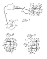
- the reference 10 generally identifies a carrier means or frame structure which carries a drill-unit generally identified at 11, said drill unit including a feed means for advancing or withdrawing a drill 12 through a given distance for each turn of said drill, in dependence on the direction of rotation of the drill 12.
- the reference 13 identifies a motor box which incorporates an electric motor (not shown in Figure 1) which via a reduction gear (not shown) and a flexible shaft 14 drives the drill unit 11 with associated feed means.
- an electric motor (not shown in Figure 1) which via a reduction gear (not shown) and a flexible shaft 14 drives the drill unit 11 with associated feed means.
- Connected to the electric motor located in the motor box 13 is one end of an electric cable 15, which is suitably several hundred meters long and which can be wound onto a cable drum 16 and through which operating current is supplied to the motor and also control and indicating signals.
- Control signals are also passed between the electric motor and the unit 11 via a cable 17 extending between said unit and said motor box 13, as will be described in more detail hereinafter.
- the other end, 18, of the cable 15 is connected to the mains network or to a mobile electrical plant (not shown) via a control means 19, which in the illustrated embodiment is mounted on the cable drum 16.
- the frame structure 10 comprises a longitudinally extending tube 20 and transversely extending tubes 21, 22, 23, the centre tube 22 projecting outwardly substantially to one side of the tube 20, while the other two tubes 21, 23 project outwardly substantially to the other side of the tube 20.
- the tubes 20-23 are arranged to accommodate therein axially movable tubes 24, 25, 26 which can be locked in desired positions of displacement and which carry at one end thereof transverse sleeves 27, 28 for receiving a tube 29 ( Figure 1) forming part of a holding means for the drill unit 11, and for receiving tubes 30 forming legs for the frame structure.
- the tubes 30 can be locked in desired axial positions in respective sleeves by means of locking screws 31, while the tubes 24 and 29 can be locked in desired axial positions and positions of rotation in associated tube 20 and sleeve 27 respectively.
- the tubes 25 and 26 are provided with a plurality of holes 32 distributed along their lengths, while the tubes 21 and 23 are provided at the ends thereof with holes 33.
- a selected hole 32 is placed opposite one of the holes 33 and a locking pin 34 is passed through the thus registered holes 32, 33.
- the tube 26 is provided with holes 32 distributed along the length of said tube .
- an externally screw-threaded sleeve 35 which can be moved axially along the tube 26 and which can be locked against axial and radial movement by means of a locking pin 36 which passes through a radial.hole in the sleeve 35 and a selected hole 32 in the tube 26.
- Screwed onto the sleeve 35 is an internally screw-threaded sleeve 37 which is arranged to abut the adjacent end of the tube 22.
- the frame structure 10 is arranged to be fixed in a desired position relative to an explosive object, such as a bomb or the like, to be disarmed, as shown at 38 in Figures 1 and 2 and at 39 in Figure 3 respectively.
- the frame structure can be adapted to the size of the object 38 or 39 by inserting the tubes 25, 26 into associated tubes 21, 22 or 23, from one direction or the other, and locking the legs 30 and the tubes 25 and the sleeve 35 in positions in which the tubes 30 are located adjacent said object.
- the sleeve 37 is screwed towards the adjacent end of the tube 22, until the object 38 or 39 is clamped between the frame legs formed by tubes 30 located on opposite sides of said object.
- the tube 29 carries on the end thereof projecting from sleeve 27 a fitting 40 which embraces and holds the drill unit 11,
- the fitting 40 is connected to the tube 29 via a pivot means 41 which permits the fitting to rotate, and therewith the drill unit 11, about an axis extending at right angles to the drilling direction, and to be locked in a desired position of rotation.
- the reference 42 in Figure 1 identifies a casing for a detonating fuse or the like, through the wall of which casing a hole is to be drilled at a predetermined location and in a predetermined direction.
- the position of the drill unit 11 is set to enable a hole to be drilled in the aforesaid manner, by adjusting the axial and rotary positions of the tubes 24 and 29, and the rotary position of the pivot means 41.
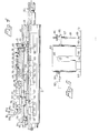
- the drill unit which is illustrated in more detail in Figure 4, includes a casing comprising parts 43, 44, 45 and 46, in which casing there is carried, by means of bearings 47, 48 and 49, an input part 50 driven via the flexible shaft 14 (Figure 1), and a drill-holding part 51 for holding the drill 12 ( Figure 1).
- the input part 50 which is rotatably mounted by means of bearings 47, 48, is immovable axially and accomodates the inner end part of the drill-holding part 51 in a cylindrical bore 52, said drill-holding part 51 having at its opposite end a chuck structure 53.
- the drill-holding part 51 is mounted for rotation and for axial movement in the bearing 49 and is also journalled for axial movement in the bore 52 of the.. part 50.
- a screw having a cylindrical head 54 which is accomodated in a slot 55, having a width conforming.thereto, in the part 50.
- the screw head 54 projects radially somewhat beyond the part 50, and the outermost part of the head 54 is accomodated in a peripherally extending internal groove 56 in a sleeve 57 which is mounted for rotational and axial movement relative to the outer surface of the part 50.
- a gear means which is operative between said parts 50, 51 and which includes two gear wheels 58 and 59 which surround the drill-holding part and which are held at a constant distance apart by means of a spacing sleeve 60.
- the side of the gear wheel 58 remote from the spacing sleeve 60 abuts the end of the casing part 46 via two spacing means 61, while the other gear wheel 59 abuts the forward end of the input part 50.
- the gear wheel 58 is coupled to the drill-holding part by means of a groove 62 arranged in the drill-holding part 51 and a key 63 in a manner such that while the gear wheel 58 can move axially it is locked against rotation relative to the part 51.
- the other gear wheel 59 has an internal screwthread and is in thread engagement with an external screw thread 64 arranged on the drill-holding part 51.
- Each of the gear wheels 58, 59 meshes with a further respective gear wheel 65, 66 which is fixedly connected to a shaft 67 which extends substantially parallel to the axis of rotation of the parts 50, 51 and which is rotatably mounted in a journal block 68 which is held in a desired position in the casing part 45 by means of setting screws 69 and locking screws 70.
- the ratio of the number of teeth of the gear wheel 58 to the gear wheel 65 so differs from the ratio of the number of teeth of gear wheel 59 to gear wheel 66 that when rotating the parts 50, 51 in the intended drilling direction, the gear wheel 59 is screwed along the drill-holding part towards the input part 50, so that the part 51 is fed to the right as seen in Figure 4 relative to the casing 43-46 through a distance dependent upon the number of turns made by the drill, and when rotating the parts 50, 51 in the opposite direction is screwed along the drill-holding part 51 away from the input part 50, so that the part 51 is withdrawn inwardly into the bore 52 of the input part to an extent dependent on the number of turns made by the drill.
- said sleeve, and therewith also the screw 71, 72 will move along the input part 50 in the same manner of axial movement as the drill-holding part 51.
- Arranged on the frame part 44 are two attachment means 74, 75, between which there extends a part 76 provided with a scale, and an indicator 77 is arranged on the screw-head 72 to enable the position of the drill-holding part 51 relative to the input part 50 to be readily observed.
- a rod 78 Extending between the attachment means 74, 75 is a rod 78 one end of which is mounted for axial movement in the attachment means 74, and the other end of which is secured in a switch-actuating body 79, via which the rod is also journalled for axial movement in the attachment means 75.
- the rod 78 extends through a diagonal slot in the screw-head 72 and carries two stops 80, which can be fixed in selected positions along the rod and via which the screw-head 72 can displace the rod 78, and therewith the body 79, axially.
- the body 79 is arranged to actuate a switch 81 having a stationary contact element 81a, and two movable contact elements 81b and 81c which can be swung outwardly by means of the body 79 when said body moves in the directions illustrated by the double-headed arrow 82 to the positions shown in broken lines, in which positions said movable contact elements are out of contact with the stationary contact element 81a.
- FIG. 5 illustrates an electric motor for driving the drill unit 11.
- the electric motor is shown in rear view and is incorporated in the motor box 13, shown at the bottom of the Figure, and has a motor housing 83.
- the motor housing is carried by carrier means 84 in a manner such as to permit the housing to rotate about a shaft 85 extending co-axially with the motor shaft.
- the motor housing 83 carries a lug 86 through which there extends an axially movable screw means 87, one end of which is connected to an attachment means 89 on the motor box 13 via a tension spring 88.
- a switch-actuating means 91 Projecting from the side of the motor housing 83 opposite the lug 86 is a switch-actuating means 91 which is arranged to break a switch 92 when the motor housing 83 is rotated anti-clockwise from the position shown in Figure 5. Rotation of the motor housing 83 is restricted by means of stop means 93.
- the motor shaft is arranged to rotate in a clockwise direction when the drill 12 is driven in its working direction. When , in this case, the motor shaft rotates clockwise, the motor housing 83 will strive to rotate anti-clockwise , due to the reaction forces created.
- the spring force exerted by the tension spring 88 and acting in a direction opposite to said reaction forces is set with the aid of the nut 90, so that in the position illustrated in Figure 5 the spring force is able to balance the reaction force only when the drill 12 does carry out work with the drive motor running.
- the reaction force increases, as occurs when a greater torque is taken from the motor as the drill 12 carries out work, the motor housing 83 is turned anti-clockwise, whereat the switch-actuating means 91 will move the switch 92 to a circuit-breaking state.
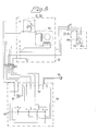
- the switch 92 is incorporated in a current circuit which includes a signalling means 94 in the form of a lamp which is arranged on the control means 19 and which will thus be extinguished when the drill 12 works and illuminated as soon as the tip of the drill 12 has broken through the wall of the detonating fuse casing 42 illustrated in Figure 1.
- Figure 6 illustrates the control means 19, which is supplied , via an electric plug 18, with current from an a.c. source (not shown) and which includes the signal means 94 and a selector switch 95 by means of which drive and control current can be broken (position "O") and closed either for driving the drill 12 in its working direction and advancing the same (position "1"), or for rotating the drill 12 in the opposite direction and withdrawing the drill (position "2").
- Figure 6 also illustrates the motor box 13 with the schematically illustrated motor 96 and the switch means 91, 92 and 79, 81 respectively.
Landscapes
- Engineering & Computer Science (AREA)
- Mechanical Engineering (AREA)
- Manufacturing & Machinery (AREA)
- General Engineering & Computer Science (AREA)
- Drilling And Boring (AREA)
- Perforating, Stamping-Out Or Severing By Means Other Than Cutting (AREA)
- Earth Drilling (AREA)
Applications Claiming Priority (2)
| Application Number | Priority Date | Filing Date | Title |
|---|---|---|---|
| US279815 | 1981-07-02 | ||
| US06/279,815 US4431350A (en) | 1981-07-02 | 1981-07-02 | Disarming apparatus |
Publications (2)
| Publication Number | Publication Date |
|---|---|
| EP0069716A2 true EP0069716A2 (de) | 1983-01-12 |
| EP0069716A3 EP0069716A3 (de) | 1983-09-14 |
Family
ID=23070523
Family Applications (1)
| Application Number | Title | Priority Date | Filing Date |
|---|---|---|---|
| EP82850142A Withdrawn EP0069716A3 (de) | 1981-07-02 | 1982-06-23 | Vorrichtung zum Entschärfen von Explosionskörpern |
Country Status (2)
| Country | Link |
|---|---|
| US (1) | US4431350A (de) |
| EP (1) | EP0069716A3 (de) |
Families Citing this family (6)
| Publication number | Priority date | Publication date | Assignee | Title |
|---|---|---|---|---|
| US7070365B1 (en) * | 2002-04-10 | 2006-07-04 | George R. Blankenship | Drill bit assembly for bomb deactivation and other applications |
| US6899007B1 (en) * | 2002-04-10 | 2005-05-31 | George R. Blankenship | Self-contained mobile chassis for bomb deactivation |
| WO2009117836A1 (en) * | 2008-03-28 | 2009-10-01 | Quanser Consulting Inc. | Drill assembly and method to reduce drill bit plunge |
| US8141468B2 (en) | 2009-03-17 | 2012-03-27 | Raytheon Company | Adjustable bomb carrier |
| US10254076B2 (en) * | 2015-07-31 | 2019-04-09 | John Francis Penrod | Apparatus for use with a disrupter to disable explosive ordnance and improvised explosive devices |
| US12281886B2 (en) * | 2022-01-05 | 2025-04-22 | Federal Bureau Of Investigation | Methods for rendering safe devices containing explosives |
Family Cites Families (5)
| Publication number | Priority date | Publication date | Assignee | Title |
|---|---|---|---|---|
| US2910895A (en) * | 1957-12-13 | 1959-11-03 | James C Winslow | Power tool with suction foot |
| US2997900A (en) * | 1959-11-09 | 1961-08-29 | Lawrence E Pugsley | Multipurpose tool fixture |
| US3088341A (en) * | 1961-08-15 | 1963-05-07 | Roman-Garcia Carlos | Universal drill press |
| JPS5531542A (en) * | 1978-08-23 | 1980-03-05 | Akashi Seisakusho Co Ltd | Abnormality detecting system for tool or work in machine tool |
| US4310269A (en) * | 1980-02-19 | 1982-01-12 | Northrop Corporation | Drill break-through sensor |
-
1981
- 1981-07-02 US US06/279,815 patent/US4431350A/en not_active Expired - Fee Related
-
1982
- 1982-06-23 EP EP82850142A patent/EP0069716A3/de not_active Withdrawn
Also Published As
| Publication number | Publication date |
|---|---|
| EP0069716A3 (de) | 1983-09-14 |
| US4431350A (en) | 1984-02-14 |
Similar Documents
| Publication | Publication Date | Title |
|---|---|---|
| EP0229399B1 (de) | Einrichtung zur drahtlosen Übertragung von Signalen von einem rotierenden Körper | |
| US6446519B1 (en) | Electric actuator | |
| US4604005A (en) | Portable selector drill | |
| US4431350A (en) | Disarming apparatus | |
| US2617971A (en) | Overload control for motors | |
| GB2401440A (en) | Servo motor with an encoder and nonvolatile memory for storing positional data. | |
| GB2098635A (en) | Tensioning apparatus for sewing machines | |
| US4705440A (en) | Tool holder for milling or boring machine | |
| GB1571322A (en) | Screw feed for machine tools | |
| EP0063460A2 (de) | Motorgetriebenes Gerät | |
| US2590420A (en) | Toolhead with adjustment indicator | |
| US4202110A (en) | Theodolite tangent screw system | |
| US3627437A (en) | Toolholder detection system | |
| US6354776B1 (en) | Electric drive spindle | |
| US4762037A (en) | Face and internal turning head | |
| US2774261A (en) | Control mechanism for drill presses | |
| GB1594233A (en) | Electrical controls for multispindle lathes | |
| KR0149784B1 (ko) | Cnc 선반의 공작물 회수장치 | |
| CN117888794A (zh) | 一种平开门机 | |
| EP2308640B1 (de) | Abfragesystem für eine bewegte Maschinenkomponente | |
| US2439965A (en) | Drill press | |
| RU2057929C1 (ru) | Буровой станок | |
| SU1140108A1 (ru) | Механизм ограничени угла поворота | |
| RU2309821C1 (ru) | Устройство сверлильно-фрезерное усф | |
| SU625857A1 (ru) | Устройство дл нарезани резьбы метчиком на револьверном станке |
Legal Events
| Date | Code | Title | Description |
|---|---|---|---|
| PUAI | Public reference made under article 153(3) epc to a published international application that has entered the european phase |
Free format text: ORIGINAL CODE: 0009012 |
|
| AK | Designated contracting states |
Designated state(s): BE DE FR GB IT NL |
|
| PUAL | Search report despatched |
Free format text: ORIGINAL CODE: 0009013 |
|
| AK | Designated contracting states |
Designated state(s): BE DE FR GB IT NL |
|
| 17P | Request for examination filed |
Effective date: 19840306 |
|
| STAA | Information on the status of an ep patent application or granted ep patent |
Free format text: STATUS: THE APPLICATION IS DEEMED TO BE WITHDRAWN |
|
| 18D | Application deemed to be withdrawn |
Effective date: 19850528 |