EP0069655A1 - High sensitivity differential protection device for the detection of earthed phase or neutral fault currents - Google Patents
High sensitivity differential protection device for the detection of earthed phase or neutral fault currents Download PDFInfo
- Publication number
- EP0069655A1 EP0069655A1 EP82401230A EP82401230A EP0069655A1 EP 0069655 A1 EP0069655 A1 EP 0069655A1 EP 82401230 A EP82401230 A EP 82401230A EP 82401230 A EP82401230 A EP 82401230A EP 0069655 A1 EP0069655 A1 EP 0069655A1
- Authority
- EP
- European Patent Office
- Prior art keywords
- voltage
- comparator
- generator
- secondary winding
- protection device
- Prior art date
- Legal status (The legal status is an assumption and is not a legal conclusion. Google has not performed a legal analysis and makes no representation as to the accuracy of the status listed.)
- Granted
Links
Images


Classifications
-
- H—ELECTRICITY
- H02—GENERATION; CONVERSION OR DISTRIBUTION OF ELECTRIC POWER
- H02H—EMERGENCY PROTECTIVE CIRCUIT ARRANGEMENTS
- H02H3/00—Emergency protective circuit arrangements for automatic disconnection directly responsive to an undesired change from normal electric working condition with or without subsequent reconnection ; integrated protection
- H02H3/26—Emergency protective circuit arrangements for automatic disconnection directly responsive to an undesired change from normal electric working condition with or without subsequent reconnection ; integrated protection responsive to difference between voltages or between currents; responsive to phase angle between voltages or between currents
- H02H3/32—Emergency protective circuit arrangements for automatic disconnection directly responsive to an undesired change from normal electric working condition with or without subsequent reconnection ; integrated protection responsive to difference between voltages or between currents; responsive to phase angle between voltages or between currents involving comparison of the voltage or current values at corresponding points in different conductors of a single system, e.g. of currents in go and return conductors
- H02H3/33—Emergency protective circuit arrangements for automatic disconnection directly responsive to an undesired change from normal electric working condition with or without subsequent reconnection ; integrated protection responsive to difference between voltages or between currents; responsive to phase angle between voltages or between currents involving comparison of the voltage or current values at corresponding points in different conductors of a single system, e.g. of currents in go and return conductors using summation current transformers
- H02H3/332—Emergency protective circuit arrangements for automatic disconnection directly responsive to an undesired change from normal electric working condition with or without subsequent reconnection ; integrated protection responsive to difference between voltages or between currents; responsive to phase angle between voltages or between currents involving comparison of the voltage or current values at corresponding points in different conductors of a single system, e.g. of currents in go and return conductors using summation current transformers with means responsive to dc component in the fault current
-
- H—ELECTRICITY
- H02—GENERATION; CONVERSION OR DISTRIBUTION OF ELECTRIC POWER
- H02H—EMERGENCY PROTECTIVE CIRCUIT ARRANGEMENTS
- H02H3/00—Emergency protective circuit arrangements for automatic disconnection directly responsive to an undesired change from normal electric working condition with or without subsequent reconnection ; integrated protection
- H02H3/26—Emergency protective circuit arrangements for automatic disconnection directly responsive to an undesired change from normal electric working condition with or without subsequent reconnection ; integrated protection responsive to difference between voltages or between currents; responsive to phase angle between voltages or between currents
- H02H3/32—Emergency protective circuit arrangements for automatic disconnection directly responsive to an undesired change from normal electric working condition with or without subsequent reconnection ; integrated protection responsive to difference between voltages or between currents; responsive to phase angle between voltages or between currents involving comparison of the voltage or current values at corresponding points in different conductors of a single system, e.g. of currents in go and return conductors
- H02H3/33—Emergency protective circuit arrangements for automatic disconnection directly responsive to an undesired change from normal electric working condition with or without subsequent reconnection ; integrated protection responsive to difference between voltages or between currents; responsive to phase angle between voltages or between currents involving comparison of the voltage or current values at corresponding points in different conductors of a single system, e.g. of currents in go and return conductors using summation current transformers
- H02H3/331—Emergency protective circuit arrangements for automatic disconnection directly responsive to an undesired change from normal electric working condition with or without subsequent reconnection ; integrated protection responsive to difference between voltages or between currents; responsive to phase angle between voltages or between currents involving comparison of the voltage or current values at corresponding points in different conductors of a single system, e.g. of currents in go and return conductors using summation current transformers responsive to earthing of the neutral conductor
Definitions
- the known protective devices against earth fault currents generally use a differential zero sequence transformer with toroidal core whose primary windings are traversed by the currents of the conductors of the electrical installation to be protected.
- the secondary winding provides a differential fault signal when the sum of the currents flowing through the primary windings is not zero. This signal is applied to the control coil of the trip relay of a protective circuit breaker.
- An electronic amplification device can be inserted between the zero sequence transformer and the trip relay to fix the trip threshold. It is then possible to detect phase-to-earth faults of the order of 10 mA.
- the detection of a neutral earth fault downstream of the fault detection system is carried out in a conventional manner by means of two toroids, the first of which is associated with a high frequency oscillator, which induces a high frequency current in the loop constituted by the neutral - earth fault, the second toroid of which comprises the secondary control winding cooperating with the tripping circuit.
- This device requires two toroids and is not sensitive to continuous phase-to-earth fault currents.
- the object of the present invention is to remedy these drawbacks and to allow the production of a single-core differential protection device capable of permanently detecting an earthing of the neutral and of the phase-to-earth AC or DC fault currents.
- the device according to the invention is characterized in that a generator G, with alternating output voltage U 2 of fixed frequency F greater than the frequency of the network, delivers a pilot current to the secondary winding L 1 of the toroid, and a threshold comparator locates the variation in the amplitude of the voltage U 1 at the terminals of the secondary winding L 1 or L 2 by comparing it with a reference voltage. It is noted that the appearance of any fault current, in particular by earthing the neutral or phase - alternating and continuous earth - leads to a modification of the magnetic state of the single toroid and a decrease in the voltage U 1 at terminals of the secondary winding L 1 or L 2 . This results in an increase in the differential voltage at the output of the comparator. If this differential voltage exceeds a predetermined threshold, the switching device is released and the relay triggers the circuit breaker.
- the generator G of frequency F is arranged to deliver a constant output voltage U 2 which serves as a reference voltage to the comparator.
- the circuit for connecting the generator G to the secondary winding L 1 includes a resistor whose value is chosen to impose a pilot current of substantially constant intensity.
- each input of the comparator is respectively connected to the generator G and to the secondary winding L 1 or L 2 of the toroid by a rectification circuit comprising a rectifier in series with a filter.
- the alternating voltage U 1 of the secondary winding L 1 of the toroid is applied to an auxiliary comparator by means of a first positive alternation discriminator and a second alternation discriminator negative, said comparator being arranged to compare the amplitudes of the two positive and negative half-waves of the voltage U 1 , one of the half-waves being modified when a phase-earth alternating or continuous fault current occurs while the other remains fixed.
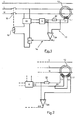
- FIG. 1 shows a highly sensitive differential protection device 10 for detecting earth faults in a low-voltage single-phase alternating network with L phase, N neutral and T earth conductors.
- the device 10 is interposed between the main power source and the receiver and comprises a ferromagnetic torus 12 crossed by the phase L and neutral N conductors, which form the primary windings of the torus 12.
- a secondary winding L 1 is wound on the torus 12 and is connected to a measurement and processing circuit 14 capable of delivering a trip order to a relay 16 for actuating a circuit breaker 16 of protection.
- the latter is connected to the conductors L and N upstream of the toroid 12 in the direction of the power source to interrupt the supply of the installation in the event of an earth fault detected by the differential transformer with toroid 12.
- the conductor neutral 11 is connected to earth upstream of circuit breaker 18.
- the measurement and processing circuit 14 is supplied by an auxiliary source 20 with positive safety taken from the AC voltage of the distribution network.
- the secondary winding L 1 of the toroid 12 is connected to a generator G via a resistor 22.
- the generator G is formed by a sinusoidal oscillator with constant voltage U 2 and at fixed frequency F greater than the frequency 50 Hz of the distribution network.
- the oscillator is powered by the auxiliary source 20 and operates automatically when the circuit breaker 18 is closed, so as to deliver a high frequency pilot current in the secondary winding L 1 of the toroid 12.
- the value of the resistance 22 is sufficiently large to impose a constant pilot current.
- a threshold comparator 24 constituted by a differential amplifier is connected to the terminals of the generator G and of the secondary winding L 1 of the torus 12. The output of the comparator 24 controls a switching member 26 connected in series with the relay 16 and the auxiliary source 20.
- the high-frequency generator G permanently generates a pilot current of constant intensity in the secondary winding L 1 of the torus 12.
- the comparator 24 compares the voltages U 2 and U 1 at the terminals of the generator G and of the winding L 1 , the fixed voltage U 2 serving as a reference ( Figure 6a). In the absence of a fault, the voltages U 2 and U 1 are substantially equal and the comparator 24 indicates a very small or zero difference incapable of causing the conduction of the switching member 26 and the excitation of the relay 16.
- a differential transformer with a single torus 12 is sufficient to detect the three types of earth faults thanks to the comparator 24 which locates the variation of the voltage U 1 at the terminals of the winding L 1 by comparing it with a reference voltage U 2 delivered by the high frequency generator G associated with the torus 12.
- Figure 2 is a variant of the differential protection device according to Figure 1, the torus 12 being provided with two separate secondary windings L 1 and L 2 .
- the winding L 1 is connected to the high-frequency generator G in series with the resistor 22 while the winding L 2 is connected to an input of the comparator 24 and to a common point 30 for connection of the winding L 1 .
- the comparator 24 then compares the amplitude of the voltage U 1 at the terminals of the winding L 2 with respect to that of the reference voltage U 2 of the generator G.
- the sequence of operation is similar to that of the device in FIG. l.
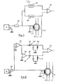
- FIG. 3 corresponds to the assembly of FIG. 1, with a single secondary winding L 1 .
- the comparison of the voltages U 2 of the generator G and U l of the winding L 1 is fcctue in instant thanks to a circuit R 1 C 1 series connected between the generator G and an input of the comparator 24.
- a resistor R 2 is connected between the winding L 1 and the other input of the comparator 24, the two resistors R 1 and R 2 being adjustable to adjust, in the absence of a fault, the comparator input voltages 24.
- the comparator 24 output is connected to a high-pass filter 32 connected to the switching member 26 via a threshold circuit 34.
- the operation of the device of FIG. 3 is identical to that of FIG. 1.
- Fig. 4 is a variant of FIG.
- the generator G is connected by a connecting conductor 38 to an impedance adapter 40 in series with a rectifier 42 and a filtering circuit 44 with capacity resistance, connected to one of the inputs of the comparator 24.
- the secondary winding L 1 of the toroid 12 is connected in the same way by a conductor 45 to the other input of the comparator 24 via a series circuit comprising an impedance adapter 46, a rectifier 48 and a filter 50. At rest the difference between the rectified voltages U 2 and U 1 is zero, and the comparator 24 does not deliver any signal. In the presence of an earth fault, the voltage U 1 decreases, and the output of comparator 24 indicates a control differential voltage ⁇ U.
- the amplitude of the voltage U 1 of the secondary winding L 1 or L 2 of the toroid 12 can be affected by the temperature of the torus 12.
- the temperature drift is indeed quite important for continuous or alternating phase-to-earth faults as soon as the temperature of the magnetic material of the torus 12 reaches 40 ° C.
- This drift is linked to the variation in the permeability of the material with the temperature causing a corresponding variation in the voltage U 1 at the terminals of the winding L 1 of the toroid 12 while the reference voltage U 2 of the generator G remains constant.
- the balance differential is thus destroyed even in the absence of a fault. and may cause nuisance trips.
- the use of a predetermined material with substantially constant permeability as a function of the temperature would make it possible to avoid these nuisance trips.
- Another means of reducing the temperature drift consists in modifying the signal processing circuit taken at the terminals of the winding L 1 of the torus 12. It can be seen in FIG. 8b that a continuous phase-earth fault only affects 'only one of the two half-waves of the voltage U 1 . notably positive alternation, while the amplitude of negative alternation remains constant before and after the instant of the fault. The same is true for an AC phase-to-earth fault at 50 Hz.
- FIG. 5 instead of taking the voltage U 2 of the high-frequency generator G as a reference, it suffices to compare the amplitudes of the two positive and negative half-waves of the voltage U 1 between them at the terminals of the secondary winding L 1. , one of them remaining in effect constant by way of reference.
- the generator G at high frequency F delivers, as previously, a constant pilot current to the winding L 1 of the detection toroid 12.
- the voltage U 1 is applied to a first discriminator 52 of positive half-waves and to a second discriminator 54 of negative half-waves whose outputs are connected to the inputs of a comparator 56.
- the two half-waves of the voltage U 1 are equal, and no signal is delivered by the comparator 56 independently of the variations in the permeability of the toroid 12 with the temperature.
- the amplitudes of the two half-waves are unequal and the comparator 56 delivers a trigger signal.
- FIG. 6 represents an embodiment of the block diagram indicated in FIG. 5. The same references will be used to designate identical or similar components.
- the voltage U 1 at the terminals of the winding L 1 of the toroid 12 is applied to an impedance adapter 60 formed by an operational gain amplifier 1.
- the output of the adapter 60 is connected on the one hand to the first discriminator 52 of positive alternations constituted by a diode rectifier 62 and a filtering circuit 64, and on the other hand to the second discriminator 54 of negative alternations formed by a polarity inverter 66 in series with a diode rectifier 68 and a circuit filtering 70.
- the two filtered rectified voltages e + are then applied to the inputs of comparator 56 which delivers in the event of an AC or DC phase-to-earth fault a differential trigger control voltage.
- the two half-waves of the voltage U 1 are also affected by the variation in permeability and the effect of the temperature is zero as in the circuit of FIG. 5.
- the device of FIG. 7 supplements that of FIG. 5 by ensuring both the detection of the neutral earth fault and of the alternating or continuous phase - earth fault.
- a first processing circuit 74 identical to that of FIG. 5 compares the amplitudes of the two half-waves of the voltage U 1 across the terminals of L 1 .
- Circuit 74 detects phase-to-earth faults.
- a second processing circuit 76 is constituted by the conventional comparator 24 of FIGS. 1 to 4, which compares the voltage U 1 at the terminals of the winding L 1 with that U 2 delivered by the generator G. This circuit 76 detects the neutral fault To the earth.
- the two outputs of the comparators 24 and 56 are connected to an OR logic circuit 78, which takes into account the information coming from the two circuits
- the invention has been described as applying to a single-phase alternating network, but it is obvious that the various characteristics are also applicable to a multi-pole network, in particular three-phase with neutral.
- the invention extends to any other variant remaining within the framework of electronic and electrotechnical equivalences.
Abstract
Description
L'invention est relative à un dispositif de protection différentielle pour la détection de courants de défaut à la terre dans une installation électrique alimentée par un réseau à courant alternatif: et comprenant :
- - un transformateur différentiel ayant un noyau magnétique à tore unique traversé par les conducteurs de phase L et neutre N du réseau formant les enroulements primaires du transformateur,
- - au moins un enroulement secondaire L1 ou L2 bobiné sur le tore et coopérant avec un circuit de mesure et de traitement susceptible de délivrer après dépassement d'un seuil prédéterminé, un ordre de drclenchement à une bobine de commande d'un appareil de coupure lors de l'apparition d'un courant de défaut à la terre,
- - et un circuit auxiliaire d'alimentation du circuit de mesure et de traitement.
- - a differential transformer having a single core magnetic core crossed by the phase L and neutral N conductors of the network forming the primary windings of the transformer,
- - at least one secondary winding L 1 or L 2 wound on the toroid and cooperating with a measurement and processing circuit capable of issuing, after exceeding a predetermined threshold, a triggering order to a control coil of an apparatus for cut off when an earth fault current appears,
- - And an auxiliary power supply circuit for the measurement and processing circuit.
Les dispositifs de protection connus contre les courants de défaut à la terre utilisent généralement un transformateur homopolaire différentiel à noyau torique dont les enroulements primaires sont parcourus par les courants des conducteurs de l'installation électrique à protéger. L'enroulement secondaire fournit un signal de défaut différentiel lorsque la somme des courants parcourant les enroulements primaires n'est pas nulle. Ce signal est appliqué à la bobine de commande du relais de déclenchement d'un disjoncteur de protection.The known protective devices against earth fault currents generally use a differential zero sequence transformer with toroidal core whose primary windings are traversed by the currents of the conductors of the electrical installation to be protected. The secondary winding provides a differential fault signal when the sum of the currents flowing through the primary windings is not zero. This signal is applied to the control coil of the trip relay of a protective circuit breaker.
Un dispositif électronique d'amplification peut être intercalé entre le transformateur homopolaire et le relais déclencheur pour fixer le seuil de déclenchement. Il est alors possible de détecter des défauts phase-terre de l'ordre de 10 mA.An electronic amplification device can be inserted between the zero sequence transformer and the trip relay to fix the trip threshold. It is then possible to detect phase-to-earth faults of the order of 10 mA.
L'utilisation d'un transformateur homopolaire présente néanmoins des inconvénients lorsqu'il s'agit de détecter des courants de défaut phase - terre continu ou à composante continue. On a remarqué que le seuil de déclenchement est affecté par la présence d'un courant ou d'une composante continue. Cette variation du seuil provoque une désensibilisation de la protection par tore à haute perméabilité. L'utilisation d'un tore spécial doté d'un matériau magnétique prédéterminé à cycle étroit et penché permet de pallier cet inconvénient. Il est également possible d'utiliser un tore classique dont l'enroulement secondaire est associé à un filtre de mise en forme qui permet de conserver un même seuil de déclenchement en régime de courant alternatif ou continu. Ces dispositifs connus ne permettent généralement pas la détection du défaut neutre à la terre. Ce type de défaut désensibilise et peut même aveugler totalement la protection différentielle.The use of a zero sequence transformer nevertheless has drawbacks when it comes to detecting phase-to-earth fault currents or DC component currents. It has been noted that the triggering threshold is affected by the presence of a current or of a continuous component. This variation of the threshold causes desensitization of the protection by toroid with high permeability. The use of a special torus provided with a predetermined magnetic material with a narrow and tilted cycle overcomes this drawback. It is also possible to use a conventional toroid whose secondary winding is associated with a shaping filter which makes it possible to keep the same triggering threshold in alternating or direct current regime. These known devices generally do not allow the detection of a neutral earth fault. This type of fault desensitizes and can even completely blind the differential protection.
La détection du défaut neutre à la terre en aval du système de détection de défaut s'effectue d'une manière classique au moyen de deux tores dont le premier est associé à un oscillateur à haute fréquence, qui induit un courant à haute fréquence dans la boucle constituée par le défaut neutre - terre, et dont le deuxième tore comprend l'enroulement secondaire de commande coopérant avec le circuit de déclenchement. Ce dispositif nécessite deux tores et n'est pas sensible à des courants de défaut phase - terre continu.The detection of a neutral earth fault downstream of the fault detection system is carried out in a conventional manner by means of two toroids, the first of which is associated with a high frequency oscillator, which induces a high frequency current in the loop constituted by the neutral - earth fault, the second toroid of which comprises the secondary control winding cooperating with the tripping circuit. This device requires two toroids and is not sensitive to continuous phase-to-earth fault currents.
La présente invention a pour but de remédier à ces inconvénients et de permettre la réalisation d'un dispositif de protection différentielle à tore unique pouvant détecter en permanence une mise à la terre du neutre et des courants de défaut phase - terre alternatif ou continu.The object of the present invention is to remedy these drawbacks and to allow the production of a single-core differential protection device capable of permanently detecting an earthing of the neutral and of the phase-to-earth AC or DC fault currents.
Le dispositif selon l'invention est caractérisé par le fait qu'un générateur G, à tension de sortie alternative U2 de fréquence F fixe supérieure à la réquence du réseau, délivre un courant pilote à l'enroulement secondaire L1 du tore, et qu'un comparateur à seuil repère la variation de l'amplitude de la tension U1 aux bornes de l'enroulement secondaire L1 ou L2 en la comparant à une tension de référence. On remarque que l'apparition d'un courant de défaut quelconque, notamment par mise à la terre du neutre ou phase - terre alternatif et continu, entraîne une modification de l'état magnétique du tore unique et une diminution de la tension U1 aux bornes de l'enroulement secondaire L1 ou L2. Il en résulte une augmentation de la tension différentielle à la sortie du comparateur. Si cette tension différentielle dépasse un seuil prédéterminé, l'organe de commutation est débloqué et le relais provoque le déclenchement du disjoncteur.The device according to the invention is characterized in that a generator G, with alternating output voltage U 2 of fixed frequency F greater than the frequency of the network, delivers a pilot current to the secondary winding L 1 of the toroid, and a threshold comparator locates the variation in the amplitude of the voltage U 1 at the terminals of the secondary winding L 1 or L 2 by comparing it with a reference voltage. It is noted that the appearance of any fault current, in particular by earthing the neutral or phase - alternating and continuous earth - leads to a modification of the magnetic state of the single toroid and a decrease in the voltage U 1 at terminals of the secondary winding L 1 or L 2 . This results in an increase in the differential voltage at the output of the comparator. If this differential voltage exceeds a predetermined threshold, the switching device is released and the relay triggers the circuit breaker.
Selon une caractéristique de l'invention, le générateur G de fréquence F est agencé pour délivrer une tension de sortie U2 constante qui sert de tension de référence au comparateur. Le circuit de connexion du générateur G à l'enroulement secondaire L1 comporte une résistance dont la valeur est choisie pour imposer un courant pilote d'intensité sensiblement constante.According to a characteristic of the invention, the generator G of frequency F is arranged to deliver a constant output voltage U 2 which serves as a reference voltage to the comparator. The circuit for connecting the generator G to the secondary winding L 1 includes a resistor whose value is chosen to impose a pilot current of substantially constant intensity.
Selon une autre caractéristique de l'invention, chaque entrée du comparateur est reliée respectivement au générateur G et à l'enroulement secondaire L1 ou L2 du tore par un circuit de redressement comprenant un redresseur en série avec un filtre.According to another characteristic of the invention, each input of the comparator is respectively connected to the generator G and to the secondary winding L 1 or L 2 of the toroid by a rectification circuit comprising a rectifier in series with a filter.
Selon une autre caractéristique de l'invention la tension alternative U1 de l'enroulement secondaire L1 du tore est appliquée à un comparateur auxiliaire par l'intermédiaire d'un premier discriminateur d'alternances positives et d'un deuxième discriminateur d'alternances négatives, ledit comparateur étant agencé pour comparer les amplitudes des deux alternances positive et négative de la tension U1, l'une des alternances étant modifiée lors de l'apparition d'un courant de défaut phase - terre alternatif ou continu pendant que l'autre reste fixe.According to another characteristic of the invention, the alternating voltage U 1 of the secondary winding L 1 of the toroid is applied to an auxiliary comparator by means of a first positive alternation discriminator and a second alternation discriminator negative, said comparator being arranged to compare the amplitudes of the two positive and negative half-waves of the voltage U 1 , one of the half-waves being modified when a phase-earth alternating or continuous fault current occurs while the other remains fixed.
D'autres avantages et caractéristiques ressortiront plus clairement de l'exposé qui va suivre de divers modes de réalisation de l'invention, donnés à titrp d'exemples non limitatifs et représentés aux dessins annexés, dans lesquels :
- la figure 1 est une vue schématique du dispositif de protection différentielle à tore unique selon l'invention;
- la figure 2 est une vue partielle d'une variante de la figure 1 dont le tore est équipé de deux enroulements secondaires;
- les figures 3 et 4 représentent deux modes de réalisation du dispositif selon la figure 1;
- la figure 5 montre un circuit synoptique détecteur de défaut phase -terre à tore unique insensible à l'effet de température;
- la figure 6 représente un mode de réalisation du circuit de la figure 5;
- la figure 7 montre le circuit synoptique d'un dispositif à tore unique insensible à la température pour la détection du neutre à la terre et d'un défaut phase - terre alternatif ou continu;
- Figure 1 is a schematic view of the single-core differential protection device according to the invention;
- Figure 2 is a partial view of a variant of Figure 1, the torus is equipped with two secondary windings;
- Figures 3 and 4 show two embodiments of the device according to Figure 1;
- FIG. 5 shows a block circuit phase-earth fault detector with a single torus insensitive to the temperature effect;
- Figure 6 shows an embodiment of the circuit of Figure 5;
- FIG. 7 shows the synoptic circuit of a single-core device insensitive to temperature for the detection of neutral to earth and of a phase - earth fault alternating or continuous;
la figure 8 représente l'allure des tensions en divers points du dispositif selon la nature du défaut:
- - Fig. 8a : tension U2 délivrée par le générateur G à fréquence F fixe supérieure à celle du réseau;
- - Fig. 8b : tension U1 aux bornes de l'enroulement secondaire L1 du tore avant et après un défaut phase - terre continu;
- - Fig. 8c : tension différentielle ΔU = U1 - U2 suite au défaut phase - terre continu;
- - Fig. 8d : tension différentielle ΔU suite à un défaut phase - terre alternatif 50 Hz;
- - 8e : tension différentielle ΔU suite à un défaut neutre à la terre.
- - Fig. 8a: voltage U 2 delivered by the generator G at a fixed frequency F greater than that of the network;
- - Fig. 8b: voltage U 1 at the terminals of the secondary winding L 1 of the toroid before and after a continuous phase-earth fault;
- - Fig. 8c: differential voltage ΔU = U 1 - U 2 following the phase-to-earth fault;
- - Fig. 8d: differential voltage ΔU following an AC phase-to-
earth fault 50 Hz; - - 8th: differential voltage ΔU following a neutral earth fault.
Sur la figure 1 est représenté un dispositif de protection différentielle 10 à haute sensibilité pour la détection de défauts à la terre dans un réseau alternatif monophasé à basse tension à conducteurs de phase L, de neutre N et de terre T. Le dispositif 10 est intercalé entre la source principale d'alimentation et le récépteur et comporte un tore 12 ferromagnétique traversé par les conducteurs de phase L et de neutre N, qui forment les enroulements primaires du tore 12. Un enroulement secondaire L1 est bobiné sur le tore 12 et est relié à un circuit de mesure et de traitement 14 susceptible de délivrer un ordre de déclenchement à un relais 16 d'actionnement d'un disjoncteur 16 de protection. Ce dernier est branché sur les conducteurs L et N en amont du tore 12 en direction de la source d'alimentation pour interrompre l'alimentation de l'installation en cas de défaut à la terre détecté par le transformateur différentiel à tore 12. Le conducteur de neutre 11 est connecté à la terre en amont du disjoncteur 18.FIG. 1 shows a highly sensitive
Le circuit de mesure et de traitement 14 est alimenté par une source auxiliaire 20 à sécurité positive prise sur la tension alternative du réseau de distribution. L'enroulement secondaire L1 du tore 12 est branché à un générateur G par l'intermédiaire d'une résistance 22. Le générateur G est formé par un oscillateur sinusoidal à tension constante U2 et à fréquence fixe F supérieure à la fréquence 50 Hz du réseau de distribution. L'oscillateur est alimenté par la source auxiliaire 20 et fonctionne automatiquement lors de la fermeture du disjoncteur 18, de manière à délivrer un courant pilote haute fréquence dans l'enroulement secondaire L1 du tore 12. La valeur de la résistance 22 est suffisamment grande pour imposer un courant pilote constant.The measurement and
Un comparateur 24 à seuil constitué par un amplificateur différentiel est branché aux bornes du générateur G et de l'enroulement secondaire L1 du tore 12. La sortie du comparateur 24 commande un organe de commutation 26 relié en série avec le relais 16 et la source auxiliaire 20.A
Le fonctionnement du dispositif de protection différentielle selon la figure 1 est le suivant, la figure 8 indiquant schématiquement la forme des signaux en différents points du circuit.The operation of the differential protection device according to Figure 1 is as follows, Figure 8 schematically indicating the shape of the signals at different points of the circuit.
Le générateur G à haute fréquence genère en permanence un courant pilote d'intensité constante dans l'enroulement secondaire L1 du tore 12. Le comparateur 24 compare les tensions U2 et U1 aux bornes du générateur G et de l'enroulement L1, la tension U2 fixe servant de référence (figure 6a). En l'absence de défaut, les tensions U2 et U1 sont sensihlement égales et le comparateur 24 indique une différence très faible ou nulle incapable de provoquer la conduction de l'organe de commutation 26 et l'excitation du relais 16.The high-frequency generator G permanently generates a pilot current of constant intensity in the secondary winding L 1 of the
L'apparition d'un défaut entraîne une modification de l'état maqnétique du tore 12 et une diminution de la tension U1 aux bornes de l'enroulement L1. Il en résulte une augmentation de la tension différentielle ΔU = U1 - U2 à la sortie du comparateur 24. Si cette tension différentielle dépasse un seuil prédéterminé l'organe de commutation 26 est débloqué et le relais 16 provoque le déclenchement du disjoncteur 18.The appearance of a fault causes a modification of the maqnetic state of the
En cas de défaut phase - terre continu ou à composante continue, le courant de défaut continu, qui traverse le tore provoque une modification de la perméabilité entraînant une diminution de la tension U1 aux bornes de l'enroulement L1 (voir figure 8b), et une augmentation de la tension différentielle ΔU (figure 8c).In the event of a phase-to-earth or continuous component fault, the continuous fault current flowing through the toroid causes a change in the permeability resulting in a reduction in the voltage U 1 across the winding L 1 (see Figure 8b) , and an increase in the differential voltage ΔU (FIG. 8c).
En cas de défaut phase - terre alternatif; un courant de défaut alternatif 50 Hz traverse le tore 12 qui par induction électromagnétique sur l'enroulement L1 assure une modulation en amplitude du signal de fréquence F donné par le générateur G. La tension différentielle ΔU (figure 8d) augmente à l'apparition du défaut alternatif mais est modulée en amplitude par le signal de défaut à 50 Hz.In the event of a phase-to-earth fault; an alternating fault current 50 Hz crosses the
En cas de défaut neutre - terre résultant d'une mise accidentelle du conducteur neutre N à la terre en aval du tore 12, l'impédance de l'enroulement secondaire L1 du tore 12 varie entraînant une diminution de la tension U1. La détection du défaut neutre - terre par variation d'impédance de l'enroulement L1 du tore 12 provoque à la sortie du comparateur 24 une tension différentielle ΔU sinusoïdale (figure 8e) de fréquence F et dont l'amplitude dépasse le seuil de déclenchement du disjoncteur 18 qui s'ouvreIn the event of a neutral - earth fault resulting from an accidental putting of the neutral conductor N to earth downstream of the
On remarque qu'un transformateur différentiel à tore 12unique est suffisant pour détecter les trois types de défauts la terre grâce au comparateur 24 qui repère la variation de la tension U1 aux bornes de l'enroulement L1 en la comparant à une tension de référence U2 délivrée par le générateur G à haute fréquence associé au tore 12.It is noted that a differential transformer with a
La figure 2 est une variante du dispositif de protection différentielle selon la figure 1, le tore 12 étant doté de deux enroulements secondaires L1 et L2 distincts. L'enroulement L1 est connecté au générateur G à haute fréquence en série avec la résistance 22 tandis que l'enroulement L2 est branché à une entrée du comparateur 24 et à un point commun 30 de raccordement de l'enroulement L1. Le comparateur 24 compare alors l'amplitude de la tension U1 aux bornes de l'enroulement L2 par rapport à celle de la tension de référence U2 du générateur G. La suite du fonctionnement est similaire à celui du dispositif de la fig.l.Figure 2 is a variant of the differential protection device according to Figure 1, the
La figure 3 correspond au montage de la fig. 1, avec un enroulement secondaire L1 unique. La comparaison des tensions U2 du générateur G et Ul de l'enroulement L1 s'ef- fcctue en instantané grâce à un circuit R1C1 série branché entre le générateur G et une entrée du comparateur 24. Une résistance R2 est reliée entre l'enroulement L1 et l'autre entrée du comparateur 24, les deux résistances R1 et R2 étant réglables pour ajuster en l'absence de défaut les tensions d'entrée du comparateur 24. La sortie du comparateur 24 est branchée à un filtre 32 passe haut connecté à l'organe de commutation 26 par l'intermédiaire d'un circuit à seuil 34. Le fonctionnement du dispositif de la fig. 3 est identique à celui de la fig. 1. La fig. 4 est une variante de la fig. 1 dans laquelle la comparaison des tensions U2 de référence du générateur et U1 de l'enroulement L1 du tore 12 s'effectue dans le comparateur 24 après redressement pour ne pas avoir à tenir compte des déphasages et des formes d'ondes. Le générateur G est connecté par un conducteur de liaison 38 à un adaptateur d'impédance 40 en série avec un redresseur 42 et un circuit de filtrage 44 à résistance capacité, relié à l'une des entrées du comparateur 24. L'enroulement secondaire L1 du tore 12 est branché de la même manière par un conducteur 45 à l'autre entrée du comparateur 24 par l'intermédiaire d'un circuit série comprenant un adaptateur d'impédance 46, un redresseur 48 et un filtre 50. Au repos la différence entre les tensions U2 et U1 redressées est nulle, et le comparateur 24 ne délivre aucun signal. En présence d'un défaut à la terre, la tension U1 diminue, et la sortie du comparateur 24 indique une tension différentielle ΔU de commande.FIG. 3 corresponds to the assembly of FIG. 1, with a single secondary winding L 1 . The comparison of the voltages U 2 of the generator G and U l of the winding L 1 is fcctue in instant thanks to a circuit R 1 C 1 series connected between the generator G and an input of the
On remarque dans les dispositifs des figures 1 à 4 que l'amplitude de la tension U1 de l'enroulement secondaire L 1 ou L 2 du tore 12 peut être affectée par la température du tore 12. La dérive en température est en effet assez importante pour des défauts phase - terre continu ou alternatif dès que la température du matériau magnétique du tore 12 atteint 40°C. Cette dérive est liée à la variation de la perméabilité du matériau avec la température provoquant une variation correspondante de la tension U1 aux bornes de l'enroulement L1 du tore 12 alors que la tension de référence U 2 du générateur G reste constante. L'équilibre différentiel est ainsi détruit même en l'absence de défaut. et risque d'engendrer des déclenchements intempestifs. L'utilisation d'un matériau prédéterminé à perméabilité sensiblement constante en fonction de la température permettrait d'éviter ces déclenchements intempestifs.Note in the devices of Figures 1 to 4 that the amplitude of the voltage U 1 of the secondary winding L 1 or L 2 of the toroid 12 can be affected by the temperature of the
Un autre moyen de réduction de la dérive en température consiste à modifier le circuit de traitement du signal prélevé aux bornes de l'enroulement L1 du tore 12. On observe sur la figure 8b qu'un défaut phase - terre continu n'affecte qu'une seule des deux alternances de la tension U1. notamment l'alternance positive, alors que l'amplitude de l'alternance négative reste constante avant et après l'instant du défaut. Il en est de même pour un défaut phase - terre alternatif à 50 Hz.Another means of reducing the temperature drift consists in modifying the signal processing circuit taken at the terminals of the winding L 1 of the
Selon la figure 5, au lieu de prendre comme référence la tension U2 du générateur G à haute fréquence, il suffit de comparer entre elles les amplitudes des deux alternances positive et négative de la tension U1 aux bornes de l'enroulement secondaire L1, l'une d'elles restant en effet constante en guise de référence. Le générateur G à haute fréquence F délivre comme précédemment un courant pilote constant à l'enroulement L1 du tore 12 de détection. La tension U1 est appliquée à un premier discriminateur 52 d'alternances positives et à un deuxième discriminateur 54 d'alternances négatives dont les sorties sont branchées aux entrées d'un comparateur 56. En absence de défaut phase - terre, les deux alternances de la tension U1 sont égales, et aucun signal n'est délivré par le comparateur 56 indépendamment des variations de la perméabilité du tore 12 avec la température. En cas de défaut, les amplitudes des deux alternances sont inégales et le comparateur 56 délivre un signal de déclenchement.According to FIG. 5, instead of taking the voltage U 2 of the high-frequency generator G as a reference, it suffices to compare the amplitudes of the two positive and negative half-waves of the voltage U 1 between them at the terminals of the secondary winding L 1. , one of them remaining in effect constant by way of reference. The generator G at high frequency F delivers, as previously, a constant pilot current to the winding L 1 of the
La figure 6 représente un mode de réalisation du schéma de principe indiqué à la fig. 5. Les mêmes repères seront utilisés pour désigner des composants identiques ou similaires.FIG. 6 represents an embodiment of the block diagram indicated in FIG. 5. The same references will be used to designate identical or similar components.
La tension U1 aux bornes de l'enroulement L1 du tore 12 est appliqué à un adaptateur d'impédance 60 formé par un amplificateur opérationnel de gain 1. La sortie de l'adaptateur 60 est reliée d'une part au premier discriminateur 52 d'alternances positives constitué par un redresseur à diode 62 et un circuit de filtrage 64, et d'autre part au deuxième discriminateur 54 d'alternances négatives formé par un inverseur de polarité 66 en série avec un redresseur à diode 68 et un circuit de filtrage 70. Les deux tensions redressées e+ filtrées sont ensuite appliquées aux entrées du comparateur 56 qui délivre en cas de défaut phase - terre alternatif ou continu une tension différentielle de commande de déclenchement. En l'absence de défaut phase - terre, les deux alternances de la tension U1 sont affectées également par la variation de perméabilité et l'effet de-la température est nul comme dans le circuit de la fig. 5.The voltage U 1 at the terminals of the winding L 1 of the
On remarque que le défaut neutre à la terre qui provoque une variation égale de l'amplitude des deux alternances de la tension U1 n'est pas détecté par les circuits des fig. 5 ou 6.It is noted that the neutral earth fault which causes an equal variation in the amplitude of the two half-waves of the voltage U 1 is not detected by the circuits of FIGS. 5 or 6.
Le dispositif de la figure 7 complète celui de la figure 5 en assurant à la fois la détection du défaut neutre à la terre et du défaut phase - terre alternatif ou continu. A partir du circuit pilote formé par le générateur G à haute fréquence, la résistance 22 et le bobinage secondaire L1 du tore 12, un premier circuit de traitement 74 identique à celui de la figure 5, compare entre elles les amplitudes des deux alternances de la tension U1 aux bornes de L1. Le circuit 74 détecte les défauts phase - terre. Un deuxième circuit de traitement 76 est constitué par le comparateur 24 classique des figures 1 à 4, qui compare la tension U1 aux bornes de l'enroulement L1 avec celle U2 délivrée par le générateur G. Ce circuit 76 détecte le défaut neutre à la terre. Les deux sorties des comparateurs 24 et 56 sont reliées à un circuit logique OU 78, qui prend en compte les informations en provenance des deux circuitsThe device of FIG. 7 supplements that of FIG. 5 by ensuring both the detection of the neutral earth fault and of the alternating or continuous phase - earth fault. From the pilot circuit formed by the high-frequency generator G, the
de traitement 74, 76 pour envoyer un ordre de déclenchement en cas d'apparition d'un quelconque défaut phase - terre ou neutre à la terre.74, 76 to send a trip order in the event of any phase-to-earth or earth-neutral fault.
L'invention a été décrite comme s'appliquant à un réseau alternatif monophasé, mais il est évident que les diverses caractéristiques sont également applicables à un réseau multipolaire, notamment triphasé avec neutre.The invention has been described as applying to a single-phase alternating network, but it is obvious that the various characteristics are also applicable to a multi-pole network, in particular three-phase with neutral.
L'invention s'étend à toute autre variante restant dans le cadre des équivalences électroniques et électrotechnicues.The invention extends to any other variant remaining within the framework of electronic and electrotechnical equivalences.
Claims (10)
Applications Claiming Priority (2)
| Application Number | Priority Date | Filing Date | Title |
|---|---|---|---|
| FR8113379A FR2509089B1 (en) | 1981-07-06 | 1981-07-06 | HIGH SENSITIVITY DIFFERENTIAL PROTECTION DEVICE FOR THE DETECTION OF PHASE OR NEUTRAL EARTH FAULT CURRENTS |
| FR8113379 | 1981-07-06 |
Publications (3)
| Publication Number | Publication Date |
|---|---|
| EP0069655A1 true EP0069655A1 (en) | 1983-01-12 |
| EP0069655B1 EP0069655B1 (en) | 1985-11-27 |
| EP0069655B2 EP0069655B2 (en) | 1990-09-05 |
Family
ID=9260325
Family Applications (1)
| Application Number | Title | Priority Date | Filing Date |
|---|---|---|---|
| EP19820401230 Expired - Lifetime EP0069655B2 (en) | 1981-07-06 | 1982-07-01 | High sensitivity differential protection device for the detection of earthed phase or neutral fault currents |
Country Status (3)
| Country | Link |
|---|---|
| EP (1) | EP0069655B2 (en) |
| DE (1) | DE3267674D1 (en) |
| FR (1) | FR2509089B1 (en) |
Cited By (10)
| Publication number | Priority date | Publication date | Assignee | Title |
|---|---|---|---|---|
| EP0167079A1 (en) * | 1984-07-06 | 1986-01-08 | Siemens Aktiengesellschaft | Differential current protective interrupter |
| DE3429381A1 (en) * | 1984-08-09 | 1986-02-20 | Siemens AG, 1000 Berlin und 8000 München | Differential-current protection circuit breaker |
| EP0183957A1 (en) * | 1984-11-07 | 1986-06-11 | Siemens Aktiengesellschaft | Differential current protection interrupter |
| EP0202096A1 (en) * | 1985-05-14 | 1986-11-20 | BICC Public Limited Company | Residual current detector |
| DE4128961C1 (en) * | 1991-08-29 | 1992-08-13 | Licentia Patent-Verwaltungs-Gmbh, 6000 Frankfurt, De | Detecting short circuit to earth in pulse inverter - using square wave HF voltage source in evaluation circuit to operate protection circuit when toroidal transformer saturates |
| EP0565326A2 (en) * | 1992-04-07 | 1993-10-13 | Moore Products Co. | Electrical fault detector |
| WO2010132778A1 (en) * | 2009-05-14 | 2010-11-18 | Siemens Industry, Inc. | Methods and apparatus for ground fault circuit interrupt detection using a single transformer |
| EP3232526A1 (en) | 2016-04-12 | 2017-10-18 | Schneider Electric Industries SAS | Device for detecting a fault current |
| CN111276938A (en) * | 2019-11-25 | 2020-06-12 | 国网宁夏电力有限公司 | New zero sequence differential protection criterion of converter transformer based on waveform correlation analysis |
| US10761129B2 (en) | 2018-04-03 | 2020-09-01 | Shimi Nakash | Electrical power supply panel with increased safety through monitoring and control |
Citations (4)
| Publication number | Priority date | Publication date | Assignee | Title |
|---|---|---|---|---|
| DE2555221A1 (en) * | 1975-12-09 | 1977-06-23 | Bbc Brown Boveri & Cie | Detection method for leakage current - uses total current transformer whose primary winding consists of mains phase conductors |
| DE2555303A1 (en) * | 1975-12-09 | 1977-06-23 | Bbc Brown Boveri & Cie | Fault current protective circuit - has summator transformer and has auxiliary windings feeding biasing generator and RC control |
| EP0016458A1 (en) * | 1979-03-26 | 1980-10-01 | Fuji Electric Co. Ltd. | Earth fault circuit breaker responding also to direct fault currents |
| EP0035120A2 (en) * | 1980-02-27 | 1981-09-09 | Schupa-Elektro-Gmbh + Co Kg | Highly sensitive fault current protection switch responding to any current |
-
1981
- 1981-07-06 FR FR8113379A patent/FR2509089B1/en not_active Expired
-
1982
- 1982-07-01 EP EP19820401230 patent/EP0069655B2/en not_active Expired - Lifetime
- 1982-07-01 DE DE8282401230T patent/DE3267674D1/en not_active Expired
Patent Citations (4)
| Publication number | Priority date | Publication date | Assignee | Title |
|---|---|---|---|---|
| DE2555221A1 (en) * | 1975-12-09 | 1977-06-23 | Bbc Brown Boveri & Cie | Detection method for leakage current - uses total current transformer whose primary winding consists of mains phase conductors |
| DE2555303A1 (en) * | 1975-12-09 | 1977-06-23 | Bbc Brown Boveri & Cie | Fault current protective circuit - has summator transformer and has auxiliary windings feeding biasing generator and RC control |
| EP0016458A1 (en) * | 1979-03-26 | 1980-10-01 | Fuji Electric Co. Ltd. | Earth fault circuit breaker responding also to direct fault currents |
| EP0035120A2 (en) * | 1980-02-27 | 1981-09-09 | Schupa-Elektro-Gmbh + Co Kg | Highly sensitive fault current protection switch responding to any current |
Cited By (16)
| Publication number | Priority date | Publication date | Assignee | Title |
|---|---|---|---|---|
| EP0167079A1 (en) * | 1984-07-06 | 1986-01-08 | Siemens Aktiengesellschaft | Differential current protective interrupter |
| DE3429381A1 (en) * | 1984-08-09 | 1986-02-20 | Siemens AG, 1000 Berlin und 8000 München | Differential-current protection circuit breaker |
| EP0183957A1 (en) * | 1984-11-07 | 1986-06-11 | Siemens Aktiengesellschaft | Differential current protection interrupter |
| EP0202096A1 (en) * | 1985-05-14 | 1986-11-20 | BICC Public Limited Company | Residual current detector |
| US4725913A (en) * | 1985-05-14 | 1988-02-16 | Bicc Public Limited Co. | Residual current detector |
| DE4128961C1 (en) * | 1991-08-29 | 1992-08-13 | Licentia Patent-Verwaltungs-Gmbh, 6000 Frankfurt, De | Detecting short circuit to earth in pulse inverter - using square wave HF voltage source in evaluation circuit to operate protection circuit when toroidal transformer saturates |
| EP0565326A2 (en) * | 1992-04-07 | 1993-10-13 | Moore Products Co. | Electrical fault detector |
| EP0565326A3 (en) * | 1992-04-07 | 1995-01-18 | Moore Products Co | Electrical fault detector |
| WO2010132778A1 (en) * | 2009-05-14 | 2010-11-18 | Siemens Industry, Inc. | Methods and apparatus for ground fault circuit interrupt detection using a single transformer |
| CN102460879A (en) * | 2009-05-14 | 2012-05-16 | 西门子工业公司 | Methods and apparatus for ground fault circuit interrupt detection using a single transformer |
| US8526143B2 (en) | 2009-05-14 | 2013-09-03 | Siemens Industry, Inc. | Methods and appraratus for ground fault circuit interrupt detection using a single transformer |
| CN102460879B (en) * | 2009-05-14 | 2015-09-09 | 西门子工业公司 | Single transformer is used to carry out the method and apparatus of ground fault circuit interruption detection |
| EP3232526A1 (en) | 2016-04-12 | 2017-10-18 | Schneider Electric Industries SAS | Device for detecting a fault current |
| US10761129B2 (en) | 2018-04-03 | 2020-09-01 | Shimi Nakash | Electrical power supply panel with increased safety through monitoring and control |
| CN111276938A (en) * | 2019-11-25 | 2020-06-12 | 国网宁夏电力有限公司 | New zero sequence differential protection criterion of converter transformer based on waveform correlation analysis |
| CN111276938B (en) * | 2019-11-25 | 2021-11-16 | 国网宁夏电力有限公司 | New zero sequence differential protection criterion of converter transformer based on waveform correlation analysis |
Also Published As
| Publication number | Publication date |
|---|---|
| FR2509089A1 (en) | 1983-01-07 |
| EP0069655B2 (en) | 1990-09-05 |
| FR2509089B1 (en) | 1986-04-18 |
| EP0069655B1 (en) | 1985-11-27 |
| DE3267674D1 (en) | 1986-01-09 |
Similar Documents
| Publication | Publication Date | Title |
|---|---|---|
| US3769548A (en) | Ground fault indicator | |
| US5164876A (en) | Static trip device comprising an earth protection desensitization system | |
| US5075628A (en) | Insulation monitoring system of a direct current power supply system | |
| US5889643A (en) | Apparatus for detecting arcing faults and ground faults in multiwire branch electric power circuits | |
| EP0069655B1 (en) | High sensitivity differential protection device for the detection of earthed phase or neutral fault currents | |
| US4358810A (en) | Circuit breaker with alarm | |
| FR2626724A1 (en) | STATIC TRIGGER COMPRISING AN INSTANTANEOUS TRIGGER CIRCUIT INDEPENDENT OF THE SUPPLY VOLTAGE | |
| JPH0152974B2 (en) | ||
| EP0224557A1 (en) | A ground fault circuit interrupter with an additional current-sensing element | |
| EP0396477A1 (en) | Static trip device for a circuit breaker, protecting a three-phase network, allowing the detection of the fault-type | |
| EP0099784A1 (en) | Electronic analogue circuit breaker tripping device for the protection against overintensities in an AC network | |
| EP1183664A1 (en) | Ground fault location system and ground fault detector therefor | |
| JP3783173B2 (en) | AC / DC leakage detector | |
| EP0605335B1 (en) | Electronic trip device comprising a testing device | |
| NL8602442A (en) | RESIDUAL CIRCUIT BREAKER. | |
| EP0586273A1 (en) | Detector device for faults on an electric energy distributing aerial network | |
| EP0531334A1 (en) | Electrical protection devices. | |
| EP0074297B2 (en) | Hybrid compensated current transformer | |
| FR2523766A1 (en) | AC or DC differential leakage current detector - includes transformer linkage between two mains wires and oscillator detector controlling cut=out relay | |
| FR2653610A1 (en) | SELECTIVE DIFFERENTIAL SWITCH WITH FAULT CURRENT. | |
| EP1083644B1 (en) | Earth fault protection device sensitive to arc currents, trip device and circuit breaker comprising such a device | |
| AU2021298110A1 (en) | Method for detecting leakage or fault currents in an electrical installation using a protective device providing at least differential protection and such a device suitable for implementing the method | |
| FR2659744A1 (en) | Device for detecting faults in electrical insulation for a current-carrying installation | |
| EP0998003B1 (en) | Differential protection device with multiple-voltage test circuit | |
| JPH0372275A (en) | Measuring device for insulation resistance of low-tension line to ground |
Legal Events
| Date | Code | Title | Description |
|---|---|---|---|
| PUAI | Public reference made under article 153(3) epc to a published international application that has entered the european phase |
Free format text: ORIGINAL CODE: 0009012 |
|
| AK | Designated contracting states |
Designated state(s): BE CH DE GB IT LI NL SE |
|
| 17P | Request for examination filed |
Effective date: 19830524 |
|
| ITF | It: translation for a ep patent filed |
Owner name: INTERPATENT ST.TECN. BREV. |
|
| GRAA | (expected) grant |
Free format text: ORIGINAL CODE: 0009210 |
|
| AK | Designated contracting states |
Designated state(s): BE CH DE GB IT LI NL SE |
|
| REF | Corresponds to: |
Ref document number: 3267674 Country of ref document: DE Date of ref document: 19860109 |
|
| PLBI | Opposition filed |
Free format text: ORIGINAL CODE: 0009260 |
|
| PLBI | Opposition filed |
Free format text: ORIGINAL CODE: 0009260 |
|
| 26 | Opposition filed |
Opponent name: SIEMENS AKTIENGESELLSCHAFT, BERLIN UND MUENCHEN Effective date: 19860818 |
|
| 26 | Opposition filed |
Opponent name: HOLEC SYSTEMEN EN COMPONENTEN B.V. Effective date: 19860825 Opponent name: BROWN,BOVERI & CIE AKTIENGESELLSCHAFT Effective date: 19860823 |
|
| NLR1 | Nl: opposition has been filed with the epo |
Opponent name: HOLEC SYSTEMEN EN COMPONENTEN B.V. Opponent name: BROWN,BOVERI & CIE AKTIENGESELLSCHAFT Opponent name: SIEMENS AKTIENGESELLSCHAFT |
|
| PGFP | Annual fee paid to national office [announced via postgrant information from national office to epo] |
Ref country code: NL Payment date: 19870731 Year of fee payment: 6 |
|
| PG25 | Lapsed in a contracting state [announced via postgrant information from national office to epo] |
Ref country code: SE Effective date: 19880702 |
|
| PG25 | Lapsed in a contracting state [announced via postgrant information from national office to epo] |
Ref country code: LI Effective date: 19880731 Ref country code: CH Effective date: 19880731 |
|
| PLAB | Opposition data, opponent's data or that of the opponent's representative modified |
Free format text: ORIGINAL CODE: 0009299OPPO |
|
| REG | Reference to a national code |
Ref country code: CH Ref legal event code: PL |
|
| R26 | Opposition filed (corrected) |
Opponent name: SIEMENS AKTIENGESELLSCHAFT, BERLIN UND MUENCHEN * Effective date: 19860818 |
|
| NLXE | Nl: other communications concerning ep-patents (part 3 heading xe) |
Free format text: IN PAT.BUL.22/86,PAGE 2767:CORR.:ASEA BROWN BOVERI AG |
|
| PG25 | Lapsed in a contracting state [announced via postgrant information from national office to epo] |
Ref country code: NL Effective date: 19900201 |
|
| NLV4 | Nl: lapsed or anulled due to non-payment of the annual fee | ||
| ITF | It: translation for a ep patent filed |
Owner name: INTERPATENT ST.TECN. BREV. |
|
| PUAH | Patent maintained in amended form |
Free format text: ORIGINAL CODE: 0009272 |
|
| STAA | Information on the status of an ep patent application or granted ep patent |
Free format text: STATUS: PATENT MAINTAINED AS AMENDED |
|
| 27A | Patent maintained in amended form |
Effective date: 19900905 |
|
| AK | Designated contracting states |
Kind code of ref document: B2 Designated state(s): BE CH DE GB IT LI NL SE |
|
| ITTA | It: last paid annual fee | ||
| EUG | Se: european patent has lapsed |
Ref document number: 82401230.6 Effective date: 19890510 |
|
| PGFP | Annual fee paid to national office [announced via postgrant information from national office to epo] |
Ref country code: GB Payment date: 19990630 Year of fee payment: 18 |
|
| PGFP | Annual fee paid to national office [announced via postgrant information from national office to epo] |
Ref country code: BE Payment date: 19990819 Year of fee payment: 18 |
|
| PG25 | Lapsed in a contracting state [announced via postgrant information from national office to epo] |
Ref country code: GB Free format text: LAPSE BECAUSE OF NON-PAYMENT OF DUE FEES Effective date: 20000701 |
|
| PGFP | Annual fee paid to national office [announced via postgrant information from national office to epo] |
Ref country code: DE Payment date: 20000706 Year of fee payment: 19 |
|
| PG25 | Lapsed in a contracting state [announced via postgrant information from national office to epo] |
Ref country code: BE Free format text: LAPSE BECAUSE OF NON-PAYMENT OF DUE FEES Effective date: 20000731 |
|
| BERE | Be: lapsed |
Owner name: MERLIN GERIN Effective date: 20000731 |
|
| GBPC | Gb: european patent ceased through non-payment of renewal fee |
Effective date: 20000701 |
|
| PG25 | Lapsed in a contracting state [announced via postgrant information from national office to epo] |
Ref country code: DE Free format text: LAPSE BECAUSE OF NON-PAYMENT OF DUE FEES Effective date: 20010731 |