EP0069416B1 - Carburateur pour moteur à combustion interne - Google Patents
Carburateur pour moteur à combustion interne Download PDFInfo
- Publication number
- EP0069416B1 EP0069416B1 EP82200759A EP82200759A EP0069416B1 EP 0069416 B1 EP0069416 B1 EP 0069416B1 EP 82200759 A EP82200759 A EP 82200759A EP 82200759 A EP82200759 A EP 82200759A EP 0069416 B1 EP0069416 B1 EP 0069416B1
- Authority
- EP
- European Patent Office
- Prior art keywords
- carburetor
- diffusers
- diffuser
- disposed
- shutter
- Prior art date
- Legal status (The legal status is an assumption and is not a legal conclusion. Google has not performed a legal analysis and makes no representation as to the accuracy of the status listed.)
- Expired
Links
- 238000002485 combustion reaction Methods 0.000 title description 4
- 239000000446 fuel Substances 0.000 claims description 12
- 239000002991 molded plastic Substances 0.000 claims 1
- 238000011144 upstream manufacturing Methods 0.000 claims 1
- 238000011084 recovery Methods 0.000 description 4
- 238000007789 sealing Methods 0.000 description 3
- 230000001133 acceleration Effects 0.000 description 2
- 238000004891 communication Methods 0.000 description 2
- 238000010276 construction Methods 0.000 description 2
- 239000000463 material Substances 0.000 description 2
- 229910000842 Zamak Inorganic materials 0.000 description 1
- HCHKCACWOHOZIP-UHFFFAOYSA-N Zinc Chemical compound [Zn] HCHKCACWOHOZIP-UHFFFAOYSA-N 0.000 description 1
- 238000003915 air pollution Methods 0.000 description 1
- 229910045601 alloy Inorganic materials 0.000 description 1
- 239000000956 alloy Substances 0.000 description 1
- XAGFODPZIPBFFR-UHFFFAOYSA-N aluminium Chemical compound [Al] XAGFODPZIPBFFR-UHFFFAOYSA-N 0.000 description 1
- 229910052782 aluminium Inorganic materials 0.000 description 1
- 230000005540 biological transmission Effects 0.000 description 1
- 230000001419 dependent effect Effects 0.000 description 1
- 238000004512 die casting Methods 0.000 description 1
- 230000000694 effects Effects 0.000 description 1
- 230000002349 favourable effect Effects 0.000 description 1
- 229910001234 light alloy Inorganic materials 0.000 description 1
- 238000004519 manufacturing process Methods 0.000 description 1
- 238000000034 method Methods 0.000 description 1
- 239000000203 mixture Substances 0.000 description 1
- 229920002994 synthetic fiber Polymers 0.000 description 1
- 229910052725 zinc Inorganic materials 0.000 description 1
- 239000011701 zinc Substances 0.000 description 1
Images

Classifications
-
- F—MECHANICAL ENGINEERING; LIGHTING; HEATING; WEAPONS; BLASTING
- F02—COMBUSTION ENGINES; HOT-GAS OR COMBUSTION-PRODUCT ENGINE PLANTS
- F02M—SUPPLYING COMBUSTION ENGINES IN GENERAL WITH COMBUSTIBLE MIXTURES OR CONSTITUENTS THEREOF
- F02M11/00—Multi-stage carburettors, Register-type carburettors, i.e. with slidable or rotatable throttling valves in which a plurality of fuel nozzles, other than only an idling nozzle and a main one, are sequentially exposed to air stream by throttling valve
- F02M11/10—Register carburettors with rotatable throttling valves
-
- F—MECHANICAL ENGINEERING; LIGHTING; HEATING; WEAPONS; BLASTING
- F02—COMBUSTION ENGINES; HOT-GAS OR COMBUSTION-PRODUCT ENGINE PLANTS
- F02B—INTERNAL-COMBUSTION PISTON ENGINES; COMBUSTION ENGINES IN GENERAL
- F02B75/00—Other engines
- F02B75/02—Engines characterised by their cycles, e.g. six-stroke
- F02B2075/022—Engines characterised by their cycles, e.g. six-stroke having less than six strokes per cycle
- F02B2075/027—Engines characterised by their cycles, e.g. six-stroke having less than six strokes per cycle four
Definitions
- the subject of the present invention is a carburetor for Otto cycle engines, of the type in which the fuel is kept at a constant level in a tank and it is introduced into the air flow drawn in by the engine by the effect of the vacuum produced. by the flow in the restricted section of a Venturi tube diffuser.
- Carburettors with several diffusers aligned one next to the other have also been proposed, cooperating with a shutter which can be moved in a straight line to discover them one after the other.
- Said diffusers can be singularly sized (FR-A-647181) and they can be supplied by a constant level tank of the overflow type arranged laterally (FR-E-43 573).
- FR-A-647181 FR-A-647181
- FR-E-43 573 constant level tank of the overflow type arranged laterally
- the arrangement of the diffusers aligned one next to the other gives rise to excessive bulk, the control of a shutter moving in a straight line is not practical, and the lateral arrangement of the tank, at a considerable distance from the farthest diffusers, gives rise to supply irregularities when the device is in an inclined position.
- diffusers are arranged in arcs, which can be opposite, and they cooperate with a rotary shutter formed by a disc with openings which reveal the diffusers one after another.
- the shutter disposed downstream of the diffusers, supports over its entire surface a thrust generated by the supply vacuum; consequently, it is of massive construction, which however prejudges the flexibility and the speed of operation.
- we could not give it a lighter construction because the structure of the carburetor does not give shoulders to these shutters, and the thrust applied by the depression on a thin shutter would give rise to deformations by compromising the tightness and therefore the accuracy of the adjustment.
- the object of the invention is to provide a carburetor capable of maintaining a well-controlled supply under all operating conditions, so as to ensure maximum efficiency, best combustion and minimization of atmospheric pollution, while avoiding indicated disadvantages of known carburetors.
- a carburetor having the characteristics set out in claim 1. Because the rotary shutter is disposed between the body of the carburetor and the distributor, it is effectively supported against the thrust generated by the vacuum.
- the tank placed in the central area of the body makes good use of the space left free by the diffusers arranged on opposite arcs.
- the arched tanks connected to the constant level tank, and in which the tubes of the diffusers submerge, ensure in all conditions a correct supply.
- the rotary shutter can be thin and light and is easy to maneuver.
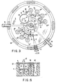
- FIGS. 6 and 7 show details in partial vertical sections made respectively along the line VI-VI and along the line VII-VII of FIG. 3.
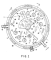
- the example shown refers to a reverse flow carburetor, with seven diffusers arranged in arcs of a circle and cooperating with a rotary shutter, with overflow tank, device for operating at minimum and recovery pump, but, as already said, these choices should not be considered as limiting the scope of the invention.
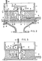
- the structure of the carburetor shown mainly comprises a body 1, a distributor 2 arranged below the body 1, a manifold 4 and a cover 5.
- the latter is applied to the body 1 by means of screws not shown, with the interposition of 'A flat seal 27;
- the distributor 2 is fixed to the body 1 by teeth with elastic trigger 36 and with the interposition of a toroidal sealing gasket 37;
- the manifold 4 is fixed to the distributor 2 by means of teeth with elastic release 38 and with the interposition of a toroidal sealing gasket 39.
- these connection systems assume that the distributor 2 is formed of plastic material , which is made possible by the adoption of the principles of the invention.
- the manifold 4 is intended to be shown on the suction manifold (not shown) of a carburetion engine, and above the cover 5 is intended to be mounted a suction air filter; to fix the latter's box, the cover 5 has threaded rods 25; the air filter is not shown.
- the body 1 is traversed by a plurality of diffusers 6, in this case in number of seven, distributed over a circumference and forming two groups, respectively of four and three diffusers.
- a small tube opens. 12 suitably curved, at the opposite end of which a nozzle is applied 11.
- the various nozzles 11 of the two groups of diffusers sink into respective tanks 35 and 34 which, through conduits 33 and 32, communicate with a central tank at constant level 30.
- This tank is supplied by the usual supply pump (not shown) through a connector 13, a fuel filter 15 and a flow metering nozzle 16.
- the constant level is ensured by a weir 7, and the fuel supplied in excess is poured into an arcuate tank 31, from which it passes to a connector 14 intended to be connected to a recovery pump (not shown), which returns the unused fuel to the tank. Thanks to communications 32 and 33, the same constant level of the tank 30 is also established in the tanks 34 and 35 and submerges, with a preset load, the nozzles 11 of the tubes 12.
- a rotary shutter formed by a disc 3 provided with two arcuate slots 18 and 19. These slots are arranged so that, in a position of the disc 3 (full opening), they leave all free the diffusers 6 of the two groups, in another position (total closure) they close all the diffusers, and, passing from this last position to the first, they first gradually discover the first diffuser 6 '(belonging to the first group) and_then, after having completely opened this first diffuser, they discover the second 6 "diffuser (belonging to the second group), then the third 6"'diffuser (belonging again to the first group) and so on.
- the diffusers 6 are illustrated as all equal, they may have different sections or / and they may be served by nozzles 11 of different caliber, so as to obtain the best dosage for each operating regime .
- the slots 18 and 19 of the shutter 3 ′ may have any other profile in order to obtain a desired law of variation of the total passage section according to the control of the accelerator, this law can be approximately linear, exponential or other, to obtain the best maneuverability of the engine.
- the rotary shutter 3 is controlled by. by means of a shaft 20, which passes through the body 1 and the cover 5 and which, above the latter, is connected to a lever 21 returned to the minimum position by a spring 23 supported on a relief 42 of the cover 5. To the lever 21 will be hooked the bowden or other acceleration control transmission, not shown, acting substantially along the line with dots and lines 43 of FIG. 1.
- a toroidal seal 22 establishes the seal between the small shaft 20 and body 1.
- Operation at minimum regime, in a carburetor according to the invention can be made correct by providing a first diffuser particularly designed for this operation, and in this case no special device should be provided for this purpose.
- a special minimum device such as that shown in Figures 1 and 7 can be adopted.
- one is derived from one of the fuel supply tanks (in the example, the tank 34) a conduit 10 which carries the fuel to an air passage 9 provided for this purpose through the body 1, the distributor 2 and the cover 5.
- the conduit 10 can be more or less throttled by means of a screw needle 26, and the air passage 9 can also be more or less throttled by means of an adjusting screw 17.
- the operation at minimum speed can therefore be conveniently adjusted by means of the screws 17 and 26.
- the passage 9 can be opened permanently, since its cross section is negligible for operation at higher speeds, or it can be conveniently occluded by the rotary shutter 3, from a determined supply speed.
- the recovery pump comprises a piston 28 inserted, without sealing, in a cylinder 8 formed in the body 1, adjacent and in communication, above a wall 44, with the central tank 30 at constant level.
- a conduit 45 which, through a non-return valve 29, opens into the first diffuser 6.
- the piston 28 is pushed upwards by a spring 46 and it is connected to a rod 47 which forms a pusher against a front cam 48 presented below by the lever 21 for controlling the rotary shutter. Therefore, when the shutter is rotated in the direction of increasing the opening of the diffusers, the rod 47 with the piston 28 is lowered. Since the piston does not seal, if the maneuver is slow there is no backflow, but if the maneuver is rapid, fuel is pushed into the duct 45 and is poured into the first diffuser 6, thus providing the supply stronger demanded by rapid acceleration.
- the device for the cold start when requested, can be simply constituted by a flat element 24 pivoted on the shaft 20 and sliding on the cover 5 under the control of a tie rod, not shown, arranged according to the line with dots and lines 50 of FIG. 1.
- the movement of the element 24 is limited, by stops 49 formed by the cover 5, between two positions, in one of which (normal operation) the element 24 does not interfere not with the diffusers 6, while in the other position (cold start) the element 24 partially closes the first diffuser 6.
- the cover 5 is predisposed to receive thereon the body of an air filter. But it is also possible to shape the cover 5 so that it itself forms the seat for the application of a filter cartridge for the aspirated air, thus avoiding providing the carburetor with a special body for the filter and simplifying assembly operations.
- the application of the present invention allows the adoption of forms particularly suitable for manufacturing in molded synthetic material, but when requested the parts of the carburetor according to the invention can be produced with another material, such as zamak (alloy zinc and aluminum) or a light alloy, by die-casting.
- zamak alloy zinc and aluminum
- a light alloy by die-casting.
- the carburetor can be provided with any other kind of constant level tank, for example with float.
- the number of diffusers which in the example is seven, can naturally vary from a minimum of three to a maximum determined by the overall dimensions accepted for the carburetor.
- the angular distance between successive diffusers can be chosen differently, and it can be uniform or even different for the various diffusers.
Landscapes
- Engineering & Computer Science (AREA)
- Chemical & Material Sciences (AREA)
- Combustion & Propulsion (AREA)
- Mechanical Engineering (AREA)
- General Engineering & Computer Science (AREA)
- Control Of The Air-Fuel Ratio Of Carburetors (AREA)
- Means For Warming Up And Starting Carburetors (AREA)
Applications Claiming Priority (2)
| Application Number | Priority Date | Filing Date | Title |
|---|---|---|---|
| IT67919/81A IT1144263B (it) | 1981-07-02 | 1981-07-02 | Carburatore per motori a combustione interna |
| IT6791981 | 1981-07-02 |
Publications (3)
| Publication Number | Publication Date |
|---|---|
| EP0069416A2 EP0069416A2 (fr) | 1983-01-12 |
| EP0069416A3 EP0069416A3 (en) | 1984-03-07 |
| EP0069416B1 true EP0069416B1 (fr) | 1986-10-01 |
Family
ID=11306367
Family Applications (1)
| Application Number | Title | Priority Date | Filing Date |
|---|---|---|---|
| EP82200759A Expired EP0069416B1 (fr) | 1981-07-02 | 1982-06-18 | Carburateur pour moteur à combustion interne |
Country Status (4)
| Country | Link |
|---|---|
| US (1) | US4465641A (it) |
| EP (1) | EP0069416B1 (it) |
| DE (1) | DE3273547D1 (it) |
| IT (1) | IT1144263B (it) |
Families Citing this family (1)
| Publication number | Priority date | Publication date | Assignee | Title |
|---|---|---|---|---|
| IT1224458B (it) * | 1988-09-30 | 1990-10-04 | Marco Morini | Spuzzatore corretto per il carburatore di un motore a carburazione |
Family Cites Families (22)
| Publication number | Priority date | Publication date | Assignee | Title |
|---|---|---|---|---|
| US900604A (en) * | 1904-12-28 | 1908-10-06 | John W Duntley | Carbureter. |
| US948612A (en) * | 1908-04-06 | 1910-02-08 | Krause Carbureter Company | Carbureter for combustion-engines. |
| FR437972A (fr) * | 1911-12-21 | 1912-05-04 | Pierre Velter | Appareil de carburation rationnelle pour moteurs à explosion à gaz, pétrole ou essence |
| US1180976A (en) * | 1915-07-07 | 1916-04-25 | John Leslie Cloudsley | Carbureter. |
| US1205602A (en) * | 1916-01-11 | 1916-11-21 | Thomas John Disturnal | Carbureter. |
| FR488209A (fr) * | 1916-02-23 | 1918-09-14 | Leonard Longley | Perfectionnements apportés aux carburateurs pour moteurs à combustion interne |
| US1485759A (en) * | 1916-12-28 | 1924-03-04 | Ball & Ball Carburetor Company | Carburetor |
| US1586097A (en) * | 1919-05-14 | 1926-05-25 | John J Lyons | Carburtor |
| FR580262A (fr) * | 1924-04-17 | 1924-11-04 | Carburateur | |
| BE340796A (it) * | 1926-04-07 | |||
| FR647181A (fr) * | 1927-06-03 | 1928-11-21 | Carburateur | |
| US1986321A (en) * | 1932-04-23 | 1935-01-01 | Chanard Auguste | Carburetor |
| FR43573E (fr) * | 1933-03-30 | 1934-07-11 | Carburateur | |
| US2049180A (en) * | 1934-03-19 | 1936-07-28 | Surra Stephane | Carburetor for internal combustion engines |
| US2086292A (en) * | 1935-04-02 | 1937-07-06 | Chanard Marthe Louise | Carburetor |
| US2454974A (en) * | 1941-09-23 | 1948-11-30 | Solex | Liquid distributing device |
| FR879212A (fr) * | 1942-02-10 | 1943-02-17 | Carburateur multiple pour moteurs à combustion interne | |
| US2638330A (en) * | 1949-09-13 | 1953-05-12 | Morgenroth Henri | Carburetor |
| US2783981A (en) * | 1953-10-21 | 1957-03-05 | Briggs Res & Dev Inc | Production of combustible mixture of air and fuel vapor |
| US2977099A (en) * | 1959-05-26 | 1961-03-28 | Chrysler Corp | Floatless carburetor |
| FR2260694B1 (it) * | 1974-02-08 | 1976-11-26 | Motobecane Ateliers | |
| US4139580A (en) * | 1977-05-13 | 1979-02-13 | Walbro Corporation | Self-lift carburetor |
-
1981
- 1981-07-02 IT IT67919/81A patent/IT1144263B/it active
-
1982
- 1982-06-18 DE DE8282200759T patent/DE3273547D1/de not_active Expired
- 1982-06-18 EP EP82200759A patent/EP0069416B1/fr not_active Expired
- 1982-06-22 US US06/390,864 patent/US4465641A/en not_active Expired - Fee Related
Also Published As
| Publication number | Publication date |
|---|---|
| IT1144263B (it) | 1986-10-29 |
| EP0069416A3 (en) | 1984-03-07 |
| IT8167919A0 (it) | 1981-07-02 |
| EP0069416A2 (fr) | 1983-01-12 |
| DE3273547D1 (en) | 1986-11-06 |
| US4465641A (en) | 1984-08-14 |
Similar Documents
| Publication | Publication Date | Title |
|---|---|---|
| CH622063A5 (it) | ||
| EP0296969B1 (fr) | Dispositif d'introduction sous pression de mélange carburé dans le cylindre d'un moteur | |
| FR2458446A1 (fr) | Motocyclette | |
| EP0069416B1 (fr) | Carburateur pour moteur à combustion interne | |
| EP0786045B1 (fr) | Moteur deux temps a dispositif d'injection ameliore et procede d'injection associe | |
| EP0346188A1 (fr) | Dispositif et méthode d'introduction sous pression de mélange carburé dans le cylindre d'un moteur | |
| FR2705402A1 (fr) | Boisseau rotatif amélioré. | |
| FR2764944A1 (fr) | Dispositif de carburation permettant de commander le debit et la qualite du melange air/carburant admis dans les moteurs thermiques | |
| FR2776708A1 (fr) | Nouveau moteur a combustion interne a quatre temps, allumage commande et injection directe | |
| FR2667114A1 (fr) | Dispositif d'admission pour moteur a combustion interne. | |
| FR2567194A1 (fr) | Dispositif d'echappement pour moteur a combustion interne a deux temps de balayage. | |
| EP0296899A1 (fr) | Disposition dans une chambre de combustion d'un moteur deux temps, du système d'alimentation en carburant relativement à la lumière d'échappement | |
| FR2803882A1 (fr) | Systeme de moteur hors bord | |
| EP0507648A1 (fr) | Moteur à deux temps à contrôle sélectif de la charge introduite dans la chambre de combustion | |
| FR2575226A1 (fr) | Culasse de moteur a combustion interne | |
| FR2763646A1 (fr) | Moteur a injection directe et allumage commande | |
| FR2487009A1 (fr) | Moteur a combustion interne equipe d'un circuit secondaire d'admission | |
| EP0218515B1 (fr) | Carburateur pour moteur à explosion | |
| FR2511083A1 (fr) | Dispositif d'actionnement de pompe de reprise pour un carburateur | |
| FR2487003A1 (fr) | Moteur a combustion interne a piston rotatif ayant plusieurs lumieres d'admission | |
| FR2761408A1 (fr) | Moteur a deux temps equipe d'un mecanisme simplifie et compact d'activation des soupapes de commande de l'echappement | |
| FR2652388A1 (fr) | Carburateur avec un systeme de ralenti independant. | |
| BE532266A (it) | ||
| BE396856A (it) | ||
| EP0665369B1 (fr) | Procédé et dispositif de commande de l'arrêt d'un moteur deux temps à auto-allumage |
Legal Events
| Date | Code | Title | Description |
|---|---|---|---|
| PUAI | Public reference made under article 153(3) epc to a published international application that has entered the european phase |
Free format text: ORIGINAL CODE: 0009012 |
|
| AK | Designated contracting states |
Designated state(s): DE FR GB SE |
|
| 17P | Request for examination filed |
Effective date: 19830702 |
|
| PUAL | Search report despatched |
Free format text: ORIGINAL CODE: 0009013 |
|
| AK | Designated contracting states |
Designated state(s): DE FR GB SE |
|
| GRAA | (expected) grant |
Free format text: ORIGINAL CODE: 0009210 |
|
| AK | Designated contracting states |
Kind code of ref document: B1 Designated state(s): DE FR GB SE |
|
| PG25 | Lapsed in a contracting state [announced via postgrant information from national office to epo] |
Ref country code: SE Effective date: 19861031 |
|
| REF | Corresponds to: |
Ref document number: 3273547 Country of ref document: DE Date of ref document: 19861106 |
|
| PLBE | No opposition filed within time limit |
Free format text: ORIGINAL CODE: 0009261 |
|
| STAA | Information on the status of an ep patent application or granted ep patent |
Free format text: STATUS: NO OPPOSITION FILED WITHIN TIME LIMIT |
|
| 26N | No opposition filed | ||
| PGFP | Annual fee paid to national office [announced via postgrant information from national office to epo] |
Ref country code: GB Payment date: 19930608 Year of fee payment: 12 |
|
| PGFP | Annual fee paid to national office [announced via postgrant information from national office to epo] |
Ref country code: DE Payment date: 19930623 Year of fee payment: 12 |
|
| PGFP | Annual fee paid to national office [announced via postgrant information from national office to epo] |
Ref country code: FR Payment date: 19930629 Year of fee payment: 12 |
|
| PG25 | Lapsed in a contracting state [announced via postgrant information from national office to epo] |
Ref country code: GB Effective date: 19940618 |
|
| GBPC | Gb: european patent ceased through non-payment of renewal fee |
Effective date: 19940618 |
|
| PG25 | Lapsed in a contracting state [announced via postgrant information from national office to epo] |
Ref country code: FR Effective date: 19950228 |
|
| PG25 | Lapsed in a contracting state [announced via postgrant information from national office to epo] |
Ref country code: DE Effective date: 19950301 |
|
| REG | Reference to a national code |
Ref country code: FR Ref legal event code: ST |