EP0068858A2 - Toner replenishing device for an electrostatic copying apparatus - Google Patents
Toner replenishing device for an electrostatic copying apparatus Download PDFInfo
- Publication number
- EP0068858A2 EP0068858A2 EP82303352A EP82303352A EP0068858A2 EP 0068858 A2 EP0068858 A2 EP 0068858A2 EP 82303352 A EP82303352 A EP 82303352A EP 82303352 A EP82303352 A EP 82303352A EP 0068858 A2 EP0068858 A2 EP 0068858A2
- Authority
- EP
- European Patent Office
- Prior art keywords
- storing box
- toner
- replenishing device
- wheels
- toner replenishing
- Prior art date
- Legal status (The legal status is an assumption and is not a legal conclusion. Google has not performed a legal analysis and makes no representation as to the accuracy of the status listed.)
- Granted
Links
- 238000003756 stirring Methods 0.000 claims abstract description 24
- 239000000463 material Substances 0.000 description 21
- 108091008695 photoreceptors Proteins 0.000 description 11
- 230000002093 peripheral effect Effects 0.000 description 9
- 230000009977 dual effect Effects 0.000 description 5
- 238000000034 method Methods 0.000 description 3
- 238000004140 cleaning Methods 0.000 description 2
- 238000004804 winding Methods 0.000 description 2
- 238000001514 detection method Methods 0.000 description 1
- 230000008030 elimination Effects 0.000 description 1
- 238000003379 elimination reaction Methods 0.000 description 1
- 239000000696 magnetic material Substances 0.000 description 1
- 239000002245 particle Substances 0.000 description 1
- 238000000926 separation method Methods 0.000 description 1
Images


Classifications
-
- G—PHYSICS
- G03—PHOTOGRAPHY; CINEMATOGRAPHY; ANALOGOUS TECHNIQUES USING WAVES OTHER THAN OPTICAL WAVES; ELECTROGRAPHY; HOLOGRAPHY
- G03G—ELECTROGRAPHY; ELECTROPHOTOGRAPHY; MAGNETOGRAPHY
- G03G15/00—Apparatus for electrographic processes using a charge pattern
- G03G15/06—Apparatus for electrographic processes using a charge pattern for developing
- G03G15/08—Apparatus for electrographic processes using a charge pattern for developing using a solid developer, e.g. powder developer
- G03G15/0822—Arrangements for preparing, mixing, supplying or dispensing developer
- G03G15/0865—Arrangements for supplying new developer
- G03G15/0875—Arrangements for supplying new developer cartridges having a box like shape
-
- G—PHYSICS
- G03—PHOTOGRAPHY; CINEMATOGRAPHY; ANALOGOUS TECHNIQUES USING WAVES OTHER THAN OPTICAL WAVES; ELECTROGRAPHY; HOLOGRAPHY
- G03G—ELECTROGRAPHY; ELECTROPHOTOGRAPHY; MAGNETOGRAPHY
- G03G15/00—Apparatus for electrographic processes using a charge pattern
- G03G15/06—Apparatus for electrographic processes using a charge pattern for developing
- G03G15/08—Apparatus for electrographic processes using a charge pattern for developing using a solid developer, e.g. powder developer
- G03G15/0822—Arrangements for preparing, mixing, supplying or dispensing developer
- G03G15/0877—Arrangements for metering and dispensing developer from a developer cartridge into the development unit
-
- Y—GENERAL TAGGING OF NEW TECHNOLOGICAL DEVELOPMENTS; GENERAL TAGGING OF CROSS-SECTIONAL TECHNOLOGIES SPANNING OVER SEVERAL SECTIONS OF THE IPC; TECHNICAL SUBJECTS COVERED BY FORMER USPC CROSS-REFERENCE ART COLLECTIONS [XRACs] AND DIGESTS
- Y10—TECHNICAL SUBJECTS COVERED BY FORMER USPC
- Y10S—TECHNICAL SUBJECTS COVERED BY FORMER USPC CROSS-REFERENCE ART COLLECTIONS [XRACs] AND DIGESTS
- Y10S222/00—Dispensing
- Y10S222/01—Xerography
Definitions
- the present invention relates to a toner replenishing device for replenishing toner to a developing device in an electrostatic copying apparatus.
- a primary object of the present invention is to provide a toner replenishing device which is arranged to be capable of stably replenishing the toner through substantial elimination of drawbacks in the conventional arrangements of this kind.
- a toner replenishing device which comprises a supply roller with respect to a supply port at an end of a storing box extending in an approximate horizontal direction, a pair of winding wheels at a position adjacent to the supply roller and at the other end of the storing box, a stirring and supply rod provided between a pair of endless stretched members passed around the wheels close to opposite side walls of the storing box. The lower portions of the endless stretched members are driven toward the supply roller.
- the toner is gathered in the vicinity of the peripheral surface of the supply roller until the toner is almost completely used up,stable supply of the toner may be achieved.
- the wheels are sprockets or pulleys and the endless stretched members are chains, wires or belts.
- the width of the storing box may be selected corresponding to the entire length of a developing roller, the supply port may be formed between the opposite side walls of the storing box.
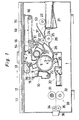
- FIG. 1 a schematic vertical sectional view of a transfer type electrostatic copying apparatus, .as viewed from the front side, according to a preferred embodiment of the present invention.
- a photosensitive or photoreceptor drum 4 prepared by applying a photosensitive layer 3 onto an outer peripheral surface of a drum 2.
- a corona charger 6 for uniformly charging the photosensitive layer 3
- a developing device 7 for developing an electrostatic latent image formed on the photosensitive layer 3 into a visible toner image
- a transfer corona charger 8 for transferring the-toner image on the photosensitive layer 3 onto a copy paper sheet
- a separation corona charger 9 for separating the copy paper sheet from the photosensitive layer 3
- a cleaning device 10 for cleaning the toner remaining on the photosensitive layer 3 after the transfer process.
- an original document support table 12 for reciprocation in the directions as indicated by arrows, with an original document 11 horizontally placed thereon.
- the original document 11 on said support table 12 is held in position by an original document presser member 13 provided on said support table 12.
- an exposure device 14 is provided for projecting light image of the original document 11 onto the photosensitive layer 3 in a position between the corona charger 6 and the developing device 7 as indicated by dotted line arrows.
- a light projection means 15 for projecting light onto the original document 11 through the original document support table 12 further includes an exposure lamp 16, a reflection plate 17 and an auxiliary reflecting plate 18.
- the light directed from the above light projection means 15 onto the original document 11 on the original document support table 12 is projected onto the photosensitive layer 3 through a single focal point lens 19 to form the image of the original document 11 in the form of the electrostatic latent image on said photosensitive layer 3.
- copy paper sheets accommodated in a stack, on a copy paper feeding cassette 21 provided at a lower right hand side of the apparatus housing 1 in Fig. 1 are fed therefrom, one sheet by one sheet, by a copy paper feeding roller 22 through a copy paper transport path 20 represented by a two dotted chain line.
- the copy paper sheet is transported by a set of feed-in transport rollers 25 and 26 through a set of an upper and a lower guide plates 23 and 24.
- the copy paper sheet fed into a transfer region 29 through a set of an upper and a lower guide plates 27 and 28 is further transported in a state where it is closely adhering to the photoreceptor drum 4 confronting the transfer corona charger 8.
- the copy paper sheet is separated from the photoreceptor drum 4 by the separating corona charger 9, and is fed into a heat fixing device 33 equipped with a pair of heat fixing rollers 31 and 32 by a copy paper transport device 30.
- a heat fixing device 33 equipped with a pair of heat fixing rollers 31 and 32 by a copy paper transport device 30.
- the toner image on the copy paper sheet is fixed onto said copy paper sheet through thermal fusing.
- the copy paper sheet is discharged onto a copy. paper tray 36 provided at the left in Fig. 1 through a set of discharge rollers 34 and 35.
- a dual component developing material including toner and carrier particles is stored.
- the toner is consumed according to the developing processing, and fresh toner is replenished from the toner replenishing device 37 according to the amount of the toner consumption mentioned above.
- said developing device 7 includes a developing roller 38 disposed in a parallel relation with respect to an axis of the photoreceptor drum 4 and in a position close to the photosensitive layer 3 of said photoreceptor drum 4, a storage container 39 for storing therein the dual component developing material, a stirring or agitating means 40 for stirring said developing material within said storage container 39, a stirring and supplying means 41 for stirring the developing material within said storage container 39 and also for supplying said developing material towards the developing roller 38, and a doctor blade 42 for restricting the length of brush bristles of magnetic brush to be formed on the outer peripheral surface of the developing roller 38.
- a scraping-off plate 43 Within the storage container 39, at a opposite position toward the photoreceptor drum 4 with respect to the developing roller 38, there is provided a scraping-off plate 43, and between said scraping-off plate 43 and the inner wall of the storage container 39, a developing material storing portion 44 is formed. At the upper part of the developing material storing portion 44 within said storage container 39, an opening 45 is formed as shown.
- the stirring means 40 referred to above is provided at the upper portion of the developing material storing portion 44 in a relation parallel to the developing roller 38, while the stirring and supplying means 41 is disposed at the lower portion of the developing material storing portion 44 in a relation parallel to the stirring means 40. As shown in Fig.
- the stirring means 40 comprises a rotary rod 46 having its axis directed in parallel to that of the developing roller 38, a plurality of discs 47 fixed to said rotary rod 46 in a spaced relation to each other along the axial direction of the rotary rod 46, and directed slantwise with respect to the axis of said rod 46, and corresponding number of flat plates 48 respectively extending radially and outwardly in opposite directions on one diametrical line of the rotary rod 46, between the respective discs 47 as shown.
- The.stirring and supplying means 41 is constructed generally in the similar manner to that of the stirring means 40 as described above. These stirring means 40, and stirring and supplying means 41 are driven for rotation about the axes thereof by a driving force from a driving source not particularly shown.
- the developing roller 38 comprises a hollow developing sleeve 49 of a non-magnetic material, and a permanent magnet 50 concentrically fixed within said developing sleeve 49, which is driven for rotation in a direction indicated by a solid line arrow.
- the developing material supplied onto the outer peripheral surface of the developing roller 38 from the developing material storing portion 44 by the stirring and supplying means 41 is restricted for the bristle length by the doctor blade 42 so as to form the magnetic brush, which rubs against the peripheral surface of the photosensitive layer 3 for developing the electrostatic latent image formed on said photosensitive layer 3.
- a level detector 51 for driving a motor 66 with the toner replenishing device 37 (see Fig. 4 to be described later), through detection of lowering of the upper level for the develo p ina material in the developing material storing portion 44 according to the consumption of the toner.
- a detector which is adapted to detect the level through utilization, for example, of mutual inductance may be employed.
- the toner replenishing device 37 includes a storing box 53 extending in a direction at right angles with respect to the axis of the developing roller 38, for example, in a horizontal direction so as to be opened at the upper portion as illustrated, and having a.supply port 52 in a bottom portion 53a at an end along said horizontal direction (see Fig.
- a supply roller 54 provided in a position close to the supply port 52 within said storing box 53
- a pair of sprockets 55 and another pair of sprockets 56 respectively rotatably mounted on opposite side walls 53b and 53c of the storing box 53 in a position close to said supply roller 54 and another position adjacent to the other end of said storing box 53 so as to serve as winding wheels
- a pair of chains 57 and 58 respectively passed around the corresponding sprockets 55 and 56 serving as endless stretched members
- a stirring and supply rod 59 provided on the chains 57 and 58 so as to extend between the same positions along the longitudinal direction of the storing box 53, namely, along the direction at right angles with respect to the axis of the developing roller 38.
- the upper portion of the storing box 53 may be arranged to be closed by a cover member 70 which can be selectively raised for opening or lowered for closing, and that the length in the widthwise direction at right angles with respect to the longitudinal direction of the storing box 53 should preferably be selected corresponding to the entire length in the axial direction of the photoreceptor drum 4, and also, the supply port 52 should preferably be formed over the entire length in the axial direction of the photoreceptor drum 4.
- An end portion of the storing box 53 is located above the developing material storing portion 44 within the storage container 39 of the developing device 7 as is seen in Fig. 2. Moreover, the bottom portion 53a at an end of the storing box 53 is curved so as to be convex downwardly for being projected into the storage container 39 from the opening portion 45.
- the supply roller 54 is rotatably provided to extend between the opposite side walls 53b and 53c.
- the above supply roller 54 is, for example, a sponge-like roller which is arranged to be in sliding contact with peripheral edges of the supply port 52.
- ladder chains and the like may be selected.
- an end of a coil spring 60 is connected, while the other end of said coil spring 60 is engaged with the chain 57 or 58 for supporting the stirring and supply rod 59.
- the sets of the sprockets 55 and 56 are respectively provided in positions close to the inner faces of the opposite side walls 53b and 53c, and therefore, the stirring and supply rod 59 and coil spring 60 connected thereto are provided to generally extend between the opposite side walls 53b and 53c.
- FIG. 5 schematically showing the side elevational view of the toner replenishing device 37.
- a rotary shaft 61 for one of the pair of sprockets 55 is rotatably extended through the side wall 53b, while a gear 62 is fixedly mounted on the outer end of said shaft 61.
- a rotary shaft 63 of the supply roller 54 rotatably extends, at its opposite ends, through the side walls 53b and 53c, with a gear 64 being secured to an end of the shaft 63 as shown.
- the gear 64 is engaged with the gear 62 described earlier, through a gear 65 rotatably mounted on the side wall 53b.
- the motor 66 In an outer position corresponding to the side wall 53c of the storing box 53, there is provided the motor 66, while the output shaft 67 of the motor 66 is connected to the other end of the rotary shaft 63 referred to previously.
- the motor 66 is arranged to be driven when the level of the developing material in the developing material storing portion 44 is detected to be reduced lower than the predetermined level by the level detector 51. By the driving force of this motor 66, the supply roller 54 is driven for rotation in the direction of an arrow 69, while the chains 57 and 58 are caused to run in the direction of an arrow 68 through the gears 64, 65 and 62.
- the chains 57 and 58 are driven to move by the driving force of the motor 66, and according to the running of said chains 57 and 58, the stirring and supply rod 59 is moved in the direction indicated by the arrow 68. Therefore, the toner stored in the storing box 53 is moved towards the supply roller 54 by the stirring and supply rod 59 in a portion close to the bottom portion 53d of the storing box 53. Meanwhile, at the upper part in the storing box 53, the toner is moved in a direction to be spaced from the supply roller 54 by the stirring and supply rod 59. Consequently, toner is sufficiently agitated within the storing box 53, with the peripheral surface of the supply roller 54 being in contact with the toner at all times.
- the sprockets 55 and 56, and also, the chains 57 and 58 described as employed in the foregoing embodiment may be replaced, for example, by pulleys, and wires or belts, and that, although the present invention has been described with reference to the dual component developing material in the embodiment described so far, the replenishing device of the present invention is not limited, in its application, to the dual component developing material alone, but may readily be used as a replenishing device for replenishing a mono- component developing material as well.
Abstract
Description
- The present invention relates to a toner replenishing device for replenishing toner to a developing device in an electrostatic copying apparatus.
- There has been well known an arrangement for supplying a proper amount of toner to a developing device through rotation of a sponge-like roller for a proper period of time. However, in order to realize the arrangement as described above, it is required to maintain the state in which the toner is contacting the peripheral surface of the sponge-like roller at all times, while it is also necessary to replenish a large amount of toner for effecting copying of a large number of copy paper sheets. Therefore, it has been consequently required that the toner in a comparatively great bulk should be stored in an accommodating or storing box. Accordingly, no toner replenishing device employing a storing box with a shallow bottom has been put into practical application up to the present, and even by a storing box having a deep bottom, it has been impossible to stably supply the toner to the developing device before the toner is almost completely consumed.
- Therefore, a primary object of the present invention is to provide a toner replenishing device which is arranged to be capable of stably replenishing the toner through substantial elimination of drawbacks in the conventional arrangements of this kind.
- To accomplish the foregoing object, there is provided a toner replenishing device which comprises a supply roller with respect to a supply port at an end of a storing box extending in an approximate horizontal direction, a pair of winding wheels at a position adjacent to the supply roller and at the other end of the storing box, a stirring and supply rod provided between a pair of endless stretched members passed around the wheels close to opposite side walls of the storing box. The lower portions of the endless stretched members are driven toward the supply roller.
- According to this invention, since the toner is gathered in the vicinity of the peripheral surface of the supply roller until the toner is almost completely used up,stable supply of the toner may be achieved.
- In accordance with the preferred embodiment, the wheels are sprockets or pulleys and the endless stretched members are chains, wires or belts. The width of the storing box may be selected corresponding to the entire length of a developing roller, the supply port may be formed between the opposite side walls of the storing box.
- This invention will now be illustrated in more detail by reference to embodiment in accompanying drawings.
- Fig. 1 is a schematic vertical sectional view of a transfer type electrostatic copying apparatus as observed from the front side according to a preferred embodiment;
- Fig. 2 is a sectional view in the vicinity of a developing device and a toner replenishing device;
- Fig. 3 is a partial perspective view of a stirring means;
- Fig. 4 is a top plan view of the toner replenishing device; and
- Fig. 5 is a schematic side elevational view of the toner replenishing device.
- Referring now to the drawings, there is shown in Fig. 1 a schematic vertical sectional view of a transfer type electrostatic copying apparatus, .as viewed from the front side, according to a preferred embodiment of the present invention. At approximately a central portion of an apparatus housing l,there is rotatably provided a photosensitive or
photoreceptor drum 4 prepared by applying aphotosensitive layer 3 onto an outer peripheral surface of adrum 2. Around thephotoreceptor drum 4, there are sequentially disposed, along a direction of rotation of saiddrum 4 indicated by anarrow 5, various processing devices such as acorona charger 6 for uniformly charging thephotosensitive layer 3, a developingdevice 7 for developing an electrostatic latent image formed on thephotosensitive layer 3 into a visible toner image, atransfer corona charger 8 for transferring the-toner image on thephotosensitive layer 3 onto a copy paper sheet, aseparation corona charger 9 for separating the copy paper sheet from thephotosensitive layer 3, and acleaning device 10 for cleaning the toner remaining on thephotosensitive layer 3 after the transfer process. - Meanwhile, at an upper portion of the apparatus housing 1, there is movably disposed an original document support table 12 for reciprocation in the directions as indicated by arrows, with an original document 11 horizontally placed thereon. The original document 11 on said support table 12 is held in position by an original
document presser member 13 provided on said support table 12. Above thephotoreceptor drum 4, an exposure device 14 is provided for projecting light image of the original document 11 onto thephotosensitive layer 3 in a position between thecorona charger 6 and the developingdevice 7 as indicated by dotted line arrows. In the exposure device 14, a light projection means 15 for projecting light onto the original document 11 through the original document support table 12 further includes anexposure lamp 16, areflection plate 17 and anauxiliary reflecting plate 18. The light directed from the above light projection means 15 onto the original document 11 on the original document support table 12 is projected onto thephotosensitive layer 3 through a singlefocal point lens 19 to form the image of the original document 11 in the form of the electrostatic latent image on saidphotosensitive layer 3. - On the other hand, copy paper sheets accommodated in a stack, on a copy
paper feeding cassette 21 provided at a lower right hand side of the apparatus housing 1 in Fig. 1 are fed therefrom, one sheet by one sheet, by a copypaper feeding roller 22 through a copypaper transport path 20 represented by a two dotted chain line. The copy paper sheet is transported by a set of feed-intransport rollers lower guide plates transfer region 29 through a set of an upper and alower guide plates photoreceptor drum 4 confronting thetransfer corona charger 8. After the transfer process, the copy paper sheet is separated from thephotoreceptor drum 4 by the separatingcorona charger 9, and is fed into aheat fixing device 33 equipped with a pair ofheat fixing rollers paper transport device 30. In theheat fixing device 33 as described above, the toner image on the copy paper sheet is fixed onto said copy paper sheet through thermal fusing. After the fixing process, the copy paper sheet is discharged onto a copy.paper tray 36 provided at the left in Fig. 1 through a set ofdischarge rollers - In the developing
device 7, a dual component developing material including toner and carrier particles is stored. In the dual component developing material as described above, the toner is consumed according to the developing processing, and fresh toner is replenished from the toner replenishingdevice 37 according to the amount of the toner consumption mentioned above. - Referring particularly to Fig. 2 showing a cross sectional view in the vicinity of the developing
device 7 and the toner replenishingdevice 37 on an enlarged scale, said developingdevice 7 includes a developingroller 38 disposed in a parallel relation with respect to an axis of thephotoreceptor drum 4 and in a position close to thephotosensitive layer 3 of saidphotoreceptor drum 4, astorage container 39 for storing therein the dual component developing material, a stirring or agitatingmeans 40 for stirring said developing material within saidstorage container 39, a stirring andsupplying means 41 for stirring the developing material within saidstorage container 39 and also for supplying said developing material towards the developingroller 38, and adoctor blade 42 for restricting the length of brush bristles of magnetic brush to be formed on the outer peripheral surface of the developingroller 38. Within thestorage container 39, at a opposite position toward thephotoreceptor drum 4 with respect to the developingroller 38, there is provided a scraping-offplate 43, and between said scraping-offplate 43 and the inner wall of thestorage container 39, a developingmaterial storing portion 44 is formed. At the upper part of the developingmaterial storing portion 44 within saidstorage container 39, anopening 45 is formed as shown. - The stirring means 40 referred to above is provided at the upper portion of the developing
material storing portion 44 in a relation parallel to the developingroller 38, while the stirring andsupplying means 41 is disposed at the lower portion of the developingmaterial storing portion 44 in a relation parallel to thestirring means 40. As shown in Fig. 3, the stirring means 40 comprises arotary rod 46 having its axis directed in parallel to that of the developingroller 38, a plurality ofdiscs 47 fixed to saidrotary rod 46 in a spaced relation to each other along the axial direction of therotary rod 46, and directed slantwise with respect to the axis of saidrod 46, and corresponding number offlat plates 48 respectively extending radially and outwardly in opposite directions on one diametrical line of therotary rod 46, between therespective discs 47 as shown. The.stirring and supplyingmeans 41 is constructed generally in the similar manner to that of the stirring means 40 as described above. These stirring means 40, and stirring and supplyingmeans 41 are driven for rotation about the axes thereof by a driving force from a driving source not particularly shown. - The developing
roller 38 comprises a hollow developingsleeve 49 of a non-magnetic material, and apermanent magnet 50 concentrically fixed within said developingsleeve 49, which is driven for rotation in a direction indicated by a solid line arrow. The developing material supplied onto the outer peripheral surface of the developingroller 38 from the developingmaterial storing portion 44 by the stirring andsupplying means 41 is restricted for the bristle length by thedoctor blade 42 so as to form the magnetic brush, which rubs against the peripheral surface of thephotosensitive layer 3 for developing the electrostatic latent image formed on saidphotosensitive layer 3. - To a side wall of the
storage container 39 corresponding to the upper portion of the developingmaterial storing portion 44, there is secured alevel detector 51 for driving amotor 66 with the toner replenishing device 37 (see Fig. 4 to be described later), through detection of lowering of the upper level for the developina material in the developingmaterial storing portion 44 according to the consumption of the toner. For thelevel detector 51, a detector which is adapted to detect the level through utilization, for example, of mutual inductance may be employed. - Referring further to Fig. 4, there is shown a top plan view of the toner replenishing
device 37. The toner replenishingdevice 37 referred to above includes astoring box 53 extending in a direction at right angles with respect to the axis of the developingroller 38, for example, in a horizontal direction so as to be opened at the upper portion as illustrated, and having a.supply port 52 in abottom portion 53a at an end along said horizontal direction (see Fig. 2 also), asupply roller 54 provided in a position close to thesupply port 52 within saidstoring box 53, a pair ofsprockets 55 and another pair ofsprockets 56 respectively rotatably mounted onopposite side walls storing box 53 in a position close to saidsupply roller 54 and another position adjacent to the other end of said storingbox 53 so as to serve as winding wheels, a pair ofchains corresponding sprockets supply rod 59 provided on thechains storing box 53, namely, along the direction at right angles with respect to the axis of the developingroller 38. - It should be noted here that the upper portion of the
storing box 53 may be arranged to be closed by acover member 70 which can be selectively raised for opening or lowered for closing, and that the length in the widthwise direction at right angles with respect to the longitudinal direction of thestoring box 53 should preferably be selected corresponding to the entire length in the axial direction of thephotoreceptor drum 4, and also, thesupply port 52 should preferably be formed over the entire length in the axial direction of thephotoreceptor drum 4. By the above arrangement, since the toner is uniformly supplied into the developingdevice 7 over approximately the entire length of thephotoreceptor drum 4, undesirable supplying of the toner to a particular position within the developingdevice 7 can be prevented. - An end portion of the
storing box 53 is located above the developingmaterial storing portion 44 within thestorage container 39 of the developingdevice 7 as is seen in Fig. 2. Moreover, thebottom portion 53a at an end of thestoring box 53 is curved so as to be convex downwardly for being projected into thestorage container 39 from theopening portion 45. In a position corresponding to thesupply port 52 of thestoring box 53, thesupply roller 54 is rotatably provided to extend between theopposite side walls above supply roller 54 is, for example, a sponge-like roller which is arranged to be in sliding contact with peripheral edges of thesupply port 52. - For the pair of
chains supply rod 59, an end of acoil spring 60 is connected, while the other end of saidcoil spring 60 is engaged with thechain supply rod 59. It is to be noted here that the sets of thesprockets opposite side walls supply rod 59 andcoil spring 60 connected thereto are provided to generally extend between theopposite side walls - Reference is further made to Fig. 5 schematically showing the side elevational view of the toner replenishing
device 37. Arotary shaft 61 for one of the pair ofsprockets 55 is rotatably extended through theside wall 53b, while agear 62 is fixedly mounted on the outer end of saidshaft 61. Arotary shaft 63 of thesupply roller 54 rotatably extends, at its opposite ends, through theside walls gear 64 being secured to an end of theshaft 63 as shown. Thegear 64 is engaged with thegear 62 described earlier, through agear 65 rotatably mounted on theside wall 53b. In an outer position corresponding to theside wall 53c of thestoring box 53, there is provided themotor 66, while theoutput shaft 67 of themotor 66 is connected to the other end of therotary shaft 63 referred to previously. - The
motor 66 is arranged to be driven when the level of the developing material in the developingmaterial storing portion 44 is detected to be reduced lower than the predetermined level by thelevel detector 51. By the driving force of thismotor 66, thesupply roller 54 is driven for rotation in the direction of anarrow 69, while thechains arrow 68 through thegears - In the toner replenishing
device 37 as described above, thechains motor 66, and according to the running of saidchains supply rod 59 is moved in the direction indicated by thearrow 68. Therefore, the toner stored in thestoring box 53 is moved towards thesupply roller 54 by the stirring andsupply rod 59 in a portion close to thebottom portion 53d of thestoring box 53. Meanwhile, at the upper part in thestoring box 53, the toner is moved in a direction to be spaced from thesupply roller 54 by the stirring andsupply rod 59. Consequently, toner is sufficiently agitated within thestoring box 53, with the peripheral surface of thesupply roller 54 being in contact with the toner at all times. - Accordingly, even when a depth h (Fig. 2) of the
storing box 53 is small, the toner within thestoring box 53 is fully stirred, while, since the toner is always staying in the vicinity of the peripheral surface of thesupply roller 54, stable supply of the toner may be achieved until it is almost completely used up. - It should be noted here that, for another embodiment of the present invention, the
sprockets chains - The invention may be embodied in other specific forms without departing from the spirit or essential characteristics thereof. The present embodiments are therefore to be considered in all respects as illustrative and not restrictive, the scope of the invention being indicated by the appended claims rather than by the foregoing description and all changes which come within the meaning and range of equivalency of the claims are therefore intended to be embraced therein.
Claims (4)
Applications Claiming Priority (2)
| Application Number | Priority Date | Filing Date | Title |
|---|---|---|---|
| JP56102944A JPS584162A (en) | 1981-06-30 | 1981-06-30 | Toner feeder |
| JP102944/81 | 1981-06-30 |
Publications (3)
| Publication Number | Publication Date |
|---|---|
| EP0068858A2 true EP0068858A2 (en) | 1983-01-05 |
| EP0068858A3 EP0068858A3 (en) | 1983-08-03 |
| EP0068858B1 EP0068858B1 (en) | 1985-11-06 |
Family
ID=14340933
Family Applications (1)
| Application Number | Title | Priority Date | Filing Date |
|---|---|---|---|
| EP82303352A Expired EP0068858B1 (en) | 1981-06-30 | 1982-06-25 | Toner replenishing device for an electrostatic copying apparatus |
Country Status (4)
| Country | Link |
|---|---|
| US (1) | US4477173A (en) |
| EP (1) | EP0068858B1 (en) |
| JP (1) | JPS584162A (en) |
| DE (1) | DE3267271D1 (en) |
Cited By (4)
| Publication number | Priority date | Publication date | Assignee | Title |
|---|---|---|---|---|
| GB2231171A (en) * | 1989-04-19 | 1990-11-07 | Ricoh Kk | Toner supply device for electrophotographic equipment |
| EP0505214A2 (en) * | 1991-03-22 | 1992-09-23 | Lexmark International, Inc. | Toner metering apparatus with pressure equalization |
| US5878309A (en) * | 1994-10-17 | 1999-03-02 | Canon Kabushiki Kaisha | Toner container, toner container assembling method, process cartridge, and electrophotographic image forming apparatus |
| US6702423B2 (en) | 1998-05-27 | 2004-03-09 | Canon Kabushiki Kaisha | Cleaning device for inkjet printing head, cleaning method for inkjet printing head, inkjet recording apparatus, and wiper |
Families Citing this family (10)
| Publication number | Priority date | Publication date | Assignee | Title |
|---|---|---|---|---|
| US4906104A (en) * | 1987-03-03 | 1990-03-06 | Minolta Camera Kabushiki Kaisha | Agitating and supplying device and a mold for molding same |
| JPS6432275A (en) * | 1987-07-28 | 1989-02-02 | Minolta Camera Kk | Driving method for image forming device |
| JP2517135B2 (en) * | 1990-01-22 | 1996-07-24 | 松下電器産業株式会社 | Electrophotographic equipment |
| US5264900A (en) * | 1991-06-14 | 1993-11-23 | Oki Electric Industry Co., Ltd. | Developing device including toner hopper and toner cartridge stirring portions |
| JPH06210589A (en) * | 1993-01-14 | 1994-08-02 | Itami Kogyo Kk | Cutting device for sheet material |
| US5619312A (en) * | 1993-11-10 | 1997-04-08 | Sharp Kabushiki Kaisha | Developing device with developer-supplying mechanism |
| US5828934A (en) * | 1995-06-07 | 1998-10-27 | Konica Corporation | Driving device of developing units and toner replenishing units for use in image forming apparatus |
| US5860048A (en) * | 1997-07-03 | 1999-01-12 | Oki America, Inc. | Toner stirrer for toner cartridge of developer hopper |
| US6671481B1 (en) * | 2002-10-29 | 2003-12-30 | Hewlett-Packard Development Company, L.P. | Endless belt dry toner agitator |
| JP6012214B2 (en) * | 2011-04-20 | 2016-10-25 | キヤノン株式会社 | Development device |
Citations (5)
| Publication number | Priority date | Publication date | Assignee | Title |
|---|---|---|---|---|
| DE2507618A1 (en) * | 1974-02-22 | 1975-08-28 | Canon Kk | DRY DEVELOPER |
| US3908596A (en) * | 1974-04-29 | 1975-09-30 | Xerox Corp | Segmented gate developer flow controller |
| DE2525952A1 (en) * | 1974-07-17 | 1976-02-05 | Savin Business Machines Corp | MONITORING SYSTEM FOR TONER CONCENTRATION, IN PARTICULAR FOR DRY COPY MACHINES |
| DE2262773B2 (en) * | 1971-12-27 | 1979-01-18 | K.K. Ricoh, Tokio | Toner supply device |
| DE2847768A1 (en) * | 1977-11-05 | 1979-05-10 | Minolta Camera Kk | ELECTROGRAPHIC DEVELOPMENT PROCESS |
Family Cites Families (5)
| Publication number | Priority date | Publication date | Assignee | Title |
|---|---|---|---|---|
| US3610474A (en) * | 1969-10-06 | 1971-10-05 | Shunk Mfg Co Inc | Material conveyor and spreader |
| JPS5848901B2 (en) * | 1974-06-28 | 1983-10-31 | 株式会社リコー | Fukushiya Souchino Toner Kiyoukiyuusouchi |
| JPS5279940A (en) * | 1975-12-26 | 1977-07-05 | Fuji Xerox Co Ltd | Toner replenisher |
| JPS5476240A (en) * | 1977-11-30 | 1979-06-18 | Ricoh Co Ltd | Toner feeder |
| JPS5952832B2 (en) * | 1978-06-26 | 1984-12-21 | 富士ゼロックス株式会社 | Toner supply device |
-
1981
- 1981-06-30 JP JP56102944A patent/JPS584162A/en active Granted
-
1982
- 1982-06-25 EP EP82303352A patent/EP0068858B1/en not_active Expired
- 1982-06-25 DE DE8282303352T patent/DE3267271D1/en not_active Expired
- 1982-06-30 US US06/393,871 patent/US4477173A/en not_active Expired - Fee Related
Patent Citations (5)
| Publication number | Priority date | Publication date | Assignee | Title |
|---|---|---|---|---|
| DE2262773B2 (en) * | 1971-12-27 | 1979-01-18 | K.K. Ricoh, Tokio | Toner supply device |
| DE2507618A1 (en) * | 1974-02-22 | 1975-08-28 | Canon Kk | DRY DEVELOPER |
| US3908596A (en) * | 1974-04-29 | 1975-09-30 | Xerox Corp | Segmented gate developer flow controller |
| DE2525952A1 (en) * | 1974-07-17 | 1976-02-05 | Savin Business Machines Corp | MONITORING SYSTEM FOR TONER CONCENTRATION, IN PARTICULAR FOR DRY COPY MACHINES |
| DE2847768A1 (en) * | 1977-11-05 | 1979-05-10 | Minolta Camera Kk | ELECTROGRAPHIC DEVELOPMENT PROCESS |
Cited By (7)
| Publication number | Priority date | Publication date | Assignee | Title |
|---|---|---|---|---|
| GB2231171A (en) * | 1989-04-19 | 1990-11-07 | Ricoh Kk | Toner supply device for electrophotographic equipment |
| GB2231171B (en) * | 1989-04-19 | 1993-04-14 | Ricoh Kk | Toner supply device for electrophotographic equipment |
| EP0505214A2 (en) * | 1991-03-22 | 1992-09-23 | Lexmark International, Inc. | Toner metering apparatus with pressure equalization |
| EP0505214A3 (en) * | 1991-03-22 | 1993-04-14 | Lexmark International, Inc. | Toner metering apparatus with pressure equalization |
| US5878309A (en) * | 1994-10-17 | 1999-03-02 | Canon Kabushiki Kaisha | Toner container, toner container assembling method, process cartridge, and electrophotographic image forming apparatus |
| US6215969B1 (en) | 1994-10-17 | 2001-04-10 | Canon Kabushiki Kaisha | Toner container, toner container assembling method, process cartridge, and electrophotographic image forming apparatus |
| US6702423B2 (en) | 1998-05-27 | 2004-03-09 | Canon Kabushiki Kaisha | Cleaning device for inkjet printing head, cleaning method for inkjet printing head, inkjet recording apparatus, and wiper |
Also Published As
| Publication number | Publication date |
|---|---|
| JPS584162A (en) | 1983-01-11 |
| US4477173A (en) | 1984-10-16 |
| DE3267271D1 (en) | 1985-12-12 |
| EP0068858B1 (en) | 1985-11-06 |
| JPS6367183B2 (en) | 1988-12-23 |
| EP0068858A3 (en) | 1983-08-03 |
Similar Documents
| Publication | Publication Date | Title |
|---|---|---|
| US9829848B2 (en) | Image forming apparatus | |
| US5592267A (en) | Image forming apparatus using fresh toner and used toner | |
| EP0068858B1 (en) | Toner replenishing device for an electrostatic copying apparatus | |
| US5121168A (en) | Image forming apparatus having a used toner storage portion | |
| US4657369A (en) | Disposable photoconductive belt assembly for a printer or a copier | |
| JPH0274973A (en) | Electrophotographic type copier with improved type developing device | |
| KR0161967B1 (en) | Developing unit of phase fixing device | |
| US5223898A (en) | Developing apparatus with the following roller closer to the drum than the first roller | |
| US4416531A (en) | Electrophotographic copying apparatus and subsystems therefor | |
| US4400078A (en) | Electrophotographic copying apparatus and subsystems therefor | |
| US4506972A (en) | Developing device with means to prevent scattering | |
| JPS61264366A (en) | Developing device | |
| US4384784A (en) | Electrophotographic copying apparatus and subsystems therefor | |
| JPS61264367A (en) | Developing device | |
| JP2001051496A (en) | Developing device and color image forming device | |
| JPS6232470B2 (en) | ||
| JP3577688B2 (en) | Image forming device | |
| JP2505713Y2 (en) | Electrostatic recording device | |
| JPS5984260A (en) | Picture forming device | |
| JPH082675Y2 (en) | Electrostatic recording device | |
| JPH04115273A (en) | Image forming device | |
| JP2502609Y2 (en) | Electrostatic recording device | |
| JPH05216342A (en) | Image forming device | |
| JPH0636108B2 (en) | Color image forming apparatus | |
| JP2000098719A (en) | Developing device of electrophotographic image forming device |
Legal Events
| Date | Code | Title | Description |
|---|---|---|---|
| PUAI | Public reference made under article 153(3) epc to a published international application that has entered the european phase |
Free format text: ORIGINAL CODE: 0009012 |
|
| AK | Designated contracting states |
Designated state(s): DE FR GB NL |
|
| PUAL | Search report despatched |
Free format text: ORIGINAL CODE: 0009013 |
|
| AK | Designated contracting states |
Designated state(s): DE FR GB NL |
|
| 17P | Request for examination filed |
Effective date: 19831011 |
|
| GRAA | (expected) grant |
Free format text: ORIGINAL CODE: 0009210 |
|
| AK | Designated contracting states |
Designated state(s): DE FR GB NL |
|
| ET | Fr: translation filed | ||
| REF | Corresponds to: |
Ref document number: 3267271 Country of ref document: DE Date of ref document: 19851212 |
|
| PLBE | No opposition filed within time limit |
Free format text: ORIGINAL CODE: 0009261 |
|
| STAA | Information on the status of an ep patent application or granted ep patent |
Free format text: STATUS: NO OPPOSITION FILED WITHIN TIME LIMIT |
|
| 26N | No opposition filed | ||
| PGFP | Annual fee paid to national office [announced via postgrant information from national office to epo] |
Ref country code: NL Payment date: 19870630 Year of fee payment: 6 |
|
| PG25 | Lapsed in a contracting state [announced via postgrant information from national office to epo] |
Ref country code: GB Effective date: 19880625 |
|
| PG25 | Lapsed in a contracting state [announced via postgrant information from national office to epo] |
Ref country code: NL Effective date: 19890101 |
|
| NLV4 | Nl: lapsed or anulled due to non-payment of the annual fee | ||
| GBPC | Gb: european patent ceased through non-payment of renewal fee | ||
| PG25 | Lapsed in a contracting state [announced via postgrant information from national office to epo] |
Ref country code: FR Free format text: LAPSE BECAUSE OF NON-PAYMENT OF DUE FEES Effective date: 19890228 |
|
| PG25 | Lapsed in a contracting state [announced via postgrant information from national office to epo] |
Ref country code: DE Effective date: 19890301 |
|
| REG | Reference to a national code |
Ref country code: FR Ref legal event code: ST |