EP0068852A2 - Procédé et appareil pour le traitement de données indicatives de portée et de site - Google Patents
Procédé et appareil pour le traitement de données indicatives de portée et de site Download PDFInfo
- Publication number
- EP0068852A2 EP0068852A2 EP82303344A EP82303344A EP0068852A2 EP 0068852 A2 EP0068852 A2 EP 0068852A2 EP 82303344 A EP82303344 A EP 82303344A EP 82303344 A EP82303344 A EP 82303344A EP 0068852 A2 EP0068852 A2 EP 0068852A2
- Authority
- EP
- European Patent Office
- Prior art keywords
- memory
- data
- display
- blocks
- pixels
- Prior art date
- Legal status (The legal status is an assumption and is not a legal conclusion. Google has not performed a legal analysis and makes no representation as to the accuracy of the status listed.)
- Withdrawn
Links
- 238000000034 method Methods 0.000 title claims description 22
- 230000015654 memory Effects 0.000 claims abstract description 201
- 239000000872 buffer Substances 0.000 claims abstract description 34
- 238000012546 transfer Methods 0.000 claims abstract description 34
- 238000012432 intermediate storage Methods 0.000 claims abstract description 24
- 239000013598 vector Substances 0.000 claims description 20
- 238000006243 chemical reaction Methods 0.000 claims description 19
- 230000006870 function Effects 0.000 claims description 8
- 238000006073 displacement reaction Methods 0.000 claims 1
- 238000010586 diagram Methods 0.000 description 18
- 238000012545 processing Methods 0.000 description 5
- 238000005070 sampling Methods 0.000 description 4
- 238000004364 calculation method Methods 0.000 description 3
- 210000004027 cell Anatomy 0.000 description 3
- 238000013461 design Methods 0.000 description 3
- 238000003860 storage Methods 0.000 description 3
- OAICVXFJPJFONN-UHFFFAOYSA-N Phosphorus Chemical compound [P] OAICVXFJPJFONN-UHFFFAOYSA-N 0.000 description 2
- 238000010420 art technique Methods 0.000 description 2
- 230000000295 complement effect Effects 0.000 description 2
- 230000006386 memory function Effects 0.000 description 2
- 230000001360 synchronised effect Effects 0.000 description 2
- 230000002146 bilateral effect Effects 0.000 description 1
- 230000003139 buffering effect Effects 0.000 description 1
- 239000003086 colorant Substances 0.000 description 1
- 230000003750 conditioning effect Effects 0.000 description 1
- 230000001419 dependent effect Effects 0.000 description 1
- 230000010365 information processing Effects 0.000 description 1
- 230000002688 persistence Effects 0.000 description 1
- 238000012552 review Methods 0.000 description 1
- 210000000352 storage cell Anatomy 0.000 description 1
- 238000012360 testing method Methods 0.000 description 1
- 238000012876 topography Methods 0.000 description 1
Images


Classifications
-
- G—PHYSICS
- G01—MEASURING; TESTING
- G01S—RADIO DIRECTION-FINDING; RADIO NAVIGATION; DETERMINING DISTANCE OR VELOCITY BY USE OF RADIO WAVES; LOCATING OR PRESENCE-DETECTING BY USE OF THE REFLECTION OR RERADIATION OF RADIO WAVES; ANALOGOUS ARRANGEMENTS USING OTHER WAVES
- G01S7/00—Details of systems according to groups G01S13/00, G01S15/00, G01S17/00
- G01S7/02—Details of systems according to groups G01S13/00, G01S15/00, G01S17/00 of systems according to group G01S13/00
- G01S7/28—Details of pulse systems
- G01S7/285—Receivers
- G01S7/295—Means for transforming co-ordinates or for evaluating data, e.g. using computers
- G01S7/298—Scan converters
-
- G—PHYSICS
- G01—MEASURING; TESTING
- G01S—RADIO DIRECTION-FINDING; RADIO NAVIGATION; DETERMINING DISTANCE OR VELOCITY BY USE OF RADIO WAVES; LOCATING OR PRESENCE-DETECTING BY USE OF THE REFLECTION OR RERADIATION OF RADIO WAVES; ANALOGOUS ARRANGEMENTS USING OTHER WAVES
- G01S7/00—Details of systems according to groups G01S13/00, G01S15/00, G01S17/00
- G01S7/02—Details of systems according to groups G01S13/00, G01S15/00, G01S17/00 of systems according to group G01S13/00
- G01S7/04—Display arrangements
- G01S7/06—Cathode-ray tube displays or other two dimensional or three-dimensional displays
- G01S7/10—Providing two-dimensional and co-ordinated display of distance and direction
Definitions
- the present invention relates to a method for treating range and direction information data, and more specifically to the conversion of such data from a first scan format to a different scan format, so as to enable a more convenient display to be provided.
- Such conversion may be of a topographic picture related to a radar sensor and have a scan format in polar coordinates, the polar coordinates after conversion being transformed to cartesian coordinates which are displayed on a high resolution raster scan monitor having an appropriate refresh rate.
- the invention also relates to the transfer of the converted data from a display memory to the raster scan monitor.
- the invention also relates to an apparatus for carrying out the method.
- the tracing of a radar plan position picture is generally carried out on a plan position indicator (PPI) by means of a sequence of radial display sweeps rotating in syncronism with one or more radar antennas.
- the echossor target signals will then appear as long persistence phosphor markings, the decaying afterglow thereof serving as a memory function.
- the converting medium should be constituted by a dynamic MOS memory with 16k modules, the memory being built up from 1024x1024 topography-related storage cells each having a capacity of 5 bits. This gives a total capacity of approximately 5 Mb, which is comparable to a computer memory capacity of 320kxl6-bit words.
- a radar sweep buffer contains digital radar data from one radial sweep appropriately storedin n 1 storage elements, each holding m 1 bits of amplitude information.
- the radar data is fed into the sweep buffer by sampling the radar video signal at a suitable sampling rate, and at each sampling time converting the video signal to digital form by use of an A/D converter with m l bits, the digitized radar video signals being stored and sampled in consecutive locations in the sweep buffer.
- the radar is operatingat k pulses per second, and the scanner rotates one revolution in Trot seconds.
- the radar data held in the sweep buffer is converted from polar to cartesian coordinates by applying two rate multipliers to increment x and y address registers from a defined starting value, values of sine and cosine representing the radar scanner bearing and a clock signal being the input signals to the rate multipliers.
- the radar data is stored in one pixel at a time.
- the display memory which is connected to the above de-. scribed coordinate converter, consists of N by N memory locations, each hold m 2 bits of amplitude information.
- the contents of the display memory is read regularly, line by line and transferred to refresh a CRT display monitor with N active picture lines.
- the display picture is refreshed j times per second. During refresh reading, n pixels are read simultaneously on the same clock cycle.
- the display memory has a cycle time of q 1 nanosec. for writing and q 2 nanosec. for reading
- the above known configuration comprising the radar sweep buffer, the coordinate converter and the display memory will have the following time budget for the display memory:
- the scan converted data is first written in an intermediate storage unit when being released from the coordinate converter and later read to a refresh display memory by a data bus, in which the transfer of data takes place with a plurality of pixels in parallel, i.e. z pixels at the same time, the following two advantages are achieved:
- the display refresh time remains constant.
- the number of write to refresh memory cycles per second is now and the percent of time occupied for writing
- the time budget for the intermediate storage unit is:
- the intermediate storage unit can be of the same size as the display memory. However, in the case of expensive memory components it can be reduced in size by having only enough capacity to allow for buffering of the area on the display where the information content is changing, i.e. in the direction corresponding to the radar sweep.
- the minimum capacity requirements for the intermediate storage unit is 2 ⁇ N 1 blocks plus at least N 1 blocks to allow reasonable time for data transfer to the refresh memory.
- the present invention relates to a method of treating range and direction information data which is converted from a first scan format to a different scan format and is displayed on a raster scan display, wherein the range and direction information data provided by a range and direction sensor is stored in an input buffer as quantized video signals at addresses corresponding to the first format according to which the field of view determined by the sensor in azimuth and range coordinates is scanned at a given first rate, and addresses are generated as a function of the scan pattern and the scanning rate to accommodate the data read from the input buffer in a memory unit at locations corresponding to the display line pattern to be realized on the raster scan display, the data stored in the memory unit being transferred to a video output unit under the control of a timing unit in order to be presented on the raster scan display at a given second rate, and the invention is characterized in that the storing of the data having converted addresses takes place in an intermediate storage unit consisting of a number of square memory blocks each corresponding to a plurality of pixels, that the intermediately stored data in the
- the filling and emptying of the blocks can be carried out in several different ways.
- the number of blocks in the intermediate storage unit does not have to be larger than that required when a writing sweep beam is made to sweep across a storage region representing the scanning area so as to simultaneously cover said number of blocks and a number of pixels associated therewith and the pixels which are thus covered by the writing sweep beam are filled with data representing raw range and direction video information, since the blocks can be arranged to displaceably overlap the writing sweep beam through its scanning operation so that those blocks which are in the process of being filled are held stationary relative to the writing sweep beam whereas the blocks which have been "passed"by the writing sweep beam are emptied and displaced to a position ahead of the writing sweep beam so as to maintain the overlapping thereof.
- the number of blocks can be large enough to cover all writing positions of the writing sweep beam, in which case the dynamic overlapping of the writing sweep beam can be reduced to very few blocks or be completely eliminated.
- the preferred implementation of the conversion from polar coordinates to cartesian coordinates is based on the sensor direction and range vector value being represented by a constant frequency and its X and Y components being generated as fractions of this frequency, the fractions representing the corresponding sine and cosine values respectively, which are found in a read-only-memory table.
- Rate multipliers can be used to generate the X and Y components.
- the three frequencies are supplied to respective counters, the vector counter pointing to addresses in a sweep memory whereas the X-counter and Y-counter point to addresses in a block pointer memory and a block memory of the intermediate storage unit.
- the writing sweep is established in operation by the sweep memory, the X and Y counters, and the block pointer memory. After the converted data has been stored in the block memory it is transferred to the display memory in such a manner that the cartesian coordinates which have now been associated with the information, constitute the address at which the converted data is stored in the sensor information refresh memory of the display memory.
- sensor information data representing a picture line of the raster scan display of a monitor on which this data is to be displayed is transferred to a line buffer during the line flyback period of the monitor.
- the picture line data is then ready to be transferred to the monitor during the total active horizontal line time and the pixels for the actual line are then shifted from the line buffer to the monitor, the sensor information refresh memory during this horizontal line being enabled for external input of fresh data which is to be displayed on the monitor.
- the line flyback time is relatively short compared to the total active horizontal line time, the transfer of a set of picture line data from a refresh memory to a line buffer will not constitute a problem since the amount of data representing only one picture line is relatively small.
- the transfer of the line data from the line buffer to the monitor takes place during the horizontal line time which is much_longer than the line flyback time.
- the horizontal line time is also utilized for updating the refresh memory with fresh converted video data from the block memory of the intermediate storage unit.
- the data is transferred in groups, each group being selected so as to have the same row address. Thereby the access time to each address location is reduced by reading in page mode and the retrieval and transfer time is speeded up so as to cope with the- lineflyback period of the monitor.
- a scan converter 1 In Fig. 1. the function of a scan converter 1 is to transform picture data which has a specific scan format, namely polar coordinates related to a radar sensor, and a first data rate,into picture data of identical content, but having a different scan format, namely cartesian coordinates,and a second data rate, which is more convenient for the operator and which is to be displayed on a high resolution raster scan monitor 4.
- Fig. 1 converts radar data (video, sync and angular direction of the antenna) to X, Y-coordinates in a coordinate-converter unit 2, the converted radar information being stored in a radar display refresh memory 3 for appropriate display on the high resolution raster scan monitor 4 with a refresh rate of up to 60 Hz, the data stored in the radar display refresh memory 3 being transferred to the monitor 4 via a digital to analog converter and monitor sync generator 5 .
- Another part of the system illustrated in Fig. 1 is a synthetic part 6 containing several synthetic refresh memories 6a, 6b, 6c, the contents thereof being displayed on the monitor 4 and overlaying the radar picture.
- the synthetic refresh memories are controlled from a bus system 7, to which a vector and ASCII code generator 8 is connected.
- the converted radar signals which are displayed on the monitor 4 can have their intensity and/or gray scale varied according to the settings made by the operator, and it is also to be understood that the operator or a control function may select between different modes of operation, for example the display of radar data only or the display of radar data onto which are superposed synthetic display functions such as continuous vectors, broken vectors, vector contours and broken vector contours etc, provided by the synthetic part 6 of the display system.
- Vectors and characters can be generated in different synthetic picture memories for different colours and properties and the operator can also select various ranges of gain, range ring intensity, radar video on/off, clutter controls, off centering in X and Y direction, range scale selection and afterglow selection.
- the coordinate - converter unit 2 of figure 1 comprises four in/out-modules, namely a radar input module 9, an antenna input module 10, a video converter input 11, a video converter output 12 and a display processor module 13.
- the radar input module 9 carries out a single conditioning of the signal in which the signal level is adapted in relation to the signal to noise ratio.
- the antenna input module 10 is substantially concerned with the conversion of the synchronised antenna signal into digital bearing in absolute angular format.
- These modules are connected in a direct or indirect manner to the radar display refresh memory 3, which in Fig.2 is indicated by the block 14.
- the coordinate-converted radar picture is stored in the refresh memory 3 prior to being displayed on the raster scan monitor 4.
- the analog video signal which is supplied by a radar antenna to an analog to digital converter 15 is converted therein to a 3-bit digital signal and thereafter stored in a sweep memory 16.
- the digital video information is transferred to a block memory 17, which is buffer storage provided by an intermediate storage unit and will be further described below.
- a synchro-digital (S/D) converter 19 which converts the raw antenna bearing signal (o) into digital signals.
- S/D synchro-digital
- Signals from this latter converter 19 are also supplied to a central processing unit 20, which controls the block memory 17 for the transfer of the cartesian data stored therein to a radar memory 21, so as to transfer the block memory data to the radar display memory addresses corresponding to the cartesian coordinates associated with said radar data and also coinciding with the raster format of the monitor 4.
- Fig. 3 illustrates the arrangement of the radar display memory 21, the radar display memory being arranged in 64 x 64 blocks, each block having 16 x 16 pixels or picture points. This gives a total of approximately one million picture points.
- Fig. 5 there is illustrated the arrangement of the block memory 17. It is a block structure similar to the radar memory illustrated in Fig.4, but has only 256 blocks in total. With 16 x 16 pixels in each block of the block memory 17 this gives a total of approximately 65000 pixel points which can be filled or emptied in the block memory 17.
- Fig. 6 illustrates the build-up of the sweep memory 16 indicating 1024 range cells. At 0.75, 1.5, 3, 6, 12, 24 and 48 nautical miles this range cell represents a distance of 6.25/2, 6.25, 12.6, 50,100 and 200 meters respectively, for an off-centred picture.
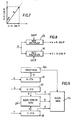
- Fig 7 which illustrates the connection between polar or vector coordinates and cartesian coordinate
- the frequency representing R is supplied to a first rate multiplier 25 and a second rate multiplier 26, the first rate multiplier 25 having as a second input a sin ⁇ value which may be fetched from a look-up table in a read-only memory ROM (shown in figure 11) which is part of the S/D converter 19.
- This frequency signal. is supplied to an X-counter 27 as illustrated in Fig. 9, which converts the frequency signal to a digital counter value pointing to the associated address in the block memory 17a and an associated block pointer memory 29'.
- signals are transferred from the X-counter 27 and the Y-counter 28 to the block pointer memory 29', which during coordinate conversion presents pointers to the block memory 17a.
- Such pointers are also generated when blocks are transferred to the radar display memory 21, and in this case the addresses to block pointer memory are generated in the CPU 20 as illustrated in Fig 3.
- the frequency representing the fundamental vector R is supplied to an R-counter 29 which points to addresses in the sweep memory 16a, which is also represented at 16 in Fig. 3.
- the block memory 17 which has previously been indicated in Fig. 3 and Fig 5. comprises 256 block elements each of which are divided into 16x16 pixels, thereby making a total of 65 536 pixel positions. Each of these pixel points can store a 3-bit information giving a total of 196,608 bits to be stored in the block memory 17.
- Fig. 10 it is schematically illustrated how the various blocks in the block memory 17 are arranged in relation to the writing sweep beam which represents the digitized radar video signals which are intermittently stored in the sweep memory 16 illustrated at 16b in Fig. 10.
- the block memory 17 is addressed in such a way that the sweep memory scanning area is always covered by some or all of the memory blocks included in the block memory 17.
- Fig. 10 there is illustrated an example of a writing sweep beam 16b generated by the sweep memory 16, which passes through four blocks, namely blocks Bl-B6 in the block memory 17b. It is seen that video at position A in the writing sweep beam 16b is written into block B2, pixel 10-3 in the X, Y-plane.
- the sweep beam has a notional bearing ⁇ going through block B4, block B5, block B2 and block B3, the notional bearing corresponding to the actual bearing ⁇ of the radar antenna.
- the writing sweep beam would scan through other blocks and pixels. This notional scanning by the writing sweep beam is in fact effected by the manner in which the block memory 17 is addressed as data is written from the sweep memory 16 to the block memory 17 as will be explained in more detail herein-after.
- the writing sweep beam 16b has already scanned through block Bl and this block has therefore been "filled" with the necessary video data in converted scan format, and is now ready to'be emptied, i.e. the information thereof transferred to the radar memory 21, see Fig. 3.
- block B6 When the writing sweep beam moves further it will come into the area covered by block B6, and block B6 must therefore be an "empty" block. If all the 256 blocks in the block memory are considered, it is seen that some blocks are empty, some occupied by the writing sweep beam, some being emptied and some being filled. It should also be noted that at start-up the pointer memory 29' is initialized with the correct pointers.
- the block memory pixel locations which are covered by the writing sweep beam are filled with data representing raw radar video information in accordance with the cartesian coordinates associated therewith, and the memory blocks containing the pixel locations which are to be filled with information are so arranged as to be "displaceably" overlapped by the sweep beam through its scanning operation.
- the blocks which are in the process of being filled are maintained with an address corresponding to the actual antenna bearing interval, which makes these blocks stationary relative to the writing sweep beam whilst being covered by the same, whereas the blocks which have been passed by the writing sweep beam and are emptied, are displaced i.e. given another address so as to be "positioned" ahead of the writing sweep beam for thereby maintaining the overlapping thereof.
- This overlapping of the blocks on the writing sweep beam is accomplished by the central processing unit 20 indicated in Fig.3, the processing unit 20 receiving bearing information from the antenna.
- This bearing information settles the address of each memory block, so as to correspond to a bearing interval in which the memory blocks are covered by the writing sweep beam.
- the said data is transferred to the radar display memory 21 and the address of the emptied memory block is changed so that this block assumes a "ready" position in order to be covered again by the advancing writing sweep beam.
- the total number of pixels per complete rotation of the radar beam is 4.096.000, the radar pulse repetition rate being 2000 per second. Since the beam rotates in small steps, some elementary areas scanned are irradiated several times during one complete rotation of the beam. All the raw digitized pixels are stored in the block memory 17, but only the final i.e. last pixel data which appears after the beam has passed any particular elementary area is transferred to the radar display refresh memory 3. The passing of the beam is monitored by an algorithm. Thus there are 4.096.000 writing accesses to the block memory 17, but only 1045876 "final" pixels are transferred to the refresh memory 3.
- the central processing unit 20 reads off console-buttons for sweep-centre, range afterglow intensity etc. This information is transferred to the in/out-modules 9 to 13 at initialization.
- the CPU 20 will, as mentioned above, also generate a table in the CPU-memory, which includes all memory block addresses and the corresponding antenna bearings. This table is regenerated every time the sweep centre is moved. In operation the CPU 20 receives an interrupt every ms. When the interrupt is received the CPU 20 reads off the antenna bearing. The block addresses to all blocks which the scan has passed are now output to the video converter output module 12. These addresses are used for transfer of block data from the block memory 17 to the radar display memory 21.
- Fig. 11 there is shown a more detailed block diagram of the video converter input module 11 indicated previously in Fig. 2.
- This module 11 has inter alia circuits for A/D-conversion, interference filter, video sample memory, sine-cosine circuits and XY-rate multipliers. Necessary circuits for range rings, sample select, sync filters and controls are also included.
- the A/D-converter is used to digitize the video signal into eight levels (3-bits), the gain of the converter being a combination of sweep gain and preset gain, and the sample frequency being preferably 24 MHz.
- the sampling frequency is dependent upon range scale setting, and this is accomplished by adjusting the input sample select circuit. Details of the blocks 19 and 18 of Fig.3 are shown in Fig.11 between the legends ANT. SIGNALS and X-CONTROL and Y-CONTROL.
- the bearing information ( ⁇ ) is latched and used as input to a sine-ROM. From the bearing data a sine-value is obtained and from the complement thereof a cosine-value is obtained. Both values are stored. The two most significant bits of the bearing data are decoded for quadrant information. These functions are accomplished by the sine-cosine circuits indicated in Fig. 11.
- the XY-rate multipliers 25 and 26 which have been discussed above, are used to generate the X- and Y-frequencies for coordinate conversion.
- the sine of the bearing value determines X-frequency in quadrants 1 and 3 and Y-frequency in quadrants 2 and 4, whereas the cosine of bearing value determines X-frequency in quadrants 2 and 4 and Y-frequency in quadrants 1 and 3. Both frequencies vary between O and 2 MHz.
- maximum read-frequency in sample memories is preferably 4MHz and maximum XY-frequencies are 2 MHz, it is sometimes during conversion necessary to combine two video cells, i.e. select the biggest of two video values. This is done in the output sample circuit.
- the sync filter circuit has two sync filters, one filter being preset to enable a converter-sync every 0.5 ms, and the other being preset to enable a CPU-sync (sync interrupt) every'l ms. This means that the converter will skip all sync exceeding 2 KHz.
- the enabled sync is synchronized to a 24 MHz clock for data acquisition and to 12 MHz for sine, cosine generation and conversion.
- the module 11 has also circuits for range selection and interface to latch data from a selected bus plane.
- Fig. 12 being a block diagram illustrating the data flow from the coordinate converter unit 2 through the refresh memories 3, 6a-6c and via auxiliary buffers to the monitor 4, and Fig 13 illustrating the monitor timing.
- tha which represents the total active horizontal line time
- pixels for the actual line are shifted from a line buffer 30, 60a, 60b, 60c to the monitor 4 see Fig. 12.
- the refresh memories 3 and 6a, b and c are ready for external inputs of display data.
- the radar data representing a picture line of the monitor, on which the converted radar data is to be displayed is transferred to a line buffer during the horizontal blanking time or flyback period of the monitor 4, and this flyback period is very short compared to the total active horizontal line time.
- a line buffer after the refresh memory allows a rapid transfer of line data during this period because the line data only represents a small quantity of the information stored in the refresh memory.
- the data is transferred in groups, each group being selected so as to have the same row address thereby reducing the access time to each address location by reading the data in page mode and speeding up retrieval and transfer time during the flyback period.
- Page mode reading can be carried out by using for example Intel Memory 2118 elements.
- a selection and timing means for accomplishing the above described transfer of data between the refresh memories and line buffers is indicated by block 31 inscribed REFRESH TIMING in Fig. 12.
- FIG. 14a and 14b A detailed timing diagram is illustrated in Fig. 14a and 14b.
- the principle of the page mode operation can be seen for example from the second group of timing diagrams in Figures 14a and 14b, in which RADO-RAD17 represent address information, R RAS (L) represent Row Address Control Signal (Low), RERAS (H) represent Enable Row address (High), R CAS (L) represent Column Address Signal (Low), EDO (L) represent Enable Data out (Low) and RWE (L) represent Write Enable (L).
- Fig. 15 is a schematic diagram illustrating the pixel positions in the refresh memory, and Fig. 16 illustrates the position of the pixels on the monitor.
- the pixels when the pixels are transferred to the radar display refresh memory they will be stored at locations which correspond to "similar" location in the pixel position of the monitor. This facilitates the transfer of monitor line data from the refresh memory to the line buffer and thence to the monitor via the video output unit illustrated in Fig. 2.
- the central processor 20 reads the antenna bearing every millisecond and, from a simple look-up in the table of bearings with associated block addresses mentioned above, initiates the transferring of the correct data block or blocks. It should be noted that the number of transfers to be initiated will vary from O to a maximum of 64. Each block, as mentioned before, holds 16 x 16 pixels. The transferring of a single block is effected by a continuous sequence of transfer cycles, 4 pixels at a time, giving 64 cycles as the total for one block. The following physical connections are used for the transfer from the block memory 17 to the radar display refresh memory 3:
- control circuitry for the control operation is part of the physical equipment implementing the block memory 17.
Landscapes
- Engineering & Computer Science (AREA)
- Computer Networks & Wireless Communication (AREA)
- Physics & Mathematics (AREA)
- General Physics & Mathematics (AREA)
- Radar, Positioning & Navigation (AREA)
- Remote Sensing (AREA)
- Radar Systems Or Details Thereof (AREA)
Applications Claiming Priority (2)
| Application Number | Priority Date | Filing Date | Title |
|---|---|---|---|
| NO812173A NO149444C (no) | 1981-06-25 | 1981-06-25 | Fremgangsmaate og apparat til behandling av radarinformasjonsdata. |
| NO812173 | 1981-06-25 |
Publications (2)
| Publication Number | Publication Date |
|---|---|
| EP0068852A2 true EP0068852A2 (fr) | 1983-01-05 |
| EP0068852A3 EP0068852A3 (fr) | 1984-04-18 |
Family
ID=19886143
Family Applications (1)
| Application Number | Title | Priority Date | Filing Date |
|---|---|---|---|
| EP82303344A Withdrawn EP0068852A3 (fr) | 1981-06-25 | 1982-06-25 | Procédé et appareil pour le traitement de données indicatives de portée et de site |
Country Status (3)
| Country | Link |
|---|---|
| EP (1) | EP0068852A3 (fr) |
| JP (1) | JPS586479A (fr) |
| NO (1) | NO149444C (fr) |
Cited By (11)
| Publication number | Priority date | Publication date | Assignee | Title |
|---|---|---|---|---|
| FR2542875A1 (fr) * | 1983-03-18 | 1984-09-21 | Thomson Csf | Procede d'adressage de la memoire dans un transformateur numerique d'images |
| GB2169465A (en) * | 1984-12-11 | 1986-07-09 | Mars G B Ltd | Polar to cartesian scan conversion |
| DE3518439A1 (de) * | 1985-05-22 | 1986-11-27 | Siemens AG, 1000 Berlin und 8000 München | Einrichtung zur darstellung von radar-rohvideosignalen und von synthetikdaten |
| FR2589265A1 (fr) * | 1985-10-28 | 1987-04-30 | Descartes Paris V Universite R | Processeur numerique d'images echographiques, a interpolation |
| FR2593624A1 (fr) * | 1986-01-31 | 1987-07-31 | Thomson Csf | Procede d'optimisation de la memorisation de signaux video dans un transformateur numerique d'images, et transformateur numerique d'images mettant en oeuvre un tel procede |
| EP0236177A1 (fr) * | 1986-01-31 | 1987-09-09 | Thomson-Csf | Procédé d'optimisation de la mémorisation de signaux vidéos dans un transformateur numérique d'images, et transformateur numérique d'images mettant en oeuvre un tel procédé |
| FR2596895A2 (fr) * | 1986-04-04 | 1987-10-09 | Thomson Csf | Procede de regulation du debit de sortie de la memoire de blocs d'un transformateur numerique d'images, et transformateur numerique d'images mettant en oeuvre un tel procede |
| FR2614994A1 (fr) * | 1987-05-07 | 1988-11-10 | Thomson Csf | Procede et dispositif de visualisation de plusieurs images radar en une mosaique unique |
| FR2615629A1 (fr) * | 1987-05-22 | 1988-11-25 | Thomson Csf | Procede d'affectation de recurrences radar a des radiales visualisables et transformateur numerique d'images mettant en oeuvre ce procede |
| GB2223640A (en) * | 1986-01-27 | 1990-04-11 | Raytheon Co | Radar video scan converter. |
| CN108663662A (zh) * | 2018-03-06 | 2018-10-16 | 中国船舶重工集团公司第七二四研究所 | 基于gpu的雷达视频信号整体定时刷新贴图显示方法 |
Citations (5)
| Publication number | Priority date | Publication date | Assignee | Title |
|---|---|---|---|---|
| US3531775A (en) * | 1966-09-30 | 1970-09-29 | Fujitsu Ltd | Memory apparatus for rapid write-in and read-out of information |
| US4002827A (en) * | 1975-05-15 | 1977-01-11 | General Electric Company | Polar coordinate format to a cartesian coordinate format scan converter |
| US4053946A (en) * | 1975-11-24 | 1977-10-11 | Hughes Aircraft Company | Modular programmable digital scan converter |
| US4065770A (en) * | 1975-04-17 | 1977-12-27 | The Secretary Of State For Defence In Her Britannic Majesty's Government Of The United Kingdom Of Great Britain And Northern Ireland | Digital scan converters |
| FR2494022A1 (fr) * | 1980-11-12 | 1982-05-14 | Diasonics Inc | Systeme de memoire et de conversion de balayage aux ultrasons ainsi que procede de memorisation et de lecture |
-
1981
- 1981-06-25 NO NO812173A patent/NO149444C/no unknown
-
1982
- 1982-06-25 EP EP82303344A patent/EP0068852A3/fr not_active Withdrawn
- 1982-06-25 JP JP57109667A patent/JPS586479A/ja active Pending
Patent Citations (5)
| Publication number | Priority date | Publication date | Assignee | Title |
|---|---|---|---|---|
| US3531775A (en) * | 1966-09-30 | 1970-09-29 | Fujitsu Ltd | Memory apparatus for rapid write-in and read-out of information |
| US4065770A (en) * | 1975-04-17 | 1977-12-27 | The Secretary Of State For Defence In Her Britannic Majesty's Government Of The United Kingdom Of Great Britain And Northern Ireland | Digital scan converters |
| US4002827A (en) * | 1975-05-15 | 1977-01-11 | General Electric Company | Polar coordinate format to a cartesian coordinate format scan converter |
| US4053946A (en) * | 1975-11-24 | 1977-10-11 | Hughes Aircraft Company | Modular programmable digital scan converter |
| FR2494022A1 (fr) * | 1980-11-12 | 1982-05-14 | Diasonics Inc | Systeme de memoire et de conversion de balayage aux ultrasons ainsi que procede de memorisation et de lecture |
Non-Patent Citations (1)
| Title |
|---|
| IEEE TRANSACTIONS ON COMPUTERS, vol. C-27, no. 2, February 1978, pages 113-125, IEEE, New York, US * |
Cited By (20)
| Publication number | Priority date | Publication date | Assignee | Title |
|---|---|---|---|---|
| FR2542875A1 (fr) * | 1983-03-18 | 1984-09-21 | Thomson Csf | Procede d'adressage de la memoire dans un transformateur numerique d'images |
| US4745475A (en) * | 1984-12-11 | 1988-05-17 | Mars Incorporated | Displays for information obtained by vector scanning |
| GB2169465A (en) * | 1984-12-11 | 1986-07-09 | Mars G B Ltd | Polar to cartesian scan conversion |
| FR2581764A1 (fr) * | 1984-12-11 | 1986-11-14 | Mars G B Ltd | Systeme d'affichage d'informations obtenues par balayage d'antenne tournante |
| FR2587499A1 (fr) * | 1984-12-11 | 1987-03-20 | Mars G B Ltd | Systeme de visualisation sur un ecran d'affichage matriciel de donnees en coordonnees polaires |
| GB2169465B (en) * | 1984-12-11 | 1989-10-04 | Mars G B Ltd | Polar to cartesian scan conversion |
| DE3518439A1 (de) * | 1985-05-22 | 1986-11-27 | Siemens AG, 1000 Berlin und 8000 München | Einrichtung zur darstellung von radar-rohvideosignalen und von synthetikdaten |
| FR2589265A1 (fr) * | 1985-10-28 | 1987-04-30 | Descartes Paris V Universite R | Processeur numerique d'images echographiques, a interpolation |
| EP0230158A1 (fr) * | 1985-10-28 | 1987-07-29 | Universite Rene Descartes (Paris V) | Processeur numérique d'images échographiques, à interpolation |
| GB2223640B (en) * | 1986-01-27 | 1990-10-31 | Raytheon Co | Radar video scan converter |
| GB2223640A (en) * | 1986-01-27 | 1990-04-11 | Raytheon Co | Radar video scan converter. |
| US4740789A (en) * | 1986-01-31 | 1988-04-26 | Thomson-Csf | Method for optimizing the storage of video signals in a digital scan converter, and a digital scan converter using said method |
| EP0236177A1 (fr) * | 1986-01-31 | 1987-09-09 | Thomson-Csf | Procédé d'optimisation de la mémorisation de signaux vidéos dans un transformateur numérique d'images, et transformateur numérique d'images mettant en oeuvre un tel procédé |
| FR2593624A1 (fr) * | 1986-01-31 | 1987-07-31 | Thomson Csf | Procede d'optimisation de la memorisation de signaux video dans un transformateur numerique d'images, et transformateur numerique d'images mettant en oeuvre un tel procede |
| FR2596895A2 (fr) * | 1986-04-04 | 1987-10-09 | Thomson Csf | Procede de regulation du debit de sortie de la memoire de blocs d'un transformateur numerique d'images, et transformateur numerique d'images mettant en oeuvre un tel procede |
| FR2614994A1 (fr) * | 1987-05-07 | 1988-11-10 | Thomson Csf | Procede et dispositif de visualisation de plusieurs images radar en une mosaique unique |
| WO1988008988A1 (fr) * | 1987-05-07 | 1988-11-17 | Thomson-Csf | Dispositif de visualisation de plusieurs images radar |
| FR2615629A1 (fr) * | 1987-05-22 | 1988-11-25 | Thomson Csf | Procede d'affectation de recurrences radar a des radiales visualisables et transformateur numerique d'images mettant en oeuvre ce procede |
| WO1988009514A1 (fr) * | 1987-05-22 | 1988-12-01 | Thomson-Csf | Transformateur numerique d'images radar |
| CN108663662A (zh) * | 2018-03-06 | 2018-10-16 | 中国船舶重工集团公司第七二四研究所 | 基于gpu的雷达视频信号整体定时刷新贴图显示方法 |
Also Published As
| Publication number | Publication date |
|---|---|
| JPS586479A (ja) | 1983-01-14 |
| EP0068852A3 (fr) | 1984-04-18 |
| NO812173L (no) | 1982-12-27 |
| NO149444B (no) | 1984-01-09 |
| NO149444C (no) | 1984-04-25 |
Similar Documents
| Publication | Publication Date | Title |
|---|---|---|
| CA1191238A (fr) | Dispositif de tracage en cartographie | |
| CA1217272A (fr) | Affichage en perspective temps reel utilisant un generateur de cartes numerique | |
| US4876651A (en) | Digital map system | |
| US4586037A (en) | Raster display smooth line generation | |
| US4489389A (en) | Real time video perspective digital map display | |
| US4660157A (en) | Real time video perspective digital map display method | |
| US4065770A (en) | Digital scan converters | |
| US4002827A (en) | Polar coordinate format to a cartesian coordinate format scan converter | |
| US4205389A (en) | Apparatus for generating a raster image from line segments | |
| CA1230407A (fr) | Dispositif et methode de conversion de balayage | |
| US4672369A (en) | System and method for smoothing the lines and edges of an image on a raster-scan display | |
| EP0068852A2 (fr) | Procédé et appareil pour le traitement de données indicatives de portée et de site | |
| US4106021A (en) | Polar to rectangular coordinate converter | |
| JPS61231473A (ja) | デイジタル走査型変換器からの画像への挿入画像挿入方法及びその装置 | |
| US4774516A (en) | Method for smoothing an image generated by coordinate conversion and a digital scan converter using the method | |
| US6496160B1 (en) | Stroke to raster converter system | |
| CA2134041A1 (fr) | Indicateur mixte radar-graphique | |
| US4884220A (en) | Address generator with variable scan patterns | |
| US5351055A (en) | Radar apparatus | |
| US5414429A (en) | Device for converting output data of a radar for the display thereof on a television screen | |
| US4583191A (en) | Scan converter | |
| EP0299666A2 (fr) | Appareil et procédé pour la conversion de balayage | |
| JP2610473B2 (ja) | レーダ装置 | |
| JP3880216B2 (ja) | レーダー装置及び類似装置 | |
| JPS5595145A (en) | Rotating method for pattern |
Legal Events
| Date | Code | Title | Description |
|---|---|---|---|
| PUAI | Public reference made under article 153(3) epc to a published international application that has entered the european phase |
Free format text: ORIGINAL CODE: 0009012 |
|
| AK | Designated contracting states |
Designated state(s): BE FR GB IT NL SE |
|
| PUAL | Search report despatched |
Free format text: ORIGINAL CODE: 0009013 |
|
| AK | Designated contracting states |
Designated state(s): BE FR GB IT NL SE |
|
| STAA | Information on the status of an ep patent application or granted ep patent |
Free format text: STATUS: THE APPLICATION IS DEEMED TO BE WITHDRAWN |
|
| 18D | Application deemed to be withdrawn |
Effective date: 19850319 |
|
| RIN1 | Information on inventor provided before grant (corrected) |
Inventor name: ABELSEN, OLE JOHAN Inventor name: POHNER, FREDDY Inventor name: TORKILSENG, TOR ARNE Inventor name: FOSSAN, MAGNE |