EP0068390A2 - An optical head - Google Patents
An optical head Download PDFInfo
- Publication number
- EP0068390A2 EP0068390A2 EP82105430A EP82105430A EP0068390A2 EP 0068390 A2 EP0068390 A2 EP 0068390A2 EP 82105430 A EP82105430 A EP 82105430A EP 82105430 A EP82105430 A EP 82105430A EP 0068390 A2 EP0068390 A2 EP 0068390A2
- Authority
- EP
- European Patent Office
- Prior art keywords
- light
- objective lens
- optical head
- head according
- receiving surface
- Prior art date
- Legal status (The legal status is an assumption and is not a legal conclusion. Google has not performed a legal analysis and makes no representation as to the accuracy of the status listed.)
- Granted
Links
- 230000003287 optical effect Effects 0.000 title claims abstract description 149
- 210000001624 hip Anatomy 0.000 description 23
- 238000001514 detection method Methods 0.000 description 3
- 238000010586 diagram Methods 0.000 description 3
- 230000007547 defect Effects 0.000 description 2
- 230000004913 activation Effects 0.000 description 1
- 230000002238 attenuated effect Effects 0.000 description 1
- 230000015572 biosynthetic process Effects 0.000 description 1
- 230000003247 decreasing effect Effects 0.000 description 1
- 238000006073 displacement reaction Methods 0.000 description 1
- 230000002093 peripheral effect Effects 0.000 description 1
- 125000006850 spacer group Chemical group 0.000 description 1
Images


Classifications
-
- G—PHYSICS
- G11—INFORMATION STORAGE
- G11B—INFORMATION STORAGE BASED ON RELATIVE MOVEMENT BETWEEN RECORD CARRIER AND TRANSDUCER
- G11B7/00—Recording or reproducing by optical means, e.g. recording using a thermal beam of optical radiation by modifying optical properties or the physical structure, reproducing using an optical beam at lower power by sensing optical properties; Record carriers therefor
- G11B7/08—Disposition or mounting of heads or light sources relatively to record carriers
- G11B7/09—Disposition or mounting of heads or light sources relatively to record carriers with provision for moving the light beam or focus plane for the purpose of maintaining alignment of the light beam relative to the record carrier during transducing operation, e.g. to compensate for surface irregularities of the latter or for track following
- G11B7/0908—Disposition or mounting of heads or light sources relatively to record carriers with provision for moving the light beam or focus plane for the purpose of maintaining alignment of the light beam relative to the record carrier during transducing operation, e.g. to compensate for surface irregularities of the latter or for track following for focusing only
-
- G—PHYSICS
- G11—INFORMATION STORAGE
- G11B—INFORMATION STORAGE BASED ON RELATIVE MOVEMENT BETWEEN RECORD CARRIER AND TRANSDUCER
- G11B7/00—Recording or reproducing by optical means, e.g. recording using a thermal beam of optical radiation by modifying optical properties or the physical structure, reproducing using an optical beam at lower power by sensing optical properties; Record carriers therefor
- G11B7/12—Heads, e.g. forming of the optical beam spot or modulation of the optical beam
- G11B7/135—Means for guiding the beam from the source to the record carrier or from the record carrier to the detector
- G11B7/1372—Lenses
- G11B7/1378—Separate aberration correction lenses; Cylindrical lenses to generate astigmatism; Beam expanders
-
- G—PHYSICS
- G11—INFORMATION STORAGE
- G11B—INFORMATION STORAGE BASED ON RELATIVE MOVEMENT BETWEEN RECORD CARRIER AND TRANSDUCER
- G11B7/00—Recording or reproducing by optical means, e.g. recording using a thermal beam of optical radiation by modifying optical properties or the physical structure, reproducing using an optical beam at lower power by sensing optical properties; Record carriers therefor
- G11B7/12—Heads, e.g. forming of the optical beam spot or modulation of the optical beam
- G11B7/135—Means for guiding the beam from the source to the record carrier or from the record carrier to the detector
- G11B7/1381—Non-lens elements for altering the properties of the beam, e.g. knife edges, slits, filters or stops
Landscapes
- Physics & Mathematics (AREA)
- Optics & Photonics (AREA)
- Optical Head (AREA)
- Optical Recording Or Reproduction (AREA)
Abstract
Description
- The present invention relates to an optical system for reading from and writing information on an information recording and/or reproducing medium such as an optical disk and, more particularly, to an optical head for projecting a laser beam onto an information recording and/or reproducing medium read from and write information on it.
- In an optical system which reads out from or writes information on an information recording and/or reproducing medium, a laser beam are projected onto the information recording and/or reproducing medium (to be referred to as an optical disk hereinafter) through an optical head. The laser beam reflected from the optical disk are picked up by the optical head. In order to write information on the optical disk and read it out therefrom properly, the focal point of an objective lens of the optical head must be accurately placed on the light reflecting surface of the optical disk. In other words, the beam waist of the laser beam converged by the objective lens must be projected onto the optical disk. Various apparatuses have been developed to detect the focal point of the objective lens. However, none of them is satisfactory. For example, an apparatus which utilizes the difference between sizes of focused and unfocused beam spots on the optical disk is proposed wherein different patterns of the focused and unfocused beam spots-are projected onto a photodetector and are detected by the photodetector to achieve proper focusing. Further, an apparatus for focusing a laser beam, which is provided with a lens system combining a convex lens and a cylindrical lens is disclosed in U.S.P. No. 4,079,247 of Bricot et al. In these apparatuses, if minuteness recess or projections are formed on the optical disk, a diffraction pattern is formed in the beam spot pattern on the photodetector, resulting in erroneous operation. Especially, in an optical disk which has a tracking guide to increase information recording capacity, a diffraction pattern of the tracking guide is formed in the beam spot pattern on the photodetector when the beam spot is formed on the tracking guide. As a result, the apparatus may be erroneously operated.
- In the apparatus described above, the out-of-focus state of the objective lens is detected by changes in the size of the beam spot pattern on the photodetector or in the shape of the beam spot pattern. Another apparatus is proposed which detects the out-of-focus state of the objective lens by a location of a beam spot pattern formed on a photodetector. In this apparatus, laser beam for detecting the out-of-focus state of the objective lens are incident on the objective lens parallel to an optical axis of the objective lens and projected onto the optical disk therethrough, in addition to laser beams which are used for readout and writing of information. However, it has a drawback that an optical system becomes complex and the apparatus is manufactured at high cost, because the optical system having at least two optical paths for the laser beams is required. Other apparatuses are disclosed in Japanese Patent Disclosure Nos. 53-28,405, 49-31,128, and 53-10,407, respectively.
- In these apparatuses, laser beams for reading out and writing information are not travelled on an optical axis of an-objective lens but are travelled in parallel to the axis thereof. However, in these apparatuses the laser beams cannot be sufficiently converged by the objective lens, and a sufficiently small beam spot cannot be formed on the optical disk. Further, since the laser beams pass through the outer peripheral portion of the objective lens and are projected onto the optical disk, the intensity of laser beams projected onto the optical disk is decreased by eclipse.
- Further, an apparatus is dislosed in Japanese Patent Disclosure No. 53-118,103, in which a prism is arranged on an optical path of laser beams reflected by an optical disk. In this apparatus, the intensity of the laser beams may be attenuated when they pass through the prism, and unwanted diffraction may occur.
- It is, therefore, an object of the present invention to provide an optical system for accurately detecting the focusing state of an objective lens.
- It is another object of the present invention to provide an optical system which accurately detects the focusing state of the objective lens and which simultaneously accurately traces a tracking guide.
- In order to achieve the above objects of the present invention, there is provided an optical head for focusing light beam on a light reflecting surface, comprising:
- means for generating the light beam;
- means for transferring the light beam;
- an objective lens for converting the light beam transferred by said transferring means to convergent light beam having a beam waist, for projecting the convergent light beam onto the optical plane, and for converging divergent light beam reflected from the light reflecting surface;
- a projection lens for converging the light beam from said objective lens;
- means for deflecting the convergent light beam projected from said projection lens, depending on a distance between said objective lens and the light reflectively surface; and
- a photodetector provided with a light-receiving surface arranged on an image forming plane on which an image of a beam waist of the convergent light beam is formed by said objective and projection lenses when the convergent light beam are projected through said projection lens onto said photodetector on which a projected pattern is formed, and when said objective lens is spaced apart from the light reflecting surface at a predetermined distance and the beam waist of the convergent light beams is formed on the light reflecting surface, said light-receiving surface comprising first and second photosensitive regions, and said first and second photosensitive regions being arranged in a direction along which a projected pattern formed by the light beams on said light-receiving surface is shifted by said deflecting means.
- This invention can be more fully understood from the following detailed description when taken in conjunction with the accompanying drawings, in which:
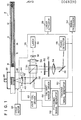
- Fig. 1 is a schematic block diagram of an optical system having an optical head according to one embodiment of the present invention;
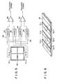
- Fig. 2 is a perspective view showing a model of the optical system of the optical head shown in Fig. 1;
- Figs. 3A, 3B and 3C are views for explaining optical paths of the laser beams in the optical system shown in Fig. 2;
- Figs. 4A, 4B and 4C show image patterns formed on a light-receiving surface of a photodetector when the laser beams pass through the optical paths shown in Figs. 3A, 3B and 3C, respectively;
- Fig. 5 is a block diagram of a focusing signal generator and a tracking signal generator which are connected to the photodetector shown in Figs. 4A, 4B and 4C;
- Fig. 6 is a perspective view of laser beam spots formed by the laser beams projected onto a light-reflecting surface of the optical disk;
- Figs. 7A, 7B and 7C are plan views of the light-receiving surface of the photodetector, showing images of the tracking guide which are formed in the images of the laser beam spots and diffraction patterns in the tracking guide;
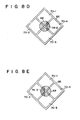
- Figs. 8A to 8E are plan views of a light-receiving surface of a photodetector having photosensitive regions whose arrangement is different from that of the light-receiving surface of the photodetector shown in Figs. 4A to 4C and Figs. 7A to 7C, showing the images of the laser beam spots formed on the light-receiving surface and projected patterns of the laser beams;
- Fig. 9 is a block diagram of a focusing signal generator and a tracking signal generator which are connected to the photodetector shown in Figs. 8A to 8E;
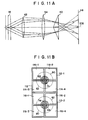
- Figs. 10, llA, 12 and 13 show an optical head of an optical system which differs from the optical head of the optical system shown in Figs. 1 and 2 according to another embodiment of the present invention; and
- Fig. 11B is a plan view of the light-receiving surface of the photodetector according to the optical system shown in Fig. 11A.
- Fig. 14 is a perspective view of laser beam paths and laser beam spots in the optical system shown in Fig. 13.
- Referring to Fig. 1, information is read out from or written on an
optical disk 2 as the information recording and/or reproducing medium. Theoptical disk 2 comprises a pair of disk-shapedtransparent plates outer spacers - Light-reflecting
layers transparent plates layers optical disk 2. When theoptical disk 2 is placed on aturntable 18, a center spindle 20 of theturntable 18 is fitted into the through hole of theoptical disk 2, such that the rotational center of theturntable 18 is aligned with that of theoptical disk 2. Achucking element 22 is mounted on the spindle 20. Theoptical disk 2 is fixed on theturntable 18 by thechucking element 22. Theturntable 18 is rotatably supported by a support member (not shown) and is driven at a constant speed by adrive motor 24. - The optical system shown in Fig. 1 has an
optical head 26 to project laser beam onto the surface of the light-reflectinglayer 14 of theoptical disk 2 and to write information on or read it out from theoptical disk 2. Theoptical head 26 is radially movable along theoptical disk 2 by alinear actuator 28 and has alaser 30 for generating laser beams. For writing information on theoptical disk 2, laser beam of modulated intensity is generated from thelaser 30. For reading out information from theoptical disk 2, laser beam having a predetermined intensity is generated from thelaser 30. The laser beam generated from thelaser 30 are diverged by aconcave lens 32 and converted to parallel laser beam by aconvex lens 34. The parallel laser beam is then transmitted through abeam splitter 36 and are incident on agalvano mirror 38. The laser beam is then reflected by thegalvano mirror 38, are transmitted through aquarter wave plate 40, are converged by anobjective lens 42, and projected onto the surface of the light-reflectinglayer 14 of theoptical disk 2. Theobjective lens 42 is movably supported byvoice coils 44 along an optical axis of theobjective lens 42. When the focal point of theobjective lens 42 is located on the surface of the light-reflectinglayer 14 of theoptical disk 2 by activation of the voice coils 44, a smallest beam spot corresponding to a beam waist of the laser beam is formed on the light-reflectinglayer 14. Meanwhile, for writing information on the light-reflectinglayer 14, pits are formed along the tracking guide on the light-reflectinglayer 14 by intensity-modulated laser beam. Information is recorded in the form of pits on the tracking guide. For reading out information from the light-reflectinglayer 14, the light beam is intensity-modulated by the pits formed along the tracking guide. - Laser beam reflected from the light-reflecting
layer 14 is guided to thegalvano mirror 38 through theobjective lens 42 and thequarter wave plate 40. The laser beam reflected by thegalvano mirror 38 is incident on thebeam splitter 36. It pass through thequarter wave plate 40 twice until it is transmitted through thebeam splitter 36 and are directed toward theoptical disk 2, where it is reflected from theoptical disk 2 and returned to thebeam splitter 36. Therefore, the laser beam returned to thebeam splitter 36 is half-phase retarded from the laser beam directed toward theoptical disk 2. As a result, the laser beam returned to thebeam splitter 36 is reflected and is directed toward amirror 46. The laser beam is then reflected by themirror 46 and is incident on thephotodetector 48. Thus, an image corresponding to the beam spot on the light-reflectinglayer 14 is formed on thephotodetector 48. Anaperture stop 50, a light-shieldingplate 52 having an aperture, a slit or a knife edge, and aprojection lens 54 for projecting the laser beams onto thephotodetector 48 are arranged between thebeam splitter 36 and themirror 46. The laser beam is converted to a photoelectric signal by aphotodetector 48, which is then processed in asignal processor 56 and converted to digital information or data. The photoelectric signal is also supplied to a focusingsignal generator 58 and to atracking signal generator 60 which respectively generate a focusing signal and a tracking signal after processing of the received signal. The focusing signal is supplied to avoice coil driver 62 to drive the voice coils 44. Thus, theobjective lens 42 is moved along the optical axis thereof, and the position of the focal point of theobjective lens 42 is adjusted. On the other hand, the tracking signal is supplied to agalvano mirror driver 64 to adjust the inclination of thegalvano mirror 38. As a result, the laser beam is directed toward the tracking guide and the beam spot is accurately positioned along the tracking guide on the light-reflectinglayer 14. - In the
optical head 2 described above, the beam waist of the laser beam converged by theobjective lens 42 is positioned on the light-reflectinglayer 14. The relative positional relationship between theobjective lens 42, theprojection lens 54 and thephotodetector 48 is so determined that a smallest beam spot is formed on the light-reflectinglayer 14 and its image is formed on the light-receiving surface of thephotodetector 48. As shown in Fig. 1, since the parallel laser beam is generally incident on theobjective lens 42, the beam waist is formed at the focal point of theobjective lens 42. When theobjective lens 42 is adjusted in focus state, a distance between theobjective lens 42 and the light-reflectinglayer 14 is determined to be a focal length of theobjective lens 42, and the smallest beam spot, corresponding to the beam waist, is formed on the light-reflectinglayer 14. The diverged laser beam reflected by the smallest beam spot at the focal point are converted to parallel laser beam by theobjective lens 42 and are transmitted to theprojection lens 54. The parallel beams are converged by theprojection lens 54 and focused onto the focal point thereof. Therefore, the smallest beam spot image is formed at the focal point of theprojection lens 54, and the light-receiving surface of the photodetector .48 is positioned at the focal point of theprojection lens 54. Although parallel laser beam is transmitted to theobjective lens 42 from theconvex lens 34, the laser beam need not be parallel; slightly diverged or converged laser beam may be incident on theobjective lens 42. When this occurs, the beam waist is not formed at the focal point of theobjective lens 42 but is formed near the focal point. In this case, when the beam waist is positioned on the light-reflectingsurface 14 and the beam waist is formed on the light-reflecting surface, theobjective lens 42 is kept in the in-focus state. The image of the smallest beam spot is not formed at the focal point of theprojection lens 54 but near the focal point. - The mode of operation for determining by the
optical head 26 whether theobjective lens 42 is in the in-focus state or out-of-focus state will be described with reference to Figs. 2, 3A, 3B and 3C. In Figs. 2,-3A, 3B and 3C, the optical system from theoptical disk 2 to thephotodetector 48 shown in Fig. 1 is simplified for illustrative convenience. If theobjective lens 42 is in the in-focus state, as shown in Figs. 2 and 3A, the light-receivingsurface 66 of thephotodetector 48 is positioned on an image forming plane of the beam spot determined by the position and the focal length of theobjective lens 42. Therefore, an image 68 (Fig. 4A) of the smallest beam spot corresponding to the beam waist is formed on the light-receiving surface 66 (Fig. 4A) of thephotodetector 48 by the laser beam component passing through the light-shieldingplate 52. The light-receivingsurface 66 of thephotodetector 48 comprises four rectangular photosensitive regions 70-1, 70-2, 70-3-and 70-4. The center of the photosensitive surface is aligned with anoptical axis 73 of theprojection lens 54. If the trackingguide 71 extends on the light-reflectinglayer 14 of theoptical disk 2 in the direction indicated by anarrow 72, an image 7.4 (Fig. 4A) of the tracking guide is formed within theimage 68 of the beam spot. Theimage 74 extends in the direction indicated by anarrow 76. The four photosensitive regions 70-1, 70-2, 70-3 and 70-4 (Fig. 4A to 4C) are arranged along the direction indicated by thearrow 76 and the direction indicated by anarrow 78 which is perpendicular to the direction indicated by thearrow 76. The light-shieldingplate 52 is perpendicular to theoptical axis 73 of theprojection lens 54 and is positioned at Fourier transformer plane determined by theprojection lens 54. The aperture of the light-shieldingplate 52, defined as the light-transmitting region, is deviated from theoptical axis 73. Therefore, as shown in Fig. 3B, if theobjective lens 42 comes too close to the light-reflectinglayer 14 of theoptical disk 2, a laser beam pattern 80 (Fig. 4B) projected from theprojection lens 54 is formed on the photosensitive regions 70-1 and 70-2, as shown in Fig. 4B. In other words, if theobjective lens 42 comes too close to the light-reflectinglayer 14, the beam waist is formed by the laser beam reflected from the light-reflectinglayer 14 and a beam spot whose diameter is larger than the smallest beam spot is formed on the light-reflectinglayer 14. Thus the beam waist is formed between theobjective lens 42 and its focal point. Therefore, the laser beam directed from the beam waist to theobjective lens 42 are converted to diverged laser beam by theobjective lens 42 and are projected onto the light-shieldingplate 52. Since the laser beam component passing through the light-shieldingplate 52 is divergent, this component cannot be projected at the center of -the light-receivingsurface 66 of thephotodetector 48 despite being converged by theprojection lens 54. The laser beam component is deviated in the direction indicated by thearrow 76 and is projected onto the photosensitive regions 70-1 and 70-2 to form a projectedpattern 80. Conversely, as shown in Fig. 3C, if theobjective lens 42 is too far away from the light-reflectinglayer 14 of theoptical disk 2, a laser beam pattern 82 (Fig. 4C) projected through theprojection lens 54 is formed in the photosensitive regions 70-3 and 70-4. In other words, if theobjective lens 42 is placed too far away -from the light-reflectinglayer 14, the divergent laser beam from the beam waist is incident on the light-reflectinglayer 14, and a beam spot whose diameter is larger than the smallest beam spot is formed. The laser beam from this beam spot to theobjective lens 42 are converted to converging laser beams by theobjective lens 42 and are directed toward the light-shieldingplate 52. The converging laser beams passing through the light-shieldingplate 52 are converged by theprojection lens 54 to form a beam waist. Thereafter, the beams are diverged again and are projected onto the photosensitive regions 70-3 and 70-4. - As is apparent from the above description, if the
objective lens 42 is in the in-focus state, that area of the beam spot image which is formed in the photosensitive regions 70-1 and 70-2 will be equal to that area of the same beam spot image which is formed in the photosensitive regions 70-3 and 70-4, as shown in Fig. 4A. The photoelectric signal level generated from the photosensitive regions 70-1 and 70-2 will be equal. to the photoelectric signal level generated from the photosensitive regions 70-3 and 70-4. Therefore, in a focusingsignal generator 58 shown in Fig. 5, an output signal from anadder 84 connected to the photosensitive regions 70-1 and 70-2 will be at the same level as that from anadder 86 connected to the photosensitive regions 70-3 and 70-4. Thus, acomparator 88 connected to theadders region 66, a photoelectric signal is generated only by the photosensitive regions 70-1 and 70-2 and thevoice coil driver 62 is activated. As a result, theobjective lens 42 is moved in the direction away from theoptical disk 2 by the voice coils 44. However, as shown in Fig. 4C, if the projected pattern corresponding to the diffraction pattern of the beam spot is formed on the light-receivingsurface 66, the objective lens is moved toward theoptical disk 2 in response to the focusing signal from thecomparator 88. - The operation for tracing the tracking guide on the light-reflecting
layer 14 of theoptical disk 2 with the laser beam, that is, the tracking operation, will be described with reference to Figs. 2 and 6, and Figs. 7A to 7C. When thegalvano mirror 38 shown in Fig. 1 is inclined, the laser beams reflected from thegalvano mirror 38 are also reoriented. A laser beam spot 67 (Fig. 2) formed on the light-reflecting layer is moved in the direction indicated by thearrow 90 which is perpendicular to that indicated by thearrow 72 along which the tracking guide extends. The smallest beam spot 67 has a diameter larger than a . width of theadjacent tracking guide 71. As shown in Fig. 6, if a smallest beam spot 67-1 is properly projected onto a tracking guide 71-1, an image 74-1 of a tracking guide 71-1 is formed within an image 68-1 of the smallest beam spot 67-1 on the light-receivingsurface 66 of thephotodetector 48, as shown in Fig. 7A. However, if smallest beam spots 67-2 and 67-3 are not properly projected onto tracking guides 71-2 and 71-3 and only parts of the beam spots 67-2 and 67-3 are formed on the tracking guides 71-2 and 72-3, respectively, only parts of images 74-2 and 74-3 of the tracking guides 71-2 and 71-3 are formed in images 68-2 and 68-3 of the smallest beam spots 67-2 and 67-3, respectively, as shown in Figs. 7B and 7C. If light rays are incident on the tracking guides 71-1 to 71-3, the light rays are diffracted at the edges of the tracking guides 71-1 to 71-3. Therefore, the images 68-1, 68-2 and 68-3 of the tracking guides 71-1, 71-2 and 71-3 are less bright than images formed between the tracking guides, resulting in the formation of dark regions. Therefore, as shown in Fig. 7A, when the smallest beam spot 67-1 is properly projected onto the tracking guide 71-1, and the image 74-1 of the tracking guide 71-1 is formed on the light-receivingsurface 66, the brightness of the photosensitive regions 70-1 and 70-3 is substantially the same as that of the photosensitive regions 70-2 and 70-4. However, if the smallest beam spots 67-2 and 67-3 respectively are not properly projected onto the tracking guides 71-2 and 72-3 shown in Figs. 7B and 7C, and if only parts of the images 74-2 and 74-3 of the tracking guides 71-2 and 71-3 are formed, the brightness of the photosensitive regions 70-1 and 70-3 is not the same as, that is, larger or smaller than that of the photosensitive regions 70-2 and 70-4. However, when the image 74-1 of the tracking guide 71-1 is properly formed on the light-receivingsurface 66, as shown in Fig. 7A, an output signal from anadder 92 connected to the photosensitive regions 70-1 and 70-3 has substantially the same level as an output signal from anadder 94 connected to the photosensitive regions 70-2 and 70-4. Thus, no tracking signal is generated from acomparator 96. However, when the image 74-2 of the tracking guide 71-2 is formed on the photosensitive regions 70-2 and 70-4, as shown in Fig. 7B, an output signal level of theadder 94 is lower than that of theadder 92, so that thecomparator 96 generates a tracking-signal and the laser beam is shifted to separate in the opposite direction to that indicated by thearrow 90 in Fig. 2 by thegalvano mirror 38, which is driven by thegalvano mirror driver 64. Thus, the beam spot 67 is properly formed on the trackingguide 71. However, if the image 74-3 of the tracking guide 71-3 is formed on the photosensitive regions 70-1 and 70-3, as shown in Fig. 3C thegalvano mirror driver 64 is activated in response to the tracking signal from thecomparator 96 such that the laser beam is moved along the direction indicated by thearrow 90 by thegalvano mirror 38. - - In the optical head shown in Fig. 1, the
galvano mirror 38 moves the laser beam spot in the direction perpendicular to the trackingguide 71. However, theobjective lens 42 may be moved, perpendicularly to its optical axis to move the laser beam spot, instead of thegalvano mirror 38. Alternatively, another mechanism may be employed to move the laser beam spot across the trackingguide 71. In Figs. 7A to 7C, the images 74-1, 74-2 and 74-3 of the tracking guides 71-1, 71-2 and 71-3 are respectively formed on the light-receivingsurface 66 when theobjective lens 42 is kept in the in-focus state. However, as shown in Figs. 4B and 4C, when the projectedpatterns guide 71 are formed within the projected patterns, respectively. The diffraction patterns 74-4 and 74-6 are darker than other regions in the images of the tracking guides. Therefore, even if theobjective lens 42 is not in the in-focus state, it can be detected whether or not the beam spot is properly formed on the trackingguide 71. - As is apparent from the comparison between illustrations in Figs. 4A to 4C and Figs. 7A to 7C, movement of the projected pattern in the direction indicated by the
arrow 76 allows detection of the focusing state of theobjective lens 42. Changes in brightness in the direction indicated by thearrow 78 allow tracking. Thus, focus detection and tracking are independently performed. - The
aperture stop 50 is arranged between theprojection lens 54 and theobjective lens 42 to properly detect the focusing state of theobjective lens 42 and to trace the tracking guide, as shown in Fig. 1. The beam spot 67 on the light-reflectinglayer 14 is distinctly bright. If image information of the beam spot 67 is transferred by theobjective lens 42 and an image corresponding to this image information is formed on the light-receivingsurface 66, animage 68 of the beam spot is neither bright nor distinctive. As a result, focus detection and tracking operation may not be properly performed. However, when theaperture stop 50 is arranged so that a Fourier pattern of high order resulting from Fourier transform of the image of the beam spot by theobjective lens 42 can be shielded by theaperture stop 50. As a result, theimage 68 of the beam spot is distinctly formed on the light-receivingsurface 66. The diameter of theaperture stop 50 is preferably about 40 to 95% of the diameter of the laser beams incident on theaperture stop 50. - The photosensitive regions 70-1, 70-2, 70-3 and 70-4 of the
photodetector 48 may be arranged as shown in Fig. 8A. In this arrangement, the direction indicated by thearrow 76 in which theimage 74 of the trackingguide 71 is moved need not be accurately perpendicular to the direction indicated by thearrow 78 in which the diffraction patterns 74-4 and 74-6 of the trackingguide 71 or of theimage 74 of the trackingguide 71 are moved. Therefore, for arranging thephotodetector 48 in the optical system shown in Fig. 1, the light-receivingsurface 66 need not be given a highly precise orientation with respect to the optical axis of theprojection lens 54. The light-receivingsurface 66 shown in Fig. 8A is arranged on the image forming plane of the smallest beam spot formed on the light-reflectinglayer 14 in correspondence with the beam waist determined by theobjective lens 42 and theprojection lens 54. The pair of photosensitive regions 70-1 and 70-3 for detecting the focusing state of theobjective lens 42 are arranged along the direction indicated by thearrow 76 along which theimage 68 of the beam spot or the projectedpatterns patterns image 74 of the tracking guide in theimage 68 of the beam spot is moved. The pair of photosensitive regions 70-1 and 70-3 are connected to acomparator 88 for generating the focusing signal, while the pair of photosensitive regions 70-2 and 70-4 are connected to acomparator 96 for generating the tracking signal. If the light-reflectinglayer 14 is too close to theobjective lens 42 as shown in Fig. 3B, the projectedpattern 80 shown in Fig. 8B is formed on the light-receivingsurface 66. However, if the light-reflectinglayer 14 is too far away from theobjective lens 42, as shown in Fig. 3C, the projectedpattern 82 shown in Fig. 8C is formed on the light-receivingsurface 66. However, if theobjective lens 42 is in the in-focus state, theimage 68 of the smallest beam spot is formed on the light-receivingsurface 66, as shown in Fig. 8A. If the beam spot is deviated from the trackingguide 71, as shown in Figs. 8D and 8E, theimage 74 of the trackingguide 71 or the diffraction patterns 74-4 and 74-5 of the trackingguide 71 are formed predominantly on one of the photosensitive regions 70-2 and 70-4. In response to the focusing signal and the tracking signal from thecomparators objective lens 42 is set in the in-focus state, while the laser beam spot 67 is accurately moved on the trackingguide 71. Theimages 68 of the beam spots and the projected patterns 74-4 and 74-5 are formed using the light-shieldingplate 52 as the slit. As shown in Figs. 8B and 8C, the projected patterns 74-4 and 74-5 which differ from those shown in Figs. 4B and 4C are formed on the light-receivingsurface 66. - In the above embodiment, in order to move the pattern of the laser beam projected on the light-receiving
surface 66 in accordance with a distance between theobjective lens 42 and the light-reflectinglayer 14, only part of the laser beam which pass through that area deviated from the optical axis extending between theobjective lens 42 and theprojection lens 54 is picked up by the light-shieldingplate 52. In addition to the optical system having the light-shieldingplate 52 which only passes part of the laser beams, other optical systems shown in Figs. 10, 11A, 12, 13 and 14 can change the direction of the laser beam directed from theprojection lens 54 to thephotodetector 48 in accordance with a distance between theobjective lens 42 and the light-reflectinglayer 14. In the optical systems shown in Figs. 10 to 12, the tracking operation can be performed in the same manner as in the optical systems described above, therefore a detailed description thereof will be omitted. - In the optical system shown in Fig. 10, an
objective lens 42 and theprojection lens 54 are arranged so that anoptical axis 104 of theobjective lens 42 crosses anoptical axis 106 of theprojection lens 54. The surface of the light-reflectinglayer 14 is perpendicular to theoptical axis 104 of theobjective lens 42, while the surface of the light-receivingsurface 66 of thephotodetector 48 is perpendicular to theoptical axis 106 of theprojection lens 42. The laser beam with a beam diameter corresponding to the diameter of theobjective lens 42 are incident thereon along theoptical axis 106 of theprojection lens 54. Therefore, if theobjective lens 42 is in the in-focus state, the laser beams projected through theobjective lens 42 form the smallest beam spot corresponding to the beam waist on the light-reflectinglayer 14. As indicated by the solid lines, the laser beam reflected by the light-reflectinglayer 14 are directed toward theobjective lens 42. The laser beam transmitted through theobjective lens 42 is converted to parallel laser beam and converged by theprojection lens 54. The converted laser beam is then projected on the light-receivingsurface 66 positioned on the image forming plane determined by the objective andprojection lenses surface 66. However, if theobjective lens 42 is in the out-of-focus state, the laser beam is guided along the optical path indicated by the broken lines and the alternate long and short dashed lines, projected through theprojection lens 54 and directed toward the light-receivingsurface 66. Therefore, the projected pattern shown in Figs. 4B and 4C is formed on the light-receivingsurface 66. - In the optical system shown in Fig. 11A, the
objective lens 42, theprojection lens 54 and aFresnel biprism 110 are arranged along a commonoptical axis 108. The light-reflectinglayer 14 and a light-receivingsurface 112 of thephotodetector 48 are perpendicular to theoptical axis 108. The light-receivingsurface 112 is positioned on the image forming plane determined by theobjective lens 42 and theprojection lens 54. As shown in Fig. 11B, the light-receivingsurface 112 has two segment surfaces 112-1 and 112-2. The segment surfaces 112-1 and 112-2 have photosensitive regions 114-1, 114-2, 114-3 and 114-4 and photosensitive regions 116-1, 116-2, 116-3 and 116-4, respectively, in the same manner as the light-receivingsurface 66 shown in Fig. 4A. In the optical system shown in Fig. llA, if theobjective lens 42 is in the in-focus state, the parallel laser beam is converged by theprojection lens 54 as indicated by the solid lines, and are split by thebiprism 110. The split laser beams are projected on the light-receivingsurface 112. Therefore, as shown in Fig. 11B, the smallestbeam spot images 68 are formed on the segment surfaces 112-1 and 112-2 of the light-receivingsurface 66, respectively. However, if theobjective lens 42 is in the out-of-focus state, the converged laser beam indicated by the broken lines or diverged laser beam indicated by the alternate long and short dashed lines is incident on theprojection lens 54. The converged laser beam is converged by theprojection lens 54, so that the beam waist thereof is formed between thebiprism 110 and the light-receivingsurface 112. As a result, a pair of projectedpatterns 80 which are spaced apart are formed on the light-receivingsurface 112, as indicated by the broken lines. On the other hand, the diverged laser beam is converted to converged laser beam by theprojection lens 54. In this case, the beam waist is not formed between thebiprism 110 and thelight receiving surface 112 and the laser beams are projected on the light-receivingsurface 112. Therefore, a pair of projectedpatterns 82 which are close together as indicated by the alternate long and short dashed lines are formed on the light-receivingsurface 112, as shown in Fig. 11B. - In the optical system shown in Fig. 12, a
mirror 118 is arranged on the commonoptical axis 108 of the objective andprojection lenses covergent lens 120 having anoptical axis 122 is arranged between themirror 118 and thelight receiving surface 66 of thephotodetector 48. Themirror 118 is arranged on the image forming point determined by theobjective lens 44 and theprojection lens 54 and the light receiving surface of the photodetector arranged on theoptical axis 122. If theobjective lens 42 is in the in-focus-state, the laser beam passes through the optical path indicated by the solid lines and the smallest beam spot image is formed on themirror 118. The smallest beam spot image on the mirror is transferred by theconvergent lens 120 to the light-receivingsurface 66. However, if theobjective lens 42 is in the out-of-focus state, converged laser beam indicated by the broken lines or diverged laser beam indicated by the alternate long and short dashed lines is incident on theprojection lens 54 in the same manner as in the previous embodiments. These laser beams are converged by theprojection lens 54 and the laser beams reflected from themirror 118 is directed to theconvergent lens 120. However, when these laser beams reflected from themirror 118 are converged by theconvergent lens 120, projection patterns shown in Figs. 4B and 4C are formed on the light-receivingsurface 66 due to different travelling directions, respectively. - In the optical system shown in Figs. 13 and 14, the objective and
projection lenses optical axis 108. In the optical system shown in Figs. 13 and 14, first andsecond laser beams objective lens 42. Thefirst laser beam 124 for recording and reproducing the information is travelled along theoptical axis 108 and thesecond laser beam 126 for focusing and tracking thelaser beam 124 is travelled along aoptical path 108 which is remote from, and is parallel with theoptical axis 108. On thelight reflecting layer 14, two beam spots are formed by the two beams as shown in Fig. 14. When theobjective lens 42 is in the in-focus-state, the smallest beam spots corresponding to the beam waists of the twolaser beams light reflecting layer 14. Therefore, the first andsecond laser beams light receiving surface 66 of thephotodetector 48, only the first laser beam being indicated by the solid line. When theobjective lens 42 is in the out-of-focus state, the beam spots larger than the smallest beam spots are formed on thelight receiving surface 66. Thefirst laser beam 124 forms the projected pattern on the center region of thelight receiving surface 66, but thesecond laser beam 126 passing through the optical paths indicated by the broken line or the alternate long and short dashed line is deviated on thelight receiving surface 66 and forms the projected pattern on the upper or lower regions of thelight receiving surface 66. Therefore, the optical system shown in Figs. 13 and 14 can detect the focusing state of the objective lens. In Fig. 14, the tracking guide is formed as a recess on the light reflecting layer instead of the projected tracking guide. - In the embodiments shown in Figs. 10, 11, 12, 13 and 14 the laser beams travelling toward the
objective lens 42 are parallel laser beams. However, converged or diverged laser beams may be used to detect the focusing state of the objective lens in the same manner as in the optical system indicated in Fig. 1. - Explanation has been made in connection with the embodiment in which the optical disk is equipped with a tracking guide and the tracking guide image is formed on the light receiving surface of the photodetector. In this connection it is to be noted that, even if the optical disk is not equipped with the tracking guide, an image corresponding to the tracking guide image is formed on the light receiving surface. That is, where the optical disk is rotated at high speeds, information pits formed on the light reflecting layer of the optical disk describes a pattern as a rotation locus which is similar to that of the tracking guide, permitting a corresponding image to be formed on the light receiving surface. It is to be noted in this connection that in this specification the locus pattern corresponding to the information pits is treated as the tracking guide.
- According to this invention, during the in-focus state of the objective lens the light reflecting layer of the optical disk and light receiving surface of the photodetector are located at the objective point and focal point as determined by the objective lens and projective lens, respectively, permitting an image on a minimum beam spot corresponding to a beam waist to be formed on the light receiving surface. Even if the light reflecting layer of the optical disk is inclined and thus ceases to be in an orthogonal relation to the optical axis of an objective lens, judgement can be made as to whether or not the objective lens is exactly in the in-focus state without causing the beam spot image to be displaced on the light receiving surface. Even when dirt or defect is present on the laser beam path of the optical system, a beam spot image is formed on the image forming point during the in-focus state of the objective lens without involving any displacement of the beam spot image by the dirt or defect. Where the light shielding plate is arranged in a Fourier transform plane as defined by the projection lens, no pattern on the light ray transmitting area on the light shielding plate emerges on the light receiving area during the in-focus state of the objective lens, permitting the in-focus state to be accurately detected.
Claims (19)
Applications Claiming Priority (10)
| Application Number | Priority Date | Filing Date | Title |
|---|---|---|---|
| JP96198/81 | 1981-06-22 | ||
| JP56096198A JPS57210455A (en) | 1981-06-22 | 1981-06-22 | Out-of-focus detecting method |
| JP56146541A JPS5848236A (en) | 1981-09-17 | 1981-09-17 | Optical head |
| JP14654481A JPS5848239A (en) | 1981-09-17 | 1981-09-17 | Optical head |
| JP14654581A JPS5848240A (en) | 1981-09-17 | 1981-09-17 | Optical head |
| JP146541/81 | 1981-09-17 | ||
| JP146545/81 | 1981-09-17 | ||
| JP146544/81 | 1981-09-17 | ||
| JP56168963A JPS5870431A (en) | 1981-10-22 | 1981-10-22 | Optical head |
| JP168963/81 | 1981-10-22 |
Publications (3)
| Publication Number | Publication Date |
|---|---|
| EP0068390A2 true EP0068390A2 (en) | 1983-01-05 |
| EP0068390A3 EP0068390A3 (en) | 1985-01-09 |
| EP0068390B1 EP0068390B1 (en) | 1990-08-22 |
Family
ID=27525777
Family Applications (1)
| Application Number | Title | Priority Date | Filing Date |
|---|---|---|---|
| EP82105430A Expired EP0068390B1 (en) | 1981-06-22 | 1982-06-21 | An optical head |
Country Status (3)
| Country | Link |
|---|---|
| US (1) | US4517666A (en) |
| EP (1) | EP0068390B1 (en) |
| DE (1) | DE3280232D1 (en) |
Cited By (3)
| Publication number | Priority date | Publication date | Assignee | Title |
|---|---|---|---|---|
| EP0070552A2 (en) * | 1981-07-20 | 1983-01-26 | Kabushiki Kaisha Toshiba | Optical head |
| EP0075192A2 (en) * | 1981-09-17 | 1983-03-30 | Kabushiki Kaisha Toshiba | An optical head |
| EP0253613A2 (en) * | 1986-07-14 | 1988-01-20 | Sharp Kabushiki Kaisha | Optical head |
Families Citing this family (27)
| Publication number | Priority date | Publication date | Assignee | Title |
|---|---|---|---|---|
| JPS5911551A (en) * | 1982-07-12 | 1984-01-21 | Toshiba Corp | Optical information storage medium |
| US4654515A (en) * | 1983-05-28 | 1987-03-31 | Kabushiki Kaisha Toshiba | Optical head for focussing a light beam on an information recording medium |
| JPS60197950A (en) * | 1984-03-22 | 1985-10-07 | Toshiba Corp | Optical head |
| JPS60253027A (en) * | 1984-05-29 | 1985-12-13 | Canon Inc | Optical information processor |
| US4672188A (en) * | 1985-08-05 | 1987-06-09 | International Business Machines Corporation | Focus detector for optical apparatus |
| US5070491A (en) * | 1987-06-23 | 1991-12-03 | Kabushiki Kaisha Csk | Error signal generating circuit |
| EP0731110A1 (en) * | 1987-12-10 | 1996-09-11 | La Jolla Cancer Research Foundation | Methods for the production of conformationally stabilized cell adhesion peptides |
| US5827821A (en) * | 1987-12-10 | 1998-10-27 | The Burnham Institute | Conformationally stabilized cell adhesion peptides |
| JPH01292631A (en) * | 1988-05-18 | 1989-11-24 | Nakamichi Corp | Tracking controlling method |
| US5172366A (en) * | 1988-09-19 | 1992-12-15 | Pioneer Electronic Corporation | Optical information reproducing apparatus with selective photodetector output |
| US5072437A (en) * | 1988-09-19 | 1991-12-10 | Pioneer Electronic Corporation | Optical information reproducing apparatus |
| US5612311A (en) | 1990-04-06 | 1997-03-18 | La Jolla Cancer Research Foundation | Method and composition for treating thrombosis |
| US6521594B1 (en) | 1990-04-06 | 2003-02-18 | La Jolla Cancer Research Foundation | Method and composition for treating thrombosis |
| US5780303A (en) * | 1990-04-06 | 1998-07-14 | La Jolla Cancer Research Foundation | Method and composition for treating thrombosis |
| US5648330A (en) * | 1990-04-06 | 1997-07-15 | La Jolla Cancer Research Foundation | Method and composition for treating vascular graft occlusion |
| JPH05509294A (en) * | 1990-04-06 | 1993-12-22 | ラ ホヤ キャンサー リサーチ ファウンデーション | Methods and compositions for thrombosis treatment |
| JPH04155304A (en) * | 1990-10-18 | 1992-05-28 | Ricoh Co Ltd | Condensing position detecting device |
| JPH05242512A (en) * | 1991-12-19 | 1993-09-21 | Matsushita Electric Ind Co Ltd | Optical disk device |
| US5360970A (en) * | 1992-12-29 | 1994-11-01 | Eastman Kodak Company | Apparatus and method for a single return path signal sensor system |
| US5353272A (en) * | 1992-12-29 | 1994-10-04 | Eastman Kodak Company | Apparatus and method for a modified half-aperture focus/tracking/data sensor system |
| US5406541A (en) * | 1992-12-29 | 1995-04-11 | Eastman Kodak Company | Apparatus and method for a dual half-aperture focus sensor system |
| US6178151B1 (en) * | 1997-04-10 | 2001-01-23 | Matsushita Electric Industrial Co., Ltd. | Optical head having a reproducing optical system and filter formed by light passing therethrough |
| KR100335408B1 (en) * | 1998-03-03 | 2002-08-21 | 삼성전자 주식회사 | Optical pick-up capable of controlling focus offset |
| US20030085334A1 (en) * | 2000-11-15 | 2003-05-08 | Yakov Reznichenko | Focusing system and method for use in imaging systems |
| JP2004348854A (en) * | 2003-05-22 | 2004-12-09 | Sankyo Seiki Mfg Co Ltd | Optical head device |
| JP2007079055A (en) * | 2005-09-13 | 2007-03-29 | Canon Inc | Auto focus imaging optical system and image pickup device |
| DE102010030430B4 (en) * | 2010-06-23 | 2015-01-29 | Leica Microsystems Cms Gmbh | Triangulating autofocus device for microscopes and uses thereof |
Citations (11)
| Publication number | Priority date | Publication date | Assignee | Title |
|---|---|---|---|---|
| US3623024A (en) * | 1968-02-09 | 1971-11-23 | Us Army | Signal recovery system using optical mixing |
| US3876841A (en) * | 1972-05-11 | 1975-04-08 | Philips Corp | Apparatus for reading a flat reflecting record carrier with autofocusing means |
| US4079248A (en) * | 1975-09-29 | 1978-03-14 | Thomson-Brandt | Optical focussing sensor |
| US4110607A (en) * | 1975-12-22 | 1978-08-29 | Victor Company Of Japan, Ltd. | System for detecting height fluctuations of a surface on a recording medium in an optical recording or reproducing apparatus |
| GB2026211A (en) * | 1978-06-19 | 1980-01-30 | Universal Pioneer Corp | Servo unit in optical type information reading device |
| JPS55139642A (en) * | 1979-04-18 | 1980-10-31 | Matsushita Electric Ind Co Ltd | Optical information recording and reproducing device |
| JPS55142423A (en) * | 1979-04-25 | 1980-11-07 | Mitsubishi Electric Corp | Detector of focus position for optical stylus |
| FR2459991A1 (en) * | 1979-06-25 | 1981-01-16 | Olympus Optical Co | METHOD AND DEVICE FOR DETECTING A FOCUSING ERROR SIGNAL |
| GB2064848A (en) * | 1979-11-12 | 1981-06-17 | Nippon Telegraph & Telephone | Pick up device for use in a video and/or audio information readout apparatus |
| EP0044074A1 (en) * | 1980-07-14 | 1982-01-20 | Discovision Associates | Focus detector |
| FR2489574A1 (en) * | 1980-08-29 | 1982-03-05 | Matsushita Electric Ind Co Ltd | OPTO-ELECTRONIC SYSTEM FOR DETECTION OF FOCUSING AND EXACT TRACK ADJUSTMENT |
Family Cites Families (4)
| Publication number | Priority date | Publication date | Assignee | Title |
|---|---|---|---|---|
| NL7410642A (en) * | 1974-08-08 | 1976-02-10 | Philips Nv | OPTO-ELECTRONIC FOCUSING DETECTION SYSTEM. |
| FR2325987A1 (en) * | 1975-09-29 | 1977-04-22 | Thomson Brandt | OPTICAL READING DEVICE FOR A RECORDING |
| JPS567246A (en) * | 1979-06-25 | 1981-01-24 | Olympus Optical Co Ltd | Method and unit for focus detection |
| JPS56133704A (en) * | 1980-03-24 | 1981-10-20 | Matsushita Electric Ind Co Ltd | Focus error detector |
-
1982
- 1982-06-21 DE DE8282105430T patent/DE3280232D1/en not_active Expired - Lifetime
- 1982-06-21 US US06/390,775 patent/US4517666A/en not_active Expired - Lifetime
- 1982-06-21 EP EP82105430A patent/EP0068390B1/en not_active Expired
Patent Citations (11)
| Publication number | Priority date | Publication date | Assignee | Title |
|---|---|---|---|---|
| US3623024A (en) * | 1968-02-09 | 1971-11-23 | Us Army | Signal recovery system using optical mixing |
| US3876841A (en) * | 1972-05-11 | 1975-04-08 | Philips Corp | Apparatus for reading a flat reflecting record carrier with autofocusing means |
| US4079248A (en) * | 1975-09-29 | 1978-03-14 | Thomson-Brandt | Optical focussing sensor |
| US4110607A (en) * | 1975-12-22 | 1978-08-29 | Victor Company Of Japan, Ltd. | System for detecting height fluctuations of a surface on a recording medium in an optical recording or reproducing apparatus |
| GB2026211A (en) * | 1978-06-19 | 1980-01-30 | Universal Pioneer Corp | Servo unit in optical type information reading device |
| JPS55139642A (en) * | 1979-04-18 | 1980-10-31 | Matsushita Electric Ind Co Ltd | Optical information recording and reproducing device |
| JPS55142423A (en) * | 1979-04-25 | 1980-11-07 | Mitsubishi Electric Corp | Detector of focus position for optical stylus |
| FR2459991A1 (en) * | 1979-06-25 | 1981-01-16 | Olympus Optical Co | METHOD AND DEVICE FOR DETECTING A FOCUSING ERROR SIGNAL |
| GB2064848A (en) * | 1979-11-12 | 1981-06-17 | Nippon Telegraph & Telephone | Pick up device for use in a video and/or audio information readout apparatus |
| EP0044074A1 (en) * | 1980-07-14 | 1982-01-20 | Discovision Associates | Focus detector |
| FR2489574A1 (en) * | 1980-08-29 | 1982-03-05 | Matsushita Electric Ind Co Ltd | OPTO-ELECTRONIC SYSTEM FOR DETECTION OF FOCUSING AND EXACT TRACK ADJUSTMENT |
Non-Patent Citations (2)
| Title |
|---|
| PATENTS ABSTRACTS OF JAPAN, vol. 5, no. 13(P-46)(685), 27th January 1981; & JP - A - 55 142 423 (MITSUBISHI DENKI K.K.) 07-11-1980 * |
| PATENTS ABSTRACTS OF JAPAN, vol. 5, no. 9(P-45)(681), 21st January 1981; & JP - A - 55 139 642 (MATSUSHITA DENKI SANGYO K.K.) 31-10-1980 * |
Cited By (6)
| Publication number | Priority date | Publication date | Assignee | Title |
|---|---|---|---|---|
| EP0070552A2 (en) * | 1981-07-20 | 1983-01-26 | Kabushiki Kaisha Toshiba | Optical head |
| EP0070552A3 (en) * | 1981-07-20 | 1985-05-22 | Kabushiki Kaisha Toshiba | Optical head |
| EP0075192A2 (en) * | 1981-09-17 | 1983-03-30 | Kabushiki Kaisha Toshiba | An optical head |
| EP0075192A3 (en) * | 1981-09-17 | 1985-05-08 | Kabushiki Kaisha Toshiba | An optical head |
| EP0253613A2 (en) * | 1986-07-14 | 1988-01-20 | Sharp Kabushiki Kaisha | Optical head |
| EP0253613A3 (en) * | 1986-07-14 | 1988-11-17 | Sharp Kabushiki Kaisha | Optical head |
Also Published As
| Publication number | Publication date |
|---|---|
| EP0068390A3 (en) | 1985-01-09 |
| EP0068390B1 (en) | 1990-08-22 |
| DE3280232D1 (en) | 1990-09-27 |
| US4517666A (en) | 1985-05-14 |
Similar Documents
| Publication | Publication Date | Title |
|---|---|---|
| US4517666A (en) | Optical head | |
| US4546460A (en) | Videodisc autofocus device | |
| EP0075192B1 (en) | An optical head | |
| US4521680A (en) | System for focusing a light beam on a light reflecting surface | |
| KR910002320B1 (en) | Information reproducing system of optical memory unit | |
| US4742219A (en) | Apparatus for detecting the focusing state and positional accuracy of a light beam directed onto an optical disk tracking guide in an optical read/write system | |
| JPH0372965B2 (en) | ||
| EP0164687B1 (en) | Optical head for focusing a light beam on an optical disk | |
| US5018127A (en) | Light emitting apparatus having a plurality of light emitting points | |
| US4977552A (en) | Split type optical pick-up device with a tracking error detector on the moving part | |
| EP0127845A2 (en) | System for focusing a light beam on a light reflecting surface | |
| JPH0734264B2 (en) | Optical information recording / reproducing device | |
| JPH0547896B2 (en) | ||
| JP2501875B2 (en) | Optical pickup device | |
| KR950005957B1 (en) | Optical pick up system | |
| JPS6245614B2 (en) | ||
| JPS61160841A (en) | Tracking device of optical head | |
| KR850000421B1 (en) | Forcus detecting method | |
| JPH0227736B2 (en) | ||
| JP2531904Y2 (en) | Focus control device | |
| JPS62266739A (en) | Optical head | |
| JPS641858B2 (en) | ||
| JPS5960743A (en) | Optical pickup device | |
| JPH0636249B2 (en) | Optical head | |
| JPH03230326A (en) | Optical pickup device |
Legal Events
| Date | Code | Title | Description |
|---|---|---|---|
| PUAI | Public reference made under article 153(3) epc to a published international application that has entered the european phase |
Free format text: ORIGINAL CODE: 0009012 |
|
| 17P | Request for examination filed |
Effective date: 19820719 |
|
| AK | Designated contracting states |
Designated state(s): DE FR NL |
|
| RAP1 | Party data changed (applicant data changed or rights of an application transferred) |
Owner name: KABUSHIKI KAISHA TOSHIBA |
|
| PUAL | Search report despatched |
Free format text: ORIGINAL CODE: 0009013 |
|
| AK | Designated contracting states |
Designated state(s): DE FR NL |
|
| 17Q | First examination report despatched |
Effective date: 19860624 |
|
| R17C | First examination report despatched (corrected) |
Effective date: 19870205 |
|
| GRAA | (expected) grant |
Free format text: ORIGINAL CODE: 0009210 |
|
| AK | Designated contracting states |
Kind code of ref document: B1 Designated state(s): DE FR NL |
|
| REF | Corresponds to: |
Ref document number: 3280232 Country of ref document: DE Date of ref document: 19900927 |
|
| ET | Fr: translation filed | ||
| PLBE | No opposition filed within time limit |
Free format text: ORIGINAL CODE: 0009261 |
|
| STAA | Information on the status of an ep patent application or granted ep patent |
Free format text: STATUS: NO OPPOSITION FILED WITHIN TIME LIMIT |
|
| 26N | No opposition filed | ||
| REG | Reference to a national code |
Ref country code: FR Ref legal event code: D6 |
|
| PGFP | Annual fee paid to national office [announced via postgrant information from national office to epo] |
Ref country code: FR Payment date: 20010611 Year of fee payment: 20 Ref country code: DE Payment date: 20010611 Year of fee payment: 20 |
|
| PGFP | Annual fee paid to national office [announced via postgrant information from national office to epo] |
Ref country code: NL Payment date: 20010628 Year of fee payment: 20 |
|
| PG25 | Lapsed in a contracting state [announced via postgrant information from national office to epo] |
Ref country code: NL Free format text: LAPSE BECAUSE OF EXPIRATION OF PROTECTION Effective date: 20020621 |
|
| NLV7 | Nl: ceased due to reaching the maximum lifetime of a patent |
Effective date: 20020621 |