EP0068381A1 - Tractor-drawn plough - Google Patents
Tractor-drawn plough Download PDFInfo
- Publication number
- EP0068381A1 EP0068381A1 EP82105420A EP82105420A EP0068381A1 EP 0068381 A1 EP0068381 A1 EP 0068381A1 EP 82105420 A EP82105420 A EP 82105420A EP 82105420 A EP82105420 A EP 82105420A EP 0068381 A1 EP0068381 A1 EP 0068381A1
- Authority
- EP
- European Patent Office
- Prior art keywords
- piston
- main frame
- connection
- motor
- arm
- Prior art date
- Legal status (The legal status is an assumption and is not a legal conclusion. Google has not performed a legal analysis and makes no representation as to the accuracy of the status listed.)
- Granted
Links
Images


Classifications
-
- A—HUMAN NECESSITIES
- A01—AGRICULTURE; FORESTRY; ANIMAL HUSBANDRY; HUNTING; TRAPPING; FISHING
- A01B—SOIL WORKING IN AGRICULTURE OR FORESTRY; PARTS, DETAILS, OR ACCESSORIES OF AGRICULTURAL MACHINES OR IMPLEMENTS, IN GENERAL
- A01B63/00—Lifting or adjusting devices or arrangements for agricultural machines or implements
- A01B63/14—Lifting or adjusting devices or arrangements for agricultural machines or implements for implements drawn by animals or tractors
- A01B63/16—Lifting or adjusting devices or arrangements for agricultural machines or implements for implements drawn by animals or tractors with wheels adjustable relatively to the frame
- A01B63/22—Lifting or adjusting devices or arrangements for agricultural machines or implements for implements drawn by animals or tractors with wheels adjustable relatively to the frame operated by hydraulic or pneumatic means
-
- A—HUMAN NECESSITIES
- A01—AGRICULTURE; FORESTRY; ANIMAL HUSBANDRY; HUNTING; TRAPPING; FISHING
- A01B—SOIL WORKING IN AGRICULTURE OR FORESTRY; PARTS, DETAILS, OR ACCESSORIES OF AGRICULTURAL MACHINES OR IMPLEMENTS, IN GENERAL
- A01B3/00—Ploughs with fixed plough-shares
- A01B3/24—Tractor-drawn ploughs
- A01B3/26—Tractor-drawn ploughs without alternating possibility
Definitions
- the invention relates to a plow towed by a tractor with a main frame, preferably inclined to the direction of travel, a furrow wheel supported on a support rod and a vertically adjustable rod for supporting the main frame on the support rod and for vertical adjustment of the furrow wheel relative to the main frame between a normal working position and a cultivation position.
- the simplification should be achieved both with regard to the hydraulic means and with regard to the mechanical linkage.
- This object is achieved in that a double-acting hydraulic motor is provided between the main frame and the support linkage for the furrow impeller, and in that a bistable connecting device is arranged between the one end of the motor and the main frame.
- This connecting device is designed so that it by the height difference is adjustable between the two working positions of the furrow wheel. This design can ensure that the two hydraulic motors for the support linkage of the furrow wheel and for the train connection device can perform simultaneous and in-phase movements, regardless of whether the furrow wheel is to be moved into the normal working position or in the in-planting position in the the furrow wheel runs instead of in a furrow on the top of the ground.
- a double-acting hydraulic motor is also expediently provided as the height adjustment device of the train connection device, which is hydraulically connected in series with the hydraulic motor of the support linkage of the impeller for carrying out common strokes, in such a way that the main frame maintains its position when the height is adjusted.
- Both hydraulic servomotors can thus be hydraulically coupled to one another by series connection, so that they necessarily perform the same movements. Nevertheless, it is possible to move the furrow wheel to one or the other of the two working positions.
- Hydraulic thrust piston motors are preferably used in both cases. It is particularly advantageous here to provide means which act in a positive manner and which ensure that the two motors do not get out of step.
- an automatically operating device can be assigned to the hydraulic feed circuit of the two hydraulic motors, which device controls the synchronous phase of the two motors in each working cycle automatically creates.
- their hydraulic line connection on the piston rod side can each be assigned a line auxiliary connection controlling the common mode of the movements, in such a way that when the piston rod is extended by the associated piston depending on the piston approach to the extended end position of the line auxiliary connection blocked and then exposed by the piston to connect both sides of the piston with the piston rod-side line connection.
- the thrust piston motor assigned to the train connection is expediently connected at its piston rod end to the train connection via a device which, when the associated piston is retracted, causes a limited push-in movement of the piston which is sufficient to block the auxiliary line connection again.
- the bistable connecting device between the thrust piston motor and the main frame preferably has a device which is stable on both sides of its central position and which, depending on the retracting movement of the motor, can automatically be pivoted into its stable position when the furrow wheel is in the normal working position and in its other position stable position when it is in the work-on position.
- the two stable positions of the bistable device can be ensured by stops for an arm assigned to the bistable connecting device.
- This arm can also be assigned a locking device by means of which this arm can be locked in the normal working position, so that the automatic changeover is effective only when plowing begins.
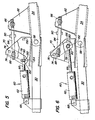
- FIG. 1 shows a tandem flight with a front main frame and a main frame 22 lying opposite it, which are connected to one another in an articulated manner about an essentially transverse axis and are inclined in their position obliquely to the direction of travel.
- the front main frame 20 has a number of typical plow bodies 26, some of which are omitted for ease of illustration. The same applies to the plow bodies 28 of the rear main frame 22.
- the front main frame 20 is rigidly connected to a pull rod 30 which extends forwards, the rigid connection being intended to be present at least with respect to relative vertical movements.
- the pull rod is supported at its front end by a pull connecting device 32, which comprises a rigid connecting member 34, which connects to the connection member 38 of the tractor 36 connected and supported by this. Since the main frame 20 is inclined with respect to the direction of travel, the front right end 40 lies on the right and in front of the left front end, which is represented by the drawbar.
- the front right end of the main frame 20 is supported by a furrow wheel 42 through a support linkage 44.
- the rear end of the main frame 20 as well as the front end of the rear main frame 22 are supported on the ground by a wheeled bogie 46 while the rear end of the rear frame is typically supported by a further furrow wheel 48 and a feeler wheel 50.
- Figs. 2 and 3 From Figs. 2 and 3 it can be seen that the front end of the rigid member 34 of the train connection 32 is supported on the pull tab 52 of the tractor, namely - with the aid of a vertical pivot pin 56 and a transverse pivot pin 54.
- the pull rod 30 and the rigid member 34 are connected to one another in an articulated manner about a transverse axis 58.
- the front left end of the main frame 20 is raised or lowered by the link 58 when the rigid member 34 and the tie rod 30 are bent up or down.
- a force-exerting device in the form of a double-acting hydraulic motor, in particular a thrust piston motor 60 is used for lifting and lowering about the pivot axis 58.
- motors can also be used.
- the motor used here is particularly easy to control remotely.
- the functions of the hydraulic motor are such that the train connection device 32 is raised when the thrust piston cylinder is started and when Retracting is lowered. It can be seen that the parts can also be connected in the opposite manner to the associated connecting elements, so that exactly opposite relationships result. The following description therefore only serves as an example description.
- the engine 60 includes a cylinder 62, a piston 64 and a piston rod 66 (see FIG. 7).
- the cylinder is articulated at 68 on the pull rod 30 behind the transverse axis 58, while the piston rod extends forward and is connected to the rigid link 34 of the train connection via a force transmission device 70.
- the pull rod carries an upstanding holder 74 directly behind the horizontal pivot pin 58.
- This can be of different designs.
- two vertical plates can be provided, between which an arm 78 can freely pivot forward and backward about a pivot pin 76.
- the arm protrudes from the Zpafen 76. Its lower end is connected to the free end of the piston rod 66 by a connecting device 80 to be described further below.
- Another upright holder 82 is rigidly supported by the rigid member 34 in the direction of travel in front of the pivot axis 58.
- This holder is articulated to a central region between the ends of the arm 80, specifically via a link 84.
- the link 84 is connected to the front holder 82 and the central region of the arm 78 via front and rear threaded regions 86 and 88, respectively. 80 connected.
- the rear link 88 is below the pivot pin 76 when the hydraulic motor 60 is extended and retracted in the manner previously described.
- the threaded connections 86 and 88 allow the effective length between the arm 78 and the front bracket to be varied by means of a section 90 which is rigidly provided on a central region of the link 84.
- Figures 9 through 14 best show details of the linkage, jack, and other parts.
- the furrow impeller includes an axis, not shown, which is rigidly connected to an upright shaft 92 which is pivotable about a vertical axis in a bearing housing 94.
- the front end of the main frame 20 rigidly carries a holder 96.
- the support linkage 44 has two parallel links 98 which are articulated at their opposite ends to the bearing housing 94 or the holder 96 of the main frame.
- a double-acting hydraulic motor in the form of a reciprocating piston engine 100 lies between the bearing housing and the holder 96 and parallel to the supporting linkage, so that a relative lifting and lowering movement can be carried out between the main frame and the furrow impeller.
- this lifting and lowering movement of the main frame is coordinated via the furrow impeller with the corresponding lifting and lowering movement by the train connection 32.
- the hydraulic motor 100 comprises a cylinder 102, a piston 104 (FIG. 8) and a piston rod 106.
- the closed end of the cylinder has an articulated connection 108 with the carrier 94 for the furrow impeller.
- the piston rod extends upwards and backwards to a connection device 110 with the holder 96.
- bistable link As a bistable link, this has an arm 112 which can be pivoted on the holder 96 about a cross pin 114. For simplicity and clarification, it is assumed that the arm moves from front to back and vice versa. However, these terms are only to be understood here relatively and not in a limiting sense.
- the arm extends down substantially. Its free end is connected to the end of the piston rod 106 via a cross pin 116, so that the extension and retraction of the motor swings the arm.
- the pivoting of the arm is limited in angular extent between two positions on opposite sides of a straight line drawn between the cylinder anchor pin 108 and the pivot axis .114 of the arm. Controlled movement of the arm in these two phases is achieved by front and rear stops 118 and 120. These are provided on the arm and can be used with corresponding Front and rear portions or projections 122 and 124 of the holder 96 cooperate in FIG. 12. 9 and 12 show the components in the fully raised transport position of the plow. The furrow impeller motor is extended.
- the arm is pivoted forward into a position in contact with the rear stop. This prevents further counterclockwise pivoting.
- a pin 126 can be inserted through aligned openings (not numbered) in the arm and in the holder to fix the arm in this position. When the pin 126 is not needed, it can be inserted into the opening 128 in a non-use position.
- the plow is lowered to the ground until the associated hydraulic motor allows the arm to pivot past the center position to abut the stop members 120, 124 . Then the pin 126 is in the locking position inserted in the upper openings of the arm and holder.
- the operation of the bistable means may perhaps better in the description of the lowering of the plow, from the position of Figure 12 into the position shown in FIG. -. 13 can be understood.
- the pin 126 is removed from the locked position and inserted into the openings 128.
- the furrow impeller swings essentially around pin 116 until the line through points 108, 116, 114 is reached. This is the dead center line.
- arm 112 snaps beyond the dead center line in the clockwise direction. It is possible to return to the raised position from the work-on position with the arm in the same position.
- the raised position of the plow is at a constant height, regardless of whether it is raised from the plowed position or from the normal working position.
- the bistable device ensures two different relative positions of the furrow wheel.
- the plow In order to change from the plowing position to the normal working position, the plow is brought into a position in which the furrow wheel can enter a furrow. The plow is still lying on the unploughed field, while the furrow wheel is literally hanging in the air. At that moment, the tractor is stopped and the hydraulic motor in question is retracted so that the plow penetrates the ground. If the engine is retracted further, the wheel is raised from the furrow floor. As a result, the arm 112 is pivoted in the counterclockwise direction until the stops 120, 124 take effect (FIG. 14). The pin 126 is inserted into its locked position (upper hole) to make this position normal To maintain the working process. When the tractor is driven forward, the plow bodies step into the ground and the furrow wheel runs in a furrow.
- the two hydraulic motors are connected in series.
- This series connection also includes a device to restore the synchronization of the associated pistons.
- 1 shows a hydraulic control device also for the impeller bogie, the rear furrow impeller and the height sensing wheel, these features are not of particular importance and the description is omitted. Also, for simplicity and clarity, the lines for the two motors are not shown in Fig. 1.
- the tractor comprises a hydraulic system with a pump P, a control valve V and a sump S.
- a line 130 leads to the closed end of the motor 60 for the train connection.
- a series switching line 132 leads from the rod end 60 to the closed end of the hydraulic motor 100 for the furrow impeller.
- a return line goes from the rod end of the motor for the furrow impeller back to the valve and from there to the sump.
- the two lines are reversed for reverse movements. The valve can thus be selectively adjusted so that each engine is pressurized.
- Fig. 7 shows a representative setting device for the rod end of the motor for the train connection. This comprises a main connection 136 and an auxiliary connection or synchronization control connection 138. Reference is also made to FIG. 7A.
- the closed end of the engine is believed to be pressurized with the main port downstream of the auxiliary port. When the piston reaches its extended position, it exposes auxiliary port 138 and allows further pressurization of the closed end of motor 100 in the event that the piston there is out of phase.
- the reverse stroke of the motor assigned to the furrow wheel leads to a complete retracting position of the motor assigned to the train connection.
- the engine 100 also has a main connector 140 and an auxiliary connector 142.
- the piston is at the end of the extended position.
- a pressure difference is applied to the two sides of the piston 64 through the opening 138.
- the problem which arises as a result can be eliminated by a device which removes the extension force on the end 66 on the piston rod side. This device is best seen in FIGS. 5 and 6.
- the connecting device 80 which connects the piston rod end 66 and the force transmission arm 78 to one another.
- a slot 150 in the lower region of the arm is part of this power transmission device.
- this includes a cross pin 152 which projects through the free end of the piston rod and slides in the slot. 5, which shows the lowered position of the plow, when the arm is in the rear position, the slot extends substantially vertically, ie substantially perpendicular to the general direction of travel or direction of movement of the piston rod 66. This makes each Empty connection excluded when the piston rod is extended.
- a lower front section of the arm has an angled region 154 which, after the arm has been pivoted forwardly into the position according to FIG. 6, engages on the stop 156 of the holder 76.
- the pin 152 can thus move freely in the slot, so that the piston 64 covers the auxiliary connection 138, so that the main connection 136 to the front of the piston 64 is fully open.
- the plow when the plow is in the fully raised position, its weight mainly by the front furrow wheel, the bogie and the rear wheels. Weight is usually concentrated along the line of the front and rear beams. Almost the entire plow weight is thus removed from the train connection device 32, ie the train connection device can bump upwards. To a certain extent, the reverse is the case when plowing, ie when the weight shifts more to the connecting device.
Abstract
Bei einem von einem Ackerschlepper nachgeschleppten Pflug ist ein hydraulischer Verstellmotor zur Verstellung der relativen Höhenlage zwischen einem Furchenlaufrad (42) und dem zugehörigen Pflughauptrahmen (20) sowie für die Zugverbindungseinrichtung (32) zwischen dem Hauptrahmen (20) und einem starren Anschlußglied (34) des Akkerschleppers vorgesehen. Eine einfache mechanische bi-stabile Einrichtung (112) dient dazu, um den beiden unterschiedlichen notwendigen Arbeitsstellungen für das Anpflügen, wo das Furchenlaufrad (42) auf der Oberseite des Ackers läuft, und der normalen Arbeitsweise zu verwirklichen, wo das Furchenlaufrad (42) in einer schon vorhandenen Furche läuft. Hierdurch können die beiden hydraulischen Motore (60, 102) für das Furchenlaufrad (42) und für die Zugverbindung (32) auf einfache und leicht zu steuernde Weise hydraulisch in Reihe geschaltet werden, wobei der hydraulische Kreis eine Einrichtung umfaßt, um bei jedem Arbeitszyklus den Gleichlauf der beiden zugehörigen Kolben und Kolbenstangen zu gewährleisten.In a plow towed by a tractor, a hydraulic adjusting motor for adjusting the relative altitude between a furrow wheel (42) and the associated plow main frame (20) and for the train connection device (32) between the main frame (20) and a rigid connecting member (34) of the Battery tractors provided. A simple mechanical bi-stable device (112) serves to realize the two different working positions necessary for plowing where the furrow wheel (42) runs on the top of the field and the normal mode of operation where the furrow wheel (42) in an existing furrow is running. As a result, the two hydraulic motors (60, 102) for the furrow wheel (42) and for the train connection (32) can be hydraulically connected in series in a simple and easy-to-control manner, the hydraulic circuit comprising a device for the each cycle To ensure synchronism of the two associated pistons and piston rods.
Description
Die Erfindung betrifft einen von einem Ackerschlepper nachgeschleppten Pflug mit einem -bevorzugt geneigt zur Fahrtrichtung angeordneten- Hauptrahmen, an einem Stützgestänge abgestützten Furchenlaufrad und einem vertikal verstellbaren Gestänge zum Abstützen des Hauptrahmens an dem Stützgestänge und zum vertikalen Verstellen des Furchenlaufrades gegenüber dem Hauptrahmen zwischen einer normalen Arbeitsstellung und einer Anpflügarbeitsstellung.The invention relates to a plow towed by a tractor with a main frame, preferably inclined to the direction of travel, a furrow wheel supported on a support rod and a vertically adjustable rod for supporting the main frame on the support rod and for vertical adjustment of the furrow wheel relative to the main frame between a normal working position and a cultivation position.
Bei derartigen Pflügen ist es üblich, daß die seitlich im Abstand liegenden vorderen Bereiche des Pfluges über in senkrechter Richtung verstellbare Zugverbindungseinrichtungen am Ackerschlepper und über in vertikaler Richtung verstellbare Verbindungsgestänge mit einem Furchenlaufrad abstützend verbunden sind. Eine solche Anordnung zeigt beispielsweise die US-PS 32 36 313. Zur Verstellung des Furchenlaufrades weist diese bekannte Anordnung ein Stützgestänge auf, dem ein doppelwirkender hydraulischer Motor zugeordnet ist. Das Stützgestänge ist mechanisch mit der Zugverbindungseinrichtung verbunden, so daß eine Betätigung des hydraulischen Motors das Stützgestänge des Furchenlaufrades und die Zugverbindungseinrichtung im wesentlichen gemeinsam betätigt werden, so daß der Pflugrahmen während der Anhub- und Absenkbewegung im wesentlichen die gleiche Raumlage beibchält. Während des Absenkens des Pflugrahmens von einer voll angehobenen Transportstellung in eine Stellung, in der das Feld angep'flügt wird, ist es hierbei möglich, den Rahmen um ein größeres Ausmaß gegenüber dem vorderen Furchenlaufrad abzusenken, als während der normalen Pflugarbeiten, während deren sich das Furchenlaufrad im Grunde einer Furche befindet. Hierzu ist es notwendig, den hydraulischen Motor in zwei Phasen zu steuern, nämlich in einem speziellen Hub zur Erreichung einer Absenkstellung für das Anpflügen und in einem zweiten unterschiedlichen Hub zum Absenken in die normale Arbeitsstellung.With plows of this type, it is common for the laterally spaced front areas of the plow to be connected to a furrow impeller in a supporting manner by means of pulling connection devices on the agricultural tractor which can be adjusted in the vertical direction and by means of connecting rods which can be adjusted in the vertical direction. Such an arrangement is shown, for example, in US Pat. No. 3,236,313. To adjust the furrow impeller, this known arrangement has a support linkage to which a double-acting hydraulic motor is assigned. The support linkage is mechanically connected to the train connection device, so that actuation of the hydraulic motor, the support linkage of the furrow impeller and the train connection device are operated essentially together, so that the plow frame maintains essentially the same spatial position during the lifting and lowering movement. During the lowering of the plow frame from a fully raised transport position to a position in which the field is plowed, it is possible to enlarge the frame by a larger amount compared to the front Lower the furrow wheel than during normal plowing, during which the furrow wheel is basically a furrow. For this it is necessary to control the hydraulic motor in two phases, namely in a special stroke to achieve a lowering position for plowing and in a second different stroke to lower it into the normal working position.
Es ist ferner bei einem nachgezogenen Pflug bekannt, der Zugverbindungseinrichtung selbst einen hydraulischen Motor zum Heben und Senken zuzuordnen. Dieser liegt zwischen der starr mit dem Hauptrahmen des Pfluges verbundenen Zugstange und einem starren Zugglied des Ackerschleppers, um die Gelenkverbindung zwischen diesen beiden Teilen zu heben oder zu senken (vergl. US-PS 33 21 029).It is also known in a trailed plow to associate the train connection device itself with a hydraulic motor for lifting and lowering. This lies between the tie rod rigidly connected to the main frame of the plow and a rigid tie rod of the agricultural tractor in order to raise or lower the articulation between these two parts (see US Pat. No. 3,321,029).
Es ist Aufgabe der Erfindung in einem von einem Ackerschlepper nachgezogenen Pflug die Schwierigkeiten der bekannten Vorrichtungen zu verringern und eine in ihrem Aufbau und der Bedienung besonders einfache Einrichtung zu schaffen, mittels der der Pflugrahmen der Höhe nach unter Beibehaltung der Raumlage verstellt werden kann und dennoch zwei unterschiedliche Stellungen zwischen dem Furchenlaufrad und dem Pflugrahmen einstellen zu können. Die Vereinfachung soll sowohl bezüglich der hydraulischen Mittel als auch bezüglich der mechanischen Gestänge erreicht werden.It is an object of the invention in a plow trailed by a plow to reduce the difficulties of the known devices and to create a particularly simple structure and operation, by means of which the plow frame can be adjusted in height while maintaining the spatial position and still two to be able to set different positions between the furrow wheel and the plow frame. The simplification should be achieved both with regard to the hydraulic means and with regard to the mechanical linkage.
Diese Aufgabe wird erfindungsgemäß dadurch gelöst, daß ein doppelt wirkender hydraulischer Motor zwischen dem Hauptrahmen und dem Stützgestänge für das Furchenlaufrad vorgesehen ist, und daß eine bistabile Verbindungseinrichtung zwischen dem einen Ende des Motors und dem Hauptrahmen angeordnet ist. Dabei ist diese Verbindungseinrichtung so ausgebildet, daß sie um die Höhendifferenz zwischen den beiden Arbeitsstellungen des Furchenlaufrades verstellbar ist. Aufgrund dieser Ausbildung kann gewährleistet werden, daß die beiden hydraulischen Motore für das Stützgestänge des Furchenlaufrades und für die Zugverbindungseinrichtung gleichzeitig und gleichphasige Bewegungen ausführen können, und zwar unabhängig davon, ob das Furchenlaufrad in die normale Arbeitsstellung oder in die Anpflügstellung bewegt werden soll, in der das Furchenlaufrad statt in einer Furche auf der Oberseite des Bodens läuft. Da der Motor für das Furchenlaufrad trotz der unterschiedlichen Stellungen dieses Rades im Vergleich zu dem Hauptrahmen des Pfluges stets gleiche Bewegungshübe ausführen kann, vereinfacht sich die Anordnung bezüglich des Furchenlaufrades ganz entscheidend. Hinzu kommt aber auch, daß die hydraulische Anordnung insgesamt wesentlich vereinfacht werden kann. Dazu ist zweckmäßigerweise als Höhenverstelleinrichtung der Zugverbindungsvorrichtung ebenfalls ein doppelt wirkender hydraulischer Motor vorgesehen, der mit dem hydraulischen Motor des-Stützgestänges des Laufrades zur Ausführung gemeinsamer Hübe hydraulisch in Reihe geschaltet ist, derart, daß der Hauptrahmen bei Höhenverstellungen seine Lage beibehält. Beide hydraulische Stellmotore können also hydraulisch miteinander durch Reihenschaltung gekoppelt sein, so daß sie zwangsweise gleiche Bewegungen ausführen. Dennoch ist es möglich das Furchenlaufrad in die eine oder die andere der beiden Arbeitsstellungen zu bewegen.This object is achieved in that a double-acting hydraulic motor is provided between the main frame and the support linkage for the furrow impeller, and in that a bistable connecting device is arranged between the one end of the motor and the main frame. This connecting device is designed so that it by the height difference is adjustable between the two working positions of the furrow wheel. This design can ensure that the two hydraulic motors for the support linkage of the furrow wheel and for the train connection device can perform simultaneous and in-phase movements, regardless of whether the furrow wheel is to be moved into the normal working position or in the in-planting position in the the furrow wheel runs instead of in a furrow on the top of the ground. Since the motor for the furrow wheel can always carry out the same movement strokes in spite of the different positions of this wheel in comparison to the main frame of the plow, the arrangement with respect to the furrow wheel is decisively simplified. In addition, there is also the fact that the hydraulic arrangement as a whole can be significantly simplified. For this purpose, a double-acting hydraulic motor is also expediently provided as the height adjustment device of the train connection device, which is hydraulically connected in series with the hydraulic motor of the support linkage of the impeller for carrying out common strokes, in such a way that the main frame maintains its position when the height is adjusted. Both hydraulic servomotors can thus be hydraulically coupled to one another by series connection, so that they necessarily perform the same movements. Nevertheless, it is possible to move the furrow wheel to one or the other of the two working positions.
Bevorzugt werden in beiden Fällen hydraulische Schubkolbenmotore verwendet. Hierbei ist es noch besonders günstig, wenn man zwangsweise wirkende Mittel vorsieht, welche dafür sorgen, daß die beiden Motore nicht außer Takt geraten. Dazu kann dem hydraulischen Speisekreis der beiden hydraulischen Motore eine selbsttätig arbeitende Einrichtung zugeordnet sein, welche bei jedem Arbeitszyklus die Gleichlaufphase der beiden Motore automatisch herstellt. Zu diesem Zweck kann vorteilhafterweise bei Verwendung von Schubkolbenmotoren deren kolbenstangenseitigem hydraulischen Leitungsanschluß jeweils ein den Gleichtakt der Bewegungen steuernder Leitungshilfsanschluß zugeordnet sein, und zwar so, daß bei Ausfahren der Kolbenstange durch den zugehörigen Kolben in Abhängigkeit von der Kolbenannäherung an die Ausfahr-Endstellung der Leitungshilfsanschluß zunächst versperrt und dann vom Kolben zur Verbindung beider Kolbenseiten mit dem kolbenstangenseitigen Leitungsanschluß freigelegt wird.Hydraulic thrust piston motors are preferably used in both cases. It is particularly advantageous here to provide means which act in a positive manner and which ensure that the two motors do not get out of step. For this purpose, an automatically operating device can be assigned to the hydraulic feed circuit of the two hydraulic motors, which device controls the synchronous phase of the two motors in each working cycle automatically creates. For this purpose, when using thrust piston motors, their hydraulic line connection on the piston rod side can each be assigned a line auxiliary connection controlling the common mode of the movements, in such a way that when the piston rod is extended by the associated piston depending on the piston approach to the extended end position of the line auxiliary connection blocked and then exposed by the piston to connect both sides of the piston with the piston rod-side line connection.
Um bei der Einzugbewegung ein Verschließen des Leitüngshilfsanschlusses zu ermöglichen, ist zweckmäßigerweise der der Zugverbindung zugeordnete Schubkolbenmotor an seinem Kolbenstangenende mit der Zugverbindung über eine Einrichtung verbunden, welche bei Einfahren des zugehörigen Kolbens einen begrenzten, aber zum erneuten Versperren des Leitungshilfsanschlusses ausreichende Einschubbewegung des Kolbens bewirkt. Die bistabile Verbindungseinrichtung zwischen dem Schubkolbenmotor und dem Hauptrahmen weist vorzugsweise eine beiderseits ihrer Mittelstellung stabile.Vorrichtung auf, die in Abhängigkeit von der Einziehbewegung des Motors automatisch in ihre eine stabile Stellung verschwenkbar ist, wenn das Furchenlaufrad sich in der normalen Arbeitsstellung befindet und in ihrer anderen stabilen Stellung, wenn dieses sich in der Anpflüg-Arbeitsstellung befindet. Die beiden stabilen Stellungen der bistabilen Einrichtung lassen sich durch Anschläge für einen der bistabilen Verbindungseinrichtung zugeordneten Arm sicherstellen. Diesem Arm kann außerdem noch eine Verriegelungseinrichtung zugeordnet sein, mittels der dieser Arm in der normalen Arbeitsstellung verriegelbar ist, so daß die automatische Umstellung nur bei Beginn des Pflügens wirksam ist.In order to enable the auxiliary guide connection to be closed during the pull-in movement, the thrust piston motor assigned to the train connection is expediently connected at its piston rod end to the train connection via a device which, when the associated piston is retracted, causes a limited push-in movement of the piston which is sufficient to block the auxiliary line connection again. The bistable connecting device between the thrust piston motor and the main frame preferably has a device which is stable on both sides of its central position and which, depending on the retracting movement of the motor, can automatically be pivoted into its stable position when the furrow wheel is in the normal working position and in its other position stable position when it is in the work-on position. The two stable positions of the bistable device can be ensured by stops for an arm assigned to the bistable connecting device. This arm can also be assigned a locking device by means of which this arm can be locked in the normal working position, so that the automatic changeover is effective only when plowing begins.
Die Erfindung wird nachfolgend anhand schematischer Zeichnungen an einem Ausführungsbeispiel näher erläutert.The invention is explained in more detail below with the aid of schematic drawings using an exemplary embodiment.
Es zeigen:
- Fig. 1 eine Draufsicht auf einen Pflug gemäß der Erfindung.
- Fig. 2 im Ausschnitt und im größeren Maßstabe in Draufsicht die Zugverbindungseinrichtung.
- Fig. 3 die Anordnung nach Fig. 2 in Seitenansicht.
- Fig. 4 in größerem Maßstabe und perspektivischer Ansicht die Stützvorrichtung für das Furchenlaufrad und den zugehörigen Stellmotor.
- Fig. 5 eine Seitenansicht ähnlich der Fig. 3, jedoch in größerem Maßstabe der Zugverbindungseinrichtung in einer Stellung.
- Fig. 6 in gleicher Darstellung wie Fig. 5 die Zugverbindungseinrichtung in einer zweiten Stellung.
- Fig. 7 in größerem Maßstabe einen Teilschnitt durch den Stellmotor der Zugverbindungseinrichtung.
- Fig. 7A eine Draufsicht entlang der Blickrichtung 7A-7A der Fig. 7.
- Fig. 8 eine schematische hydraulische Schaltung für den hydraulischen Speisekreis der beiden hydraulischen Motore.
- Fig. 9 in vereinfachter Darstellung und verkleinertem Maßstabe die Beziehung zwischen dem Pflugrahmen und dem Furchenlaufrad bei Transportstellung.
- Fig. 10 in gleicher Darstellung wie Fig. 9 die Beziehung beim Anpflügen.
- Fig. 11 in ähnlicher Darstellung wie Fig. 10 die relative Beziehung bei der normalen Arbeitsstellung.
- Fig. 12 eine schematische Darstellung des Stützgestänges und des hydraulischen Motors zum Verstellen des Furchenlaufrades in der Transportstellung.
- Fig. 13 in ähnlicher Darstellung wie Fig. 12 die relative Lage der Teile in der Anpflügstellung und
- Fig. 14 in ähnlicher Darstellung wie Fig. 12 und 13 die relative Lage der Teile in der normalen Arbeitsstellung.
- Fig. 1 is a plan view of a plow according to the invention.
- Fig. 2 in detail and on a larger scale in plan view of the train connection device.
- Fig. 3 shows the arrangement of FIG. 2 in side view.
- Fig. 4 in a larger scale and perspective view, the support device for the furrow impeller and the associated servomotor.
- Fig. 5 is a side view similar to Fig. 3, but on a larger scale of the train connection device in one position.
- Fig. 6 in the same representation as Fig. 5, the train connection device in a second position.
- Fig. 7 on a larger scale a partial section through the servomotor of the train connection device.
- 7A shows a plan view along the viewing direction 7A-7A of FIG. 7.
- Fig. 8 is a schematic hydraulic circuit for the hydraulic feed circuit of the two hydraulic motors.
- Fig. 9 in a simplified representation and reduced scale, the relationship between the plow frame and the furrow wheel in the transport position.
- Fig. 10 in the same representation as Fig. 9, the relationship when plowing.
- Fig. 11 in a representation similar to Fig. 10, the relative relationship in the normal working position.
- Fig. 12 is a schematic representation of the support linkage and the hydraulic motor for adjusting the furrow wheel in the transport position.
- Fig. 13 in a similar representation as Fig. 12, the relative position of the parts in the planted position and
- Fig. 14 in a similar representation as Fig. 12 and 13, the relative position of the parts in the normal working position.
Aus Fig. 1 ist ein Tandempflug mit einem vorderen Hauptrahmen und einem gegenüber diesem zurückliegenden Hauptrahmen 22, die um eine im wesentlichen quer verlaufende Achse im Bereich 24 gelenkig miteinander verbunden und in ihrer Lage schräg zur Fahrtrichtung geneigt sind.1 shows a tandem flight with a front main frame and a
Der vordere Hauptrahmen 20 weist eine Reihe von typischen Pflugkörpern 26 auf, von denen einige zur Vereinfachung der Darstellung weggelassen sind. Das gleiche gilt für die Pflugkörper 28 des hinteren Hauptrahmens 22. Der vordere Hauptrahmen 20 ist starr mit einer sich nach vorne erstreckenden Zugstange 30 verbunden, wobei die starre Verbindung zumindestens bezüglich relativer vertikaler Bewegungen vorliegen soll. Die Zugstange wird an ihrem vorderen Ende von einer Zugverbindungseinrichtung 32 unterstützt, die ein starres Verbindungsglied 34 umfaßt, welches mit dem Anschluß- t glied 38 des Ackerschleppers 36 verbunden und von diesem Unterstützt ist. Da der Hauptrahmen 20 gegenüber der Fahrtrichtung geneigt ist, liegt das vordere rechte Ende 40 rechts und vor dem linken vorderen Ende, welches durch die Zugstange repräsentiert wird. Das vordere rechte Ende des Hauptrahmens 20 wird durch ein Furchenlaufrad 42 abgestützt,und zwar über ein Stützgestänge 44. Das zurückliegende Ende des Hauptrahmens 20 ebenso wie das vordere Ende des rückwärtigen Hauptrahmens 22 werden durch ein mit Rädern versehenes Drehgestell 46 am Boden abgestützt, während das rückwärtige Ende des rückwärtigen Rahmens typischerweise von einem weiteren Furchenlaufrad 48 und einem Fühlrad 50 unterstützt ist.The front
Aus den Fig. 2 und 3 geht hervor, daß das vordere Ende des starren Gliedes 34 der Zugverbindung 32 an der Zuglasche 52 des Ackerschleppers abgestützt ist, und zwar - mit Hilfe eines senkrechten Schwenkzapfens 56 und eines quer verlaufenden Schwenkzapfens 54. Die Zugstange 30 und das starre Glied 34 sind um eine Querachse 58 gelenkig miteinander verbunden. Das vordere linke Ende des Hauptrahmens 20 wird angehoben oder abgesenkt vermittels der Gelenkverbindung 58, wenn das starre Glied 34 und die Zugstange 30 nach oben oder unten ausgebuckelt werden. Dies gibt der Zugverbindungseinrichtung die charakteristische Eigenschaft, daß sie in senkrechter Richtung verstellt werden kann. Zum Heben und Senken um die Schwenkachse 58 dient eine kraftausübende Einrichtung in Form eines doppelt wirkenden hydraulischen Motors, insb. eines Schubkolbensmotors 60. Es können aber auch andere geeignete Motoren eingesetzt werden. Der hier beispielsweise verwendete Motor läßt sich besonders leicht fernsteuern. Im vorliegenden Falle sind die Funktionen des hydraulischen Motors derart, daß die Zugverbindungseinrichtung 32 bei Ansfahren des Schubkolbenzylinders angehoben und beim Einziehen abgesenkt wird. Es ist ersichtlich, daß die Teile auch mit den zugehörigen Verbindungselementen in umgekehrter Weise verbunden sein können, so daß sich genau entgegengesetzte Zusammenhänge ergeben. Die nachfolgende Beschreibung dient also nur als Beispielsbeschreibung.From Figs. 2 and 3 it can be seen that the front end of the
Der Motor 60 umfaßt einen Zylinder 62, einen Kolben 64 und eine Kolbenstange 66 (vergl. Fig. 7). Der Zylinder ist bei 68 an der Zugstange 30 hinter der Querachse 58 angelenkt, während die Kolbenstange sich nach vorne erstreckt und über eine Kraftübertragungseinrichtung 70 mit dem starren Glied 34 der Zugverbindung verbunden ist. Zu diesem Zweck trägt die Zugstange unmittelbar hinter dem horizontalen Schwenkzapfen 58 einen aufragenden Halter 74. Dieser kann unterschiedlich ausgebildet sein. Im vorliegenden Beispiel können zwei senkrechte Platten vorgesehen sein, zwischen denen ein Arm 78 frei um einen schwenkzapfen 76 nach vorne und nach hinten schwenken kann. Der Arm ragt von dem Zpafen 76 nach unten. Sein unteres Ende ist mit dem freien Ende der Kolbenstange 66 durch eine noch weiter unten zu beschreibende Verbindungeinrichtung 80 verbunden. Ein weiterer aufrecht stehender Halter 82 wird starr durch das starre Glied 34 in Fahrtrichtung vor der Schwenkachse 58 unterstützt. Dieser Halter ist mit einem mittleren Bereich zwischen den Enden des Armes 80 gelenkig verbunden, und zwar über einen Lenker 84. Der Lenker 84 ist über vordere und rückwärtige Gewindebereiche 86 und 88 jeweils mit dem vorderen Halter 82 bzw. dem mittleren Bereich des Armes 78,80 verbunden. Die hintere Verbindung 88 liegt unterhalb des Schwenkzapfens 76, wenn der hydraulische Motor 60 in der zuvor beschriebenen Weise ausgefahren und eingezogen wird. Die Gewindeverbindungen 86 und 88 ermöglichen die wirksame Länge zwischen dem Arm 78 und dem vorderen Halter mit Hilfe eines Abschnittes 90 zu verändern, der starr auf einem mittleren Bereich des Lenkers 84 vorgesehen ist. Das Ausfahren der Kolbenstange 66 schwingt den Arm 78 nach vorne, um eine nach vorne gerichtete Kraft auf den vorderen Halter 82 auszuüben. Die Folge ist, daß die Zugstange und die Zugverbindungseinrichtung 32 im Bereich des Querzapfens 58 nach oben schwenkt. Das starre Glied 34 kann dabei um seinen Schwenkzapfen.54 gegenüber dem Ackerschlepper nach oben schwingen. Wenn dagegen der Motor 60 eingefahren wird, senkt sich die Zugstange 30 zusammen mit dem starren Glied 34 und der Gelenkverbindung 58 ab. Die Fig. 3 und 5 zeigen die Teile in der abgesenkten Stellung. Fig. 6 zeigt die Teile in der angehobenen Stellung. Die Beschreibung der hydraulischen Arbeitsweise des Motors 60 wird an dieser Stelle, noch ausgesetzt.The
Wie zuvor erwähnt, wird das rechte vordere Ende des Hauptrahmens 20 auf dem Furchenlaufrad 42 mit Hilfe des Stützgestänges 44 abgestützt. Die Fig. 4 und. 9 bis 14 zeigen am besten Einzelheiten der Gestänge, der Hubeinrichtung und der übrigen Teile.As previously mentioned, the right front end of the
Das Furchenlaufrad umfaßt eine nicht gezeigte Achse, die starr mit einer aufrechten Welle 92 verbunden ist, die um eine senkrechte Achse in einem Lagergehäuse 94 schwenkbar ist. Das vordere Ende des Hauptrahmens 20 trägt starr einen Halter 96. Das Stützgestänge 44 weist im dargestellten Beispiel zwei parallele Lenker 98 auf, die mit ihren entgegengesetzten Enden jeweils an dem Lagergehäuse 94 bzw. dem Halter 96 des Hauptrahmens angelenkt sind. Ein doppelt wirkender hydraulischer Motor in Form eines Hubkolbenmotors 100 liegt zwischen dem Lagergehäuse und dem Halter 96 und parallel zu dem Stützgestänge, so daß eine relative Hubbewegung und Senkbewegung zwischen Hauptrahmen und Furchenlaufrad ausgeführt werden kann. Wie weiter unten gezeigt wird, wird diese Hub- und Senkbewegung des Hauptrahmens über das Furchenlaufrad koordiniert mit der entsprechenden Hub- und Senkbewegung durch die Zugverbindung 32.The furrow impeller includes an axis, not shown, which is rigidly connected to an
Der hydraulische Motor 100 umfaßt einen Zylinder 102, einen Kolben 104 (Fig. 8) und eine Kolbenstange 106. Das geschlossene Ende des Zylinders weist eine Gelenkverbindung 108 mit dem Träger 94 für das Furchenlaufrad auf. Die Kolbenstange erstreckt sich nach oben und nach rückwärts zu einer Verbindungseinrichtung 110 mit dem Halter 96. Diese Teile wirken so zusammen, daß der Motor 100 stets die gleiche Hublänge aufweisen kann, unabhängig davon, ob das Furchenlaufrad sich in der normalen Arbeitsstellung oder in der Anpflügstellung befindet. Im vorliegenden Beispiel wird der Motor 100 ausgefahren, um den Rahmen anzuheben und eingefahren, um ihn abzusenken. Auch hier können die Teile jedoch umgekehrt verbunden sein, so daß auch die umgekehrten Funktionen erreicht werden können.The
Die Mittel, mit denen das genannte Ergebnis erzielt wird, umfassen eine bistabile Einrichtung. Diese weist als bistabiles Glied einen Arm 112 auf, der an dem Halter 96 um einen Querzapfen 114 schwenkbar ist. Zur Vereinfachung und Verdeutlichung wird angenommen, daß der Arm sich von vorne nach hinten und umgekehrt bewegt. Diese Ausdrücke sind hier jedoch nur relativ zu verstehen und nicht im begrenzenden Sinne.The means by which the said result is achieved comprise a bistable device. As a bistable link, this has an
Der Arm erstreckt sich im wesentlichen nach unten. Sein freies Ende ist mit dem Ende der-Kolbenstange 106 über einen Querzapfen 116 verbunden, so daß das Ausfahren und Einfahren des Motors den Arm-verschwenkt. Das Verschwenken des Armes wird bezüglich des Winkelausmaßes zwischen zwei Stellungen auf entgegengesetzten Seiten einer geraden Linie begrenzt, die zwischen dem Zylinderverankerungsstift 108 und der Schwenkachse .114 des Armes gezogen wird. Eine kontrollierte Bewegung des Armes in diesen beiden Phasen wird erreicht durch vordere und rückwärtige Anschläge 118 und 120. Diese sind an dem Arm vorgesehen und können mit entsprechenden vorderen und rückwärtigen Abschnitten oder Vorsprüngen 122 und 124 des Halters 96 nach Fig. 12 zusammenwirken. Die Fig. 9 und 12 zeigen die Komponenten in der voll angehobenen Transportstellung des Pfluges. Der Motor für das Furchenlaufrad ist ausgefahren. Der Arm ist nach vorne in eine Stellung in Anlage an dem rückwärtigen Anschlag verschwenkt. Dadurch wird eine weitere Verschwenkung im Gegenuhrzeigersinne verhindert. Ein Stift 126 kann durch in Fluchtung stehende Öffnungen (nicht mit Bezugszeichen versehen) in dem Arm und in dem Halter gesteckt werden, um den Arm in dieser Stellung festzulegen. Wenn der Stift 126 nicht benötigt wird, kann er in einer Nichtgebrauchsstellung in die Öffnung 128 eingesetzt werden.The arm extends down substantially. Its free end is connected to the end of the
Wenn der Pflug in die normale Arbeitsstellung nach Fig. 11 und 14 abgesenkt werden soll, und wenn angenommen wird, daß das Furchenlaufrad 42 in einer Furche läuft, wird der Stift 126 an Ort und Stelle belassen und der Motor 100 eingefahren. Wenn jedoch eine Furche nicht vorhanden ist, wie dies beim Anpflügen eines Ackers der Fall ist, wird der Stift 126 herausgenommen und der Motor zurückgezogen. Da der Pflug um ein größeres Ausmaß gegenüber dem Furchenlaufrad abgesenkt werden muß, wenn sich das Furchenlaufrad nicht in einer Furche befindet, kann der Arm über seine Mittelstellung umschlagen, bis die Anschlagselemente 118 und 122 zur gegenseitigen Anlage kommen (Fig. 13). Dies liegt daran, daß das Furchenlaufrad auf der Oberseite des Ackers läuft und sich damit in einer höheren Stellung befindet als beim Laufen in einer Furche. Wenn es umgekehrt wünschenswert ist, den Arm 112 in die Stellung für das normale Pflügen zu bewegen, wird der Pflug bis auf der Boden abgesenkt, bis der zugehörige hydraulische Motor ein über die Mittelstellung Hinausschwenken des Armes bis zur Anlage an die Anschlagselemente 120, 124 ermöglicht. Danach wird der Stift 126 in die Riegelstellung in den oberen Öffnungen von Arm und Halter eingesetzt.When the plow is to be lowered to the normal working position shown in FIGS. 11 and 14 and assuming that the
Die Wirkungsweise der bistabilen Einrichtung kann vielleicht besser bei der Beschreibung der Absenkung des Pfluges aus der Stellung nach Fig. 12 in die Stellung nach Fig-. 13 verstanden werden. Zunächst wird der Stift 126 aus der Verriegelungsstellung genommen und in die Öffnunge 128 eingesetzt. Wenn der zugehörige Arbeitsmotor eingefahren wird, erfolgt das Schwenken des Furchenlaufrades im wesentlichen um den Stift 116, bis die Linie durch die Punkte 108, 116, 114 erreicht wird. Dies ist die Totpunktlinie. Da die relative Bewegung zwischen dem Pflugrahmen und dem Furchenlaufrad fortgesetzt wird, schnappt der Arm 112 über die Totpunktlinie im Urzeigersinne hinaus. Eine Rückkehr zu der angehobenen Stellung von der Anpflüg-arbeitsstellung ist bei unveränderter Stellung des Armes möglich. In jedem Fall ist die angehobene Stellung des Pfluges bei einer konstanten Höhe unabhängig davon, ob er aus der Anpflügstellung oder aus der normalen Arbeitsstellung aus angehoben wird. Die bistabile Einrichtung sorgt für zwei unterschiedliche relative Stellungen des Furchenlaufrades.The operation of the bistable means may perhaps better in the description of the lowering of the plow, from the position of Figure 12 into the position shown in FIG. -. 13 can be understood. First, the
Um überzugehen von der Anpflügstellung in die normale Arbeitsstellung wird der Pflug in eine Stellung gebracht, in der das Furchenlaufrad in eine Furche eintreten kann. Der Pflug liegt dabei noch auf dem ungepflügten Acker auf, während das Furchenlaufrad buchstäblich in der Luft hängt. In diesem Augenblick wird der Ackerschlepper angehalten und der betreffende hydraulische Motor eingefahren, so daß der Pflug in den Boden eindringt. Ein weiteres Einfahren des Motors führt zum Anheben des Rades vom Furchenboden. Dadurch wird der Arm 112 im Gegenuhrzeigerinne verschwenkt, bis die Anschläge 120, 124 wirksam werden (Fig. 14). Der Stift 126 wird in seine Verriegelungsstellung (oberes Loch) eingesetzt, um diese Stellung für den normalen Arbeitsvorgang aufrecht zu erhalten. Wenn der Ackerschlepper vorwärts gefahren wird, treten die Pflugkörper in den Boden und das Furchenlaufrad läuft in einer Furche.In order to change from the plowing position to the normal working position, the plow is brought into a position in which the furrow wheel can enter a furrow. The plow is still lying on the unploughed field, while the furrow wheel is literally hanging in the air. At that moment, the tractor is stopped and the hydraulic motor in question is retracted so that the plow penetrates the ground. If the engine is retracted further, the wheel is raised from the furrow floor. As a result, the
Weiter oben ist auf das.Merkmal hingewiesen, wonach die beiden hydraulischen Motore in Reihe geschaltet sind. Diese Reihenschaltung umfaßt weiterhin eine Einrichtung, um den Gleichlauf der zugehörigen Kolben wieder herzustellen. Obwohl Fig. 1 eine hydraulische Steuereinrichtung auch für das Laufraddrehgestell, das hintere Furchenlaufrad und das Höhenfühlrad zeigt, sind diese Merkmale nicht von besonderer Bedeutung und es wird von der Beschreibung Abstand genommen. Auch sind zur Vereinfachung und Deutlichkeit die Leitungen für die beiden Motore in Fig. 1 nicht eingezeichnet.Further up is on that . Feature noted that the two hydraulic motors are connected in series. This series connection also includes a device to restore the synchronization of the associated pistons. 1 shows a hydraulic control device also for the impeller bogie, the rear furrow impeller and the height sensing wheel, these features are not of particular importance and the description is omitted. Also, for simplicity and clarity, the lines for the two motors are not shown in Fig. 1.
Nachfolgend wird bezug genommen auf die Figuren 7, 7A und 8, welche den grundlegenden hydraulischen Schaltkreis zeigen.Reference is now made to Figures 7, 7A and 8 which show the basic hydraulic circuit.
Wie Fig. 8 zeigt umfaßt der Ackerschlepper ein hydraulisches System mit einer Pumpe P, einem Steuerventil V und einem Sumpf S. In einer aktiven Stellung des Ventils führt eine Leitung 130 zu dem geschlossenen Ende des Motors 60 für die Zugverbindung. Eine Reihenschaltleitung 132 führt vom stangenseitigen Ende 60 zu dem geschlossenen Ende des Hydraulikmotors 100 für das Furchenlaufrad. Eine Rücklaufleitung geht vom stangenseitigen Ende des Motors für das Furchenlaufrad zurück zum Ventil und von dort zum Sumpf. In einer anderen aktiven Stellung des Ventils sind die beiden Leitungen für umgekehrte Bewegungen vertauscht. Das Ventil kann also selektiv so eingestellt werden, daß jeder Motor unter Druck gesetzt wird.As shown in Fig. 8, the tractor comprises a hydraulic system with a pump P, a control valve V and a sump S. In an active position of the valve, a
Damit die in Reihe geschalteten Motoren akkurat und wirk-z sam arbeiten umfaßt das hydraulische System Mittel, um die Kolben in Gleichlauf zu bringen. Fig. 7 zeigt eine repräsentative Einstelleinrichtung für das stangenseitige Ende des Motors für die Zugverbindung. Diese umfaßt einen Hauptanschluß136 und einen Hilfsanschluß oder Gleichlaufsteuerungsanschluß 138. Es wird hierzu auch auf Fig. 7A verwiesen. Es wird angenommen, daß das geschlossene Ende des Motors unter Druck steht, wobei sich der Hauptanschluß stromabwärts von dem Hilfsanschluß befindet. Wenn der Kolben seine ausgefahrene Stellung erreicht deckt er den Hilfsanschluß 138 auf und gestattet eine weitere Unterdrucksetzung des geschlossenen Endes des Motors 100 für den Fall, daß der dortige Kolben sich nicht in Phase befindet. Der Rückwärtshub des dem Furchenlaufrad zugeordneten Motors führt zu einer vollständigen Einfahrstellung des der Zugverbindung zugeordneten Motors. Der Motor 100 weist ebenfalls einen Hauptanschluß 140 und einen Hilfsanschluß 142 auf.In order for the motors connected in series to work accurately and effectively, the hydraulic system includes means for synchronizing the pistons. Fig. 7 shows a representative setting device for the rod end of the motor for the train connection. This comprises a
Wie oben vermerkt und in Fig. 7 gezeigt, befindet sich der Kolben am Ende der ausgefahrenen Stellung. Wenn Druck an das kolbenseitige Ende des Motors für die Zugverbindung geleitet wird, so daß dieser einfährt, wird durch die Öffnung 138 eine Druckdifferenz auf die beiden Seiten des Kolbens 64 angelegt. Dadurch wird eine nach innen gerichtete Kraft an dem Kolben 64 erzeugt, die kleiner ist als die nach außen gerichtete Kraft an der Kolbenstange 66. Das Fluid kann durch die Hilfsöffnung entweichen und der Kolben 64 wird nicht zurückgezogen. Das hierdurch.auftretende Problem kann durch eine Einrichtung beseitigt werden, welche die Ausfahrkraft auf das kolbenstangenseitige Ende 66 wegnimmt. Diese Einrichtung ist am Besten aus den Fig. 5 und 6 ersichtlich.As noted above and shown in Fig. 7, the piston is at the end of the extended position. When pressure is applied to the piston side end of the motor for the train connection so that it retracts, a pressure difference is applied to the two sides of the
Es wurde früher schon bezug genommen auf die Verbindungsvorrichtung 80, welche das Kolbenstangenende 66 und den Kraftübertragungsarm 78 miteinander verbindet. Teil dieser Kraftübertragungseinrichtung ist ein Schlitz 150 im unteren Bereich des Armes. Weiterhin gehört hierzu ein Querstift 152, der durch das freie Ende der Kolbenstange ragt und in dem Schlitz gleitet. Wie aus Fig. 5 hervorgeht, welche die abgesenkte Stellung des Pfluges zeigt, verläuft der Schlitz dann, wenn der Arm sich in der rückwärtigen Stellung befindet, im wesentlichen vertikal, d.h. im wesentlichen senkrecht zur allgemeinen Fahrtrichtung oder Bewegungsrichtung der Kolbenstange 66. Hierdurch wird jede Leerverbindung ausgeschlossen, wenn die Kolbenstange ausgefahren wird. Ein unterer vorderer Abschnitt des Armes weist einen abgewinkelten Bereich 154 auf, der nach dem Verschwenken des Armes nach vorne in die Stellung nach Fig. 6 an dem Anschlag 156 des Halters 76 angreift. Erst am Ende dieses Winkelbewegungsbereiches des Armes 78-- erreicht der Motor der Zugverbindung das Ende seines Ausfahrhubes. Hier deckt der Kolben 64 den Hilfsanschluß 138 nach Fig. 7 auf, so daß das früher erwähnte Problem auftreten könnte. Bei diesem Problem kann der Kolben nicht mehr zurückgezogen werden, solange eine Ausfahrkraft auf das kolbenstangenseitige Ende 66 einwirkt. Wenn jedoch der Arm an dem Anschlag 156 angreift, läuft der Stift152 frei bis in den Mittelbereich des Schlitzes (Fig. 6), welcher schräg nach oben und nach hinten geneigt ist. Dadurch wird jede Ausfahrkraft von dem Stift 152 und der Kolbenstange 66 weggenommen, wenn also das Ventil V betätigt wird, um den Pflug abzusenken, führt der Differenzdruck, wie früher erläutert, dazu, daß der Kolben 64 einfährt. Der Stift 152 kann sich damit in dem Schlitz frei bewegen, so daß der Kolben 64 den Hilfsanschluß 138 abdeckt, so daß der Hauptanschluß 136 zur Frontseite des Kolbens 64 voll geöffnet ist. An dieser Stelle ist es wichtig zu bemerken, daß dann, wenn der Pflug sich in der voll angehobenen Stellung befindet, dessen Gewicht hauptsächlich von dem vorderen Furchenlaufrad, dem Drehgestell und den rückwärtigen Rädern aufgenommen wird. Das Gewicht wird normalerweise entlang der Linie der vorderen und rückwärtigen Träger konzentriert. Damit wird nahezu das gesamte Pfluggewicht von der Zugverbindungseinrichtung 32 abgenommen, d.h., daß die Zugverbindungseinrichtung nach oben ausbuckeln kann. Das Umgekehrte ist bis zu einem gewissen Ausmaß der Fall, wenn gepflügt wird, d.h. wenn das Gewicht sich mehr auf die Verbindungseinrichtung verlagert.Reference has previously been made to the connecting
Es kann angenommen werden, daß die Arbeitsweise der beschriebenen Einrichtung einschließlich der Erfindung aus dem Vorstehenden deutlich werden. Es ist ersichtlich, daß die Arbeitsweise der Motoren für die Zugverbindung und für das Furchenlaufrad im wesentlichen synchron erfolgt, mit dem Ergebnis, daß die vorderen Enden des Pfluges während des Anhebens und Absenkens ihre Raumlage beibehalten. Die Steuereinrichtung für das Furchenlaufrad insb. in Verbindung mit dem bistabilen Arm 112 liefert die notwendige Kompensation bezüglich unterschiedlicher Funktionen beim Absenken in eine Arbeitsstellung, in der bereits eine Furche vorliegt und beim Absenken in die Arbeitsstellung, wenn das Furchenlaufrad auf der Oberseite des Ackers laufen muß, wie dies beim Anpflügen eines Feldes der Fall ist. In jedem Fall ist der Rückwärtshub des zugehörigen Motors für-das Furchenlaufrad der gleiche, wodurch der Aufbau und die Betätigung des Ventils V wesentlich erleichtert werden.It can be assumed that the operation of the device described, including the invention, will become clear from the above. It can be seen that the operation of the motors for the train connection and for the furrow impeller is essentially synchronous, with the result that the front ends of the plow maintain their position during lifting and lowering. The control device for the furrow wheel, in particular in connection with the
Es ist ersichtlich, daß wenn in der vorliegenden Beschreibung im Zusammenhang mit einer bevorzugten .Ausführungsform der Erfindung Ausdrücke wie links und rechts und wie ausfahren und einziehen und dgl. verwendet werden, diese lediglich zur Erläuterung und nicht zur Beschränkung dienen.It will be appreciated that when terms such as left and right and how extend and retract and the like are used in the present specification in connection with a preferred embodiment of the invention, they are used for illustration only and not for limitation.
Claims (14)
Applications Claiming Priority (2)
| Application Number | Priority Date | Filing Date | Title |
|---|---|---|---|
| US275572 | 1981-06-22 | ||
| US06/275,572 US4410047A (en) | 1981-06-22 | 1981-06-22 | Tractor-drawn plow with hitch and furrow wheel hydraulic motors connected in series |
Related Child Applications (2)
| Application Number | Title | Priority Date | Filing Date |
|---|---|---|---|
| EP84115705A Division EP0145027A3 (en) | 1981-06-22 | 1982-06-21 | Tractor-drawn plough |
| EP84115705.0 Division-Into | 1984-12-18 |
Publications (2)
| Publication Number | Publication Date |
|---|---|
| EP0068381A1 true EP0068381A1 (en) | 1983-01-05 |
| EP0068381B1 EP0068381B1 (en) | 1986-09-17 |
Family
ID=23052895
Family Applications (2)
| Application Number | Title | Priority Date | Filing Date |
|---|---|---|---|
| EP82105420A Expired EP0068381B1 (en) | 1981-06-22 | 1982-06-21 | Tractor-drawn plough |
| EP84115705A Withdrawn EP0145027A3 (en) | 1981-06-22 | 1982-06-21 | Tractor-drawn plough |
Family Applications After (1)
| Application Number | Title | Priority Date | Filing Date |
|---|---|---|---|
| EP84115705A Withdrawn EP0145027A3 (en) | 1981-06-22 | 1982-06-21 | Tractor-drawn plough |
Country Status (9)
| Country | Link |
|---|---|
| US (1) | US4410047A (en) |
| EP (2) | EP0068381B1 (en) |
| AU (1) | AU542833B2 (en) |
| CA (1) | CA1184806A (en) |
| DE (1) | DE3273320D1 (en) |
| DK (1) | DK280082A (en) |
| ES (1) | ES513294A0 (en) |
| FI (1) | FI822125L (en) |
| ZA (1) | ZA824365B (en) |
Cited By (3)
| Publication number | Priority date | Publication date | Assignee | Title |
|---|---|---|---|---|
| EP0135180A2 (en) * | 1983-09-16 | 1985-03-27 | Deere & Company | Tool carrier with at least one lateral frame |
| DE3511099A1 (en) * | 1985-03-27 | 1986-10-09 | Claas Saulgau GmbH, 7968 Saulgau | AGRICULTURAL MACHINE TO BE ATTACHED TO A TRACTOR |
| EP0807373A1 (en) * | 1996-05-15 | 1997-11-19 | Agco SA | Control of a semi-mounted plough |
Families Citing this family (2)
| Publication number | Priority date | Publication date | Assignee | Title |
|---|---|---|---|---|
| AUPQ221099A0 (en) * | 1999-08-13 | 1999-09-02 | Tanusi Pty Ltd | Improvements to agricultural implements |
| DE102010019819B4 (en) * | 2010-05-08 | 2014-09-18 | Lemken Gmbh & Co. Kg | Semi-Mounted |
Citations (5)
| Publication number | Priority date | Publication date | Assignee | Title |
|---|---|---|---|---|
| US1926401A (en) * | 1929-12-12 | 1933-09-12 | Deere & Co | Plow |
| US3236313A (en) * | 1964-05-28 | 1966-02-22 | Deere & Co | Towed plow |
| US3321029A (en) * | 1964-09-10 | 1967-05-23 | Int Harvester Co | Hydraulically controlled plow |
| US3481407A (en) * | 1966-09-15 | 1969-12-02 | Deere & Co | Plow |
| US3731749A (en) * | 1971-02-23 | 1973-05-08 | Deere & Co | Towed plow |
Family Cites Families (5)
| Publication number | Priority date | Publication date | Assignee | Title |
|---|---|---|---|---|
| US2605686A (en) * | 1946-10-28 | 1952-08-05 | John Deere Van Brunt Co | Power lift |
| US2925871A (en) * | 1956-06-08 | 1960-02-23 | Case Co J I | Synchronized multiple motor hydraulic power lift |
| US3627053A (en) * | 1969-04-28 | 1971-12-14 | Deere & Co | Hydraulic power lift system for tractor and trailing implement |
| US4047575A (en) * | 1976-01-08 | 1977-09-13 | Allis-Chalmers Corporation | Foldup implement with lift arrangement for wing thereof |
| US4121852A (en) * | 1976-09-16 | 1978-10-24 | Quanbeck Sherman H | Releasably retained hinged plow |
-
1981
- 1981-06-22 US US06/275,572 patent/US4410047A/en not_active Expired - Fee Related
-
1982
- 1982-06-10 CA CA000404862A patent/CA1184806A/en not_active Expired
- 1982-06-14 FI FI822125A patent/FI822125L/en not_active Application Discontinuation
- 1982-06-16 AU AU84908/82A patent/AU542833B2/en not_active Ceased
- 1982-06-21 ES ES513294A patent/ES513294A0/en active Granted
- 1982-06-21 DE DE8282105420T patent/DE3273320D1/en not_active Expired
- 1982-06-21 ZA ZA824365A patent/ZA824365B/en unknown
- 1982-06-21 EP EP82105420A patent/EP0068381B1/en not_active Expired
- 1982-06-21 EP EP84115705A patent/EP0145027A3/en not_active Withdrawn
- 1982-06-22 DK DK280082A patent/DK280082A/en not_active Application Discontinuation
Patent Citations (5)
| Publication number | Priority date | Publication date | Assignee | Title |
|---|---|---|---|---|
| US1926401A (en) * | 1929-12-12 | 1933-09-12 | Deere & Co | Plow |
| US3236313A (en) * | 1964-05-28 | 1966-02-22 | Deere & Co | Towed plow |
| US3321029A (en) * | 1964-09-10 | 1967-05-23 | Int Harvester Co | Hydraulically controlled plow |
| US3481407A (en) * | 1966-09-15 | 1969-12-02 | Deere & Co | Plow |
| US3731749A (en) * | 1971-02-23 | 1973-05-08 | Deere & Co | Towed plow |
Cited By (4)
| Publication number | Priority date | Publication date | Assignee | Title |
|---|---|---|---|---|
| EP0135180A2 (en) * | 1983-09-16 | 1985-03-27 | Deere & Company | Tool carrier with at least one lateral frame |
| EP0135180A3 (en) * | 1983-09-16 | 1986-07-16 | Deere & Company | Tool carrier with at least one lateral frame |
| DE3511099A1 (en) * | 1985-03-27 | 1986-10-09 | Claas Saulgau GmbH, 7968 Saulgau | AGRICULTURAL MACHINE TO BE ATTACHED TO A TRACTOR |
| EP0807373A1 (en) * | 1996-05-15 | 1997-11-19 | Agco SA | Control of a semi-mounted plough |
Also Published As
| Publication number | Publication date |
|---|---|
| US4410047A (en) | 1983-10-18 |
| DK280082A (en) | 1982-12-23 |
| FI822125L (en) | 1982-12-23 |
| DE3273320D1 (en) | 1986-10-23 |
| ES8304748A1 (en) | 1983-03-16 |
| EP0145027A3 (en) | 1987-10-07 |
| AU8490882A (en) | 1983-01-06 |
| AU542833B2 (en) | 1985-03-14 |
| CA1184806A (en) | 1985-04-02 |
| EP0145027A2 (en) | 1985-06-19 |
| ES513294A0 (en) | 1983-03-16 |
| FI822125A0 (en) | 1982-06-14 |
| EP0068381B1 (en) | 1986-09-17 |
| ZA824365B (en) | 1984-02-29 |
Similar Documents
| Publication | Publication Date | Title |
|---|---|---|
| EP0182229B1 (en) | Vehicle in particular farm tractor with a linking and coupling device for frontal mounting on a vehicle | |
| DE2948899C2 (en) | Implement attachment device | |
| DE19951840A1 (en) | Interface for coupling work equipment to a work vehicle | |
| DE2737053B2 (en) | Agricultural equipment | |
| DE2838829A1 (en) | MULTI-BLADE SEMI-DETACHED PLOW | |
| DE2922355C3 (en) | Equipment unit consisting of an agricultural tractor with three-point hitch and power lift as well as an attachment | |
| DE2541697A1 (en) | MATERIAL HANDLING DEVICE ATTACHED TO A TRACTOR | |
| DE1915825A1 (en) | Tillage equipment | |
| EP0094072A1 (en) | Soil tilling implement | |
| DE4322263B4 (en) | Method for preparing a work vehicle traveling on a floor surface with a work device for road operation and work device for arrangement on such a work vehicle | |
| EP0068381A1 (en) | Tractor-drawn plough | |
| DE3411161C2 (en) | ||
| EP0211967A1 (en) | Combined implement for soil cultivation in agriculture | |
| DE102011111251B4 (en) | agricultural machine | |
| DE4306145A1 (en) | Appliance combination for the ploughing of useful agricultural areas and for ground reworking and/or ground cultivation | |
| EP3785522A1 (en) | Clearance device, vehicle for clearing wood and method for clearing wood | |
| DE3610865A1 (en) | Implement frame for the attachment, in particular, of agricultural working implements to a tractor or the like | |
| EP3598882B1 (en) | Agricultural cultivation device | |
| DE2820529A1 (en) | Tow coupling for tractor hitch - has hydraulically operated towing jaw with vertical adjustment in guides and lower attachment arms | |
| DE19637536C2 (en) | Integrated combination of a plow and a soil preparation device | |
| DE869272C (en) | Three-point suspension for devices that can be attached to the tractor | |
| DE2718980C2 (en) | Divided frame for an agricultural soil cultivation implement | |
| DE3430071C2 (en) | ||
| DE1222303B (en) | Soil cultivation implement mounted on a tractor | |
| DE2607082A1 (en) | PLOW |
Legal Events
| Date | Code | Title | Description |
|---|---|---|---|
| PUAI | Public reference made under article 153(3) epc to a published international application that has entered the european phase |
Free format text: ORIGINAL CODE: 0009012 |
|
| AK | Designated contracting states |
Designated state(s): DE FR GB SE |
|
| 17P | Request for examination filed |
Effective date: 19830610 |
|
| EL | Fr: translation of claims filed | ||
| GRAA | (expected) grant |
Free format text: ORIGINAL CODE: 0009210 |
|
| AK | Designated contracting states |
Kind code of ref document: B1 Designated state(s): DE FR GB SE |
|
| REF | Corresponds to: |
Ref document number: 3273320 Country of ref document: DE Date of ref document: 19861023 |
|
| ET | Fr: translation filed | ||
| PG25 | Lapsed in a contracting state [announced via postgrant information from national office to epo] |
Ref country code: SE Effective date: 19870622 |
|
| PLBE | No opposition filed within time limit |
Free format text: ORIGINAL CODE: 0009261 |
|
| STAA | Information on the status of an ep patent application or granted ep patent |
Free format text: STATUS: NO OPPOSITION FILED WITHIN TIME LIMIT |
|
| 26N | No opposition filed | ||
| PG25 | Lapsed in a contracting state [announced via postgrant information from national office to epo] |
Ref country code: FR Free format text: LAPSE BECAUSE OF NON-PAYMENT OF DUE FEES Effective date: 19880226 |
|
| PG25 | Lapsed in a contracting state [announced via postgrant information from national office to epo] |
Ref country code: DE Effective date: 19880301 |
|
| GBPC | Gb: european patent ceased through non-payment of renewal fee | ||
| REG | Reference to a national code |
Ref country code: FR Ref legal event code: ST |
|
| PG25 | Lapsed in a contracting state [announced via postgrant information from national office to epo] |
Ref country code: GB Effective date: 19881121 |
|
| EUG | Se: european patent has lapsed |
Ref document number: 82105420.2 Effective date: 19880712 |