EP0068252A2 - Fluid-pressure operated linear-drive mechanism - Google Patents
Fluid-pressure operated linear-drive mechanism Download PDFInfo
- Publication number
- EP0068252A2 EP0068252A2 EP82105158A EP82105158A EP0068252A2 EP 0068252 A2 EP0068252 A2 EP 0068252A2 EP 82105158 A EP82105158 A EP 82105158A EP 82105158 A EP82105158 A EP 82105158A EP 0068252 A2 EP0068252 A2 EP 0068252A2
- Authority
- EP
- European Patent Office
- Prior art keywords
- piston
- drive device
- slide
- pressure medium
- drive unit
- Prior art date
- Legal status (The legal status is an assumption and is not a legal conclusion. Google has not performed a legal analysis and makes no representation as to the accuracy of the status listed.)
- Ceased
Links
- 238000005096 rolling process Methods 0.000 claims description 7
- 238000006073 displacement reaction Methods 0.000 claims description 5
- 239000012528 membrane Substances 0.000 claims description 5
- 238000010276 construction Methods 0.000 description 3
- 238000010586 diagram Methods 0.000 description 2
- 238000004891 communication Methods 0.000 description 1
- 230000008878 coupling Effects 0.000 description 1
- 238000010168 coupling process Methods 0.000 description 1
- 238000005859 coupling reaction Methods 0.000 description 1
- 238000012423 maintenance Methods 0.000 description 1
- 230000001960 triggered effect Effects 0.000 description 1
- 238000012800 visualization Methods 0.000 description 1
- XLYOFNOQVPJJNP-UHFFFAOYSA-N water Substances O XLYOFNOQVPJJNP-UHFFFAOYSA-N 0.000 description 1
Images


Classifications
-
- F—MECHANICAL ENGINEERING; LIGHTING; HEATING; WEAPONS; BLASTING
- F03—MACHINES OR ENGINES FOR LIQUIDS; WIND, SPRING, OR WEIGHT MOTORS; PRODUCING MECHANICAL POWER OR A REACTIVE PROPULSIVE THRUST, NOT OTHERWISE PROVIDED FOR
- F03C—POSITIVE-DISPLACEMENT ENGINES DRIVEN BY LIQUIDS
- F03C1/00—Reciprocating-piston liquid engines
- F03C1/02—Reciprocating-piston liquid engines with multiple-cylinders, characterised by the number or arrangement of cylinders
-
- F—MECHANICAL ENGINEERING; LIGHTING; HEATING; WEAPONS; BLASTING
- F16—ENGINEERING ELEMENTS AND UNITS; GENERAL MEASURES FOR PRODUCING AND MAINTAINING EFFECTIVE FUNCTIONING OF MACHINES OR INSTALLATIONS; THERMAL INSULATION IN GENERAL
- F16H—GEARING
- F16H25/00—Gearings comprising primarily only cams, cam-followers and screw-and-nut mechanisms
- F16H25/02—Gearings comprising primarily only cams, cam-followers and screw-and-nut mechanisms the movements of two or more independently moving members being combined into a single movement
Definitions
- the present invention relates to a pressure medium-operated linear drive device for generating a relative displacement between a sled-shaped drive unit and a curve profile slide bar, the drive unit having a plurality of piston-cylinder systems which can be actuated by the pressure medium and whose pistons are supported on the profile of the slide bar and whose cylinders are each connected to the pressure medium source via control valve means.
- Linear drive devices of this type are known from DE-OS No. 2 359 779 or GB-PS No. 1 398 012.
- the structure and the mode of operation of such linear drive devices are essentially dealt with theoretically without giving any further information on possible, practical embodiments.
- the crotch elements each form self-centering sliding joint drive elements with lever means articulated on the one hand on the piston of the crotch elements and on the other hand on the slide housing.
- piston-cylinder systems are formed from air bellows springs with a piston part or from roll membranes used in the cylinders with a loose piston part, which are supported in series depending on the bottom of the slide housing, with channels the piston-cylinder - Connect the systems to the control valve means, which are also attached to the slide housing.
- Each free piston end then expediently carries a rolling element which interacts with the profile of the slide bar and is connected to one end of a pivoting lever, the other end of which is pivotably attached to the slide housing.
- the slide housing should also be supported by counter rollers on the flat side of the slide bar.
- the pressure medium can be air, water, oil and the like.
- this drive device is suitable for generating high thrust forces with the smallest construction volume, it is used according to the invention as a means for moving gates, hangar gates, sluice gates and the like
- Drive device according to the invention here is a substantial simplification of the construction concept, a large weight saving up to two-thirds of comparatively previous drives and a considerable reduction in costs.
- the drive is suitable for both industrial and private use and can be Use any slope up to vertical.
- the drive device can also be used according to the invention as a trolley, transport carriage, media distributor, etc.
- step elements 1, 2 and 3 in the form of pressure-medium-operated piston-cylinder systems to be described in more detail below are provided on a slide-shaped drive unit 10.
- step elements 1, 2 and 3 are actuated via a conventional rotary slide valve 4 by the pressure medium supplied through line 5 and are supported on a curved profile sliding strip 20.
- the rotation of the rotary valve 4 takes place during the relative movement between the drive unit 10 and the slide bar 20 via one of the thrust bar 20 parallel rack 6, on which a gear 7 of the rotary valve 4 rolls.
- the direction of movement of the movement between the drive unit 10 and the slide bar 20 is determined in a known manner by the opening angle and positions of the rotary valve, the forward and backward movement either by reversing the inlet and outlet openings for the pressure medium or by changing the relative angular position of the rotary valve the slide bar can be done. The latter can also be done by moving the rack 6.
- the rest position of the drive device is shown. Upon displacement of the rack 6 up to the stop 8 or 9 (via the shift lever 11), the step elements are advanced in one or the other direction.
- a similar analog construction can also be provided in an electrical manner by using magnets and rotary switches.
- an electrically operated or controlled embodiment there is also the possibility of replacing the rotary slide and the gear coupling by directly scanning sliding contacts, the contact tracks running parallel to the slide bar 20 and forming a linear collector.
- digital control via perforated tape or parallel control via remote display signals or the like is possible.
- FIG. 2 shows a schematic illustration of control rollers 101, 102 and 103, with which the mentioned step elements 1, 2 and 3 are supported on the profiled side 21 of the slide bar 20, with counter or support rollers 12 and 13 on the flat side for a practical embodiment 22 of the slide bar 20 roll.
- the division of the slide bar 20 and the slope of the profile 21 is variable and designed so that in each functional phase or relative position between the drive unit 10 and the slide bar 20, one of the rollers mentioned is located on a flank of the slide bar profile, so that a relative displacement between the drive unit 10 and the slide bar 20 can be triggered both in one direction and in the other.
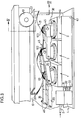
- FIGS. 3 and 4. 3 the front-side wall plate 41 (FIG. 4) for better visualization of the crotch elements 1, 2 and 3 and the associated pivot lever 35 of the pushrod drive are omitted.
- the sled-shaped drive unit with its sled housing 10 is arranged in a stationary manner on a wall 42, a frame or the like, is usually screwed on and is used here for the back and forth movement of a gate 100 or the like, on which object the curve profile Push bar 20 is fixedly arranged via an angle arm 47 (Fig.4).
- the objects to be moved are of course usually guided in displacement frames or the like.
- each piston-cylinder system 1, 2 and 3 is supported on the bottom of the slide housing 10, arranged in series, their cylinder parts being combined in a block 43.
- a so-called rolling membrane is then inserted into each of the cylinder bores, which are not visible here, and clamped with the cover part 44.
- Roll membranes and their functions are known per se and need not be described in more detail here.
- the respective piston part 30 sits on these rolling membranes with a large radial clearance and protrudes from the block 43 with its free, fork-shaped end.
- each piston-cylinder system 1, 2 and 3 is in flow communication with the rotary slide valve 4 via a line 31, 32 and 33 assigned to it, the pinion (not shown here) in the rack 6 (FIG. 4) parallel to the Push bar 20 engages in the manner described.
- each piston-cylinder system 1, 2 and 3 is suitable for absorbing and compensating for any shear force that deviates from the stroke direction, whereby for self-centering of the systems a pivot lever 35 or pairs of pivot levers or a fork-shaped pivot lever at the free end of the Piston 30 attacks and is articulated there via axes 45.
- pairs of swivel levers are provided, the other ends of which are articulated via bolts 46 on the side plates of the slide housing 10.
- a roller 101, 102 or 103 is also freely rotatable on the axis 45 in the fork-shaped end of the piston 30 in question, which rollers are supported on the cam track 21 of the slide bar 20. Then pairs of rollers 13 are used for counter-guidance, which are rotatably mounted on the slide housing 10 and which roll on the flat side 22 of the slide bar 20.
Abstract
Die druckmediumbetriebene Linear-Antriebsvorrichtung umfaßt eine schlittenförmige Antriebseinheit (10), welche sich an einer Kurvenprofil-Schubleiste (20) abstützt. Die Antriebseinheit (10) umfaßt Schrittelemente (1, 2, 3) in Form von Kolben-Zylinder-Systemen, welche über einen Drehschieber (4) von einem Druckmittel angesteuert werden zur Erzeugung einer Relativbewegung zwischen Antriebseinheit (10) und Schubleiste (20). Die Schrittelemente (1, 2, 3) bilden dabei je mit einerseits an den Kolben (30) der Schrittelemente, andererseits am Gehäuse (10) der Antriebseinheit angelenkten Hebelmitteln (35) sich selbst zentrierende Schubgelenkantriebselememte. Dies ermöglicht erstmals eine praktische Ausführungsform einer solchen Vorrichtung.The pressure medium-operated linear drive device comprises a slide-shaped drive unit (10), which is supported on a curve profile sliding bar (20). The drive unit (10) comprises step elements (1, 2, 3) in the form of piston-cylinder systems which are actuated by a pressure medium via a rotary valve (4) to generate a relative movement between the drive unit (10) and the slide bar (20). The step elements (1, 2, 3) each form self-centering sliding joint drive elements with lever means (35) articulated on the one hand on the piston (30) of the step elements, on the other hand on the housing (10) of the drive unit. This enables a practical embodiment of such a device for the first time.
Description
Die vorliegende Erfindung betrifft eine druckmediumbetriebene Linear-Antriebsvorrichtung zur Erzeugung einer Relativverschiebung zwischen einer schlittenförmigen Antriebseinheit und einer Kurvenprofil-Schubleiste, wobei die Antriebseinheit eine Mehrzahl vom Druckmedium betätigbare, Schrittelemente bildende Kolben-Zylinder-Systeme aufweist, deren Kolben sich am Profil der Schubleiste abstützen und deren Zylinder je über Steuerventilmittel mit der Druckmediumsquelle verbunden sind.The present invention relates to a pressure medium-operated linear drive device for generating a relative displacement between a sled-shaped drive unit and a curve profile slide bar, the drive unit having a plurality of piston-cylinder systems which can be actuated by the pressure medium and whose pistons are supported on the profile of the slide bar and whose cylinders are each connected to the pressure medium source via control valve means.
Linear-Antriebsvorrichtungen dieser Art sind durch die DE-OS Nr. 2 359 779 oder die GB-PS Nr. 1 398 012 bekannt geworden. In diesen Schriften wird der Aufbau und die Funktionsweise solcher Linear-Antriebsvorrichtungen im wesentlichen theoretisch abgehandelt ohne nähere Hinweise auf mögliche, praktikable Ausführungsformen zu geben. Beispielsweise wird in diesen Schriften vorgeschlagen, Kolben-Zylinder-Systeme üblicher Bauart zu verwenden, was infolge der Wirksamkeit hoher Querkräfte praktisch kaum durchführbar sein dürfte. Ebensowenig ist in diesen Schriften aber auch der Anwendungsbereich solcher Linear-Antriebsvorrichtungen erkannt worden,sind diese doch in diesen Schriften auf den Antrieb von Werkzeugmaschinenschlitten beschränkt.Linear drive devices of this type are known from DE-OS No. 2 359 779 or GB-PS No. 1 398 012. In these documents, the structure and the mode of operation of such linear drive devices are essentially dealt with theoretically without giving any further information on possible, practical embodiments. For example, it is proposed in these documents to use piston-cylinder systems of a conventional type, which, owing to the effectiveness of high transverse forces, should hardly be practicable. Just as little has the scope of such linear drive devices been recognized in these documents, since in these documents they are limited to the drive of machine tool slides.
Es ist somit Aufgabe der vorliegenden Erfindung eine druckmediumbetriebene Linear-Antriebsvorrichtung zu schaffen, welche allen praktischen Anforderungen gerecht werden kann und welche ein breites Anwendungsspektrum erlaubt.It is therefore an object of the present invention to provide a linear drive device operated by pressure medium, which can meet all practical requirements and which allows a wide range of applications.
Dies wird nun erfindungsgemäss dadurch erreicht, dass die Schrittelemente je mit einerseits an den Kolben der Schrittelemente, andererseits am Schlittengehäuse angelenkten Hebelmitteln sich selbst zentrierende Schubgelenkantriebselemente bilden.This is now achieved according to the invention in that the crotch elements each form self-centering sliding joint drive elements with lever means articulated on the one hand on the piston of the crotch elements and on the other hand on the slide housing.
Hierbei ist es vorteilhaft, wenn die Kolben-Zylinder-Systeme aus Luftbalgfedern mit einem Kolbenteil oder aus in den Zylindern eingesetzte Roll-Membranen mit lose aufgelegtem Kolbenteil gebildet sind, die sich in Reihe je am Boden des Schlittengehäuses abstützen, wobei Kanäle die Kolben-Zylinder-Systeme mit den ebenfalls am Schlittengehäuse befestigten Steuerventilmitteln verbinden.It is advantageous if the piston-cylinder systems are formed from air bellows springs with a piston part or from roll membranes used in the cylinders with a loose piston part, which are supported in series depending on the bottom of the slide housing, with channels the piston-cylinder - Connect the systems to the control valve means, which are also attached to the slide housing.
Zweckmässig trägt dann jedes freie Kolbenende ein mit dem Profil der Schubleiste zusammenwirkendes Abwälzglied und ist mit dem einen Ende eines Schwenkhebels verbunden, dessen anderes Ende schwenkbar am Schlittengehäuse befestigt ist.Each free piston end then expediently carries a rolling element which interacts with the profile of the slide bar and is connected to one end of a pivoting lever, the other end of which is pivotably attached to the slide housing.
Weiter sollte sich das Schlittengehäuse über Gegenrollen auf der Flachseite der Schubleiste abstützen.The slide housing should also be supported by counter rollers on the flat side of the slide bar.
Diese erfindungsgemässen Massnahmen gestatten nun eine kompakte und relativ einfache Linear-Antriebsvorrichtung, die durch die besondere erfindungsgemässe Ausgestaltung der Kolben-Zylinder-Systeme als Schubgelenkantriebselemente geeignet ist, sämtliche auftretenden Querkräfte behinderungsfrei aufzunehmen mit optimalster Schubkrafterzeugung bei geringstem Druckbedarf. Hierbei kann das Druckmedium Luft, Wasser, Oel und dgl. sein.These measures according to the invention now allow a compact and relatively simple linear drive device which, due to the special design of the piston-cylinder systems according to the invention, is suitable as a push-joint drive elements for absorbing all the transverse forces that occur without hindrance, with optimum thrust force generation with the lowest pressure requirement. The pressure medium can be air, water, oil and the like.
Da diese Antriebsvorrichtung geeignet ist, bei kleinstem Bauvolumen hohe Schubkräfte zu erzeugen, wird diese erfindungsgemäss verwendet als Mittel zur Bewegung von Toren, Hangar-Toren, Schleusen-Schiebern und dgl. Vergleichsweise der bisher für diese Anwendungsbereiche installierten Elektromotoren mit Kettenantrieben und dgl. gestattet die erfindungsgemässe Antriebsvorrichtung hier eine wesentliche Vereinfachung der Baukonzeption, eine grosse Gewichtseinsparung bis zu Zweidritteln vergleichsweise bisheriger Antriebe sowie eine erhebliche Kostensenkung. Der Antrieb ist dabei sowohl industriell als auch für Private geeignet und lässt sich in jeder Neigung bis vertikal verwenden.Since this drive device is suitable for generating high thrust forces with the smallest construction volume, it is used according to the invention as a means for moving gates, hangar gates, sluice gates and the like Drive device according to the invention here is a substantial simplification of the construction concept, a large weight saving up to two-thirds of comparatively previous drives and a considerable reduction in costs. The drive is suitable for both industrial and private use and can be Use any slope up to vertical.
In der Bewegungsumkehr kann die Antriebsvorrichtung erfindungsgemäss aber auch als Laufkatze, Transportschlitten, Medienverteiler usw. verwendet werden.In the reversal of motion, the drive device can also be used according to the invention as a trolley, transport carriage, media distributor, etc.
Eine beispielsweise Ausführungsform des Erfindungsgegenstandes soll nachfolgend anhand der Zeichnung näher erläutert werden. Es zeigen:
- Fig. 1 eine Prinzipdarstellung der erfindungsgemässen druckmediumbetriebenen Linear-Antriebsvorrichtung;
- Fig. lA eine Ausführungsvariante gemäss Fig.l;
- Fig. 2 eine Prinzipdarstellung zur Erläuterung der Erzeugung der Linearbewegung;
- Fig. 3 ein praktisches Ausführungsbeispiel, in Seitenansicht, und
- Fig. 4 ein Schnitt entlang der Schnittlinie IV - IV in Fig.3 in grösserem Massstab.
- 1 shows a schematic diagram of the linear drive device operated by the pressure medium according to the invention;
- FIG. 1A shows an embodiment variant according to FIG. 1;
- Fig. 2 is a schematic diagram for explaining the generation of the linear movement;
- Fig. 3 shows a practical embodiment, in side view, and
- Fig. 4 is a section along the section line IV - IV in Figure 3 on a larger scale.
Anhand der Figuren 1 und 2 soll zunächst das Funktionsprinzip der erfindungsgemässen druckmediumbetriebenen Linear-Antriebsvorrichtung beschrieben werden.The functional principle of the pressure medium-operated linear drive device according to the invention will first be described with reference to FIGS. 1 and 2.
Bei der Anordnung gemäss Fig. 1 sind an einer schlittenförmigen Antriebseinheit 10 drei sogenannte Schrittelemente 1, 2 und 3 in Form von nachfolgend noch näher zu beschreibenden druckmittelbetriebenen Kolben-Zylinder-Systemen vorgesehen. Diese Schrittelemente l, 2 und 3 werden über einen üblichen Drehschieber 4vom durch die Leitung 5 zugeführten Druckmittel angesteuert und stützen sich an einer Kurvenprofil-Schubleiste 20 ab. Hierbei erfolgt die Verdrehung des Drehschiebers 4 bei der Relativbewegung zwischen der Antriebseinheit 10 und der Schubleiste 20 über eine der Schubleiste 20 parallelen Zahnstange 6, auf welcher sich ein Zahnrad 7 des Drehschiebers 4 abwälzt.In the arrangement according to FIG. 1, three so-called
Die Bewegungsrichtung der Bewegung zwischen Antriebseinheit 10 und Schubleiste 20 wird in bekannter Weise durch die Oeffnungswinkel und Positionen des Drehschiebers bestimmt, wobei die Vor- und Rückwärtsbewegung entweder durch die Umsteuerung der Ein- und Auslassöffnungen für das Druckmedium oder durch Veränderung der relativen Winkelposition des Drehschiebers gegenüber der Schubleiste erfolgen kann. Letztere kann auch durch Verschiebung der Zahnstange 6 erfolgen. Dargestellt ist die Ruhelage der Antriebsvorrichtung. Auf eine Verschiebung der Zahnstange 6 bis zum Anschlag 8 oder 9 (über den Schalthebel 11) erfolgt der Vorschub der Schrittelemente in der einen bzw. anderen Richtung.The direction of movement of the movement between the
Eine sinngemässe analoge Konstruktion kann ebenfalls in elektrischer Art durch Verwendung von Magneten und Drehschaltern vorgesehen werden. Bei einer elektrisch betätigten oder gesteuerten Ausführungsform besteht ferner die Möglichkeit, den Drehschieber und die Zahnradkoppelung durch direkt abtastende Schleifkontakte zu ersetzen, wobei die Kontaktbahnen parallel zur Schubleiste 20 verlaufen und einen linearen Kollektor bilden. Ferner ist eine digitale Steuerung über Lochband oder eine Parallelsteuerung über Fernanzeigesignale oder dgl. möglich.A similar analog construction can also be provided in an electrical manner by using magnets and rotary switches. In an electrically operated or controlled embodiment, there is also the possibility of replacing the rotary slide and the gear coupling by directly scanning sliding contacts, the contact tracks running parallel to the
Fig. 2 zeigt in schematischer Darstellung Steuerrollen 101, 102 und 103, mit welchen sich die genannten Schrittelemente 1, 2 und 3 an der profilierten Seite 21 der Schubleiste 20 abstützen, wobei für eine praktikable Ausführungsform Gegen-oder Stützrollen 12 und 13 auf der Flachseite 22 der Schubleiste 20 abrollen. Die Teilung der Schubleiste 20 sowie die Flankensteilheit des Profils 21 ist dabei variabel und so ausgebildet, dass sich in jeder Funktionsphase bzw. Relativlage zwischen Antriebseinheit 10 und Schubleiste 20 eine der genannten Rollen an einer Flanke des Schubleistenprofils befindet, sodass eine Relativverschiebung zwischen Antriebseinheit 10 und Schubleiste 20 sowohl in der einen als auch in der anderen Richtung ausgelöst werden kann.2 shows a schematic illustration of
An dieser Stelle sei erwähnt, dass es im Rahmen der Erfindung durchaus möglich ist, Anordnungen mit zwei oder mehr als drei Schrittelementen vorzusehen. Ferner kann eine Fremdversorgung mit dem Druckmittel über eine Schleppleitung oder über zu überfahrende Abnahmestationen oder eine Eigenversorgung durch Mitnahme eines Druckmittelbehälters erfolgen.At this point it should be mentioned that it is entirely possible within the scope of the invention to provide arrangements with two or more than three step elements. Furthermore, external supply of the pressure medium can take place via a trailing line or via removal stations to be driven over, or self-supply by taking a pressure medium container with you.
Anhand der Figuren 3 und 4 soll nun ein praktisches Ausführungsbeispiel erläutert werden. Hierbei ist bei Fig. 3 die dort vorderseitige Wandplatine 41 (Fig.4) zur besseren Sichtbarmachung der Schrittelemente 1,2 und 3 sowie der zugehörigen Schwenkhebel 35 des Schubgelenkantriebes weggelassen.A practical exemplary embodiment will now be explained with reference to FIGS. 3 and 4. 3, the front-side wall plate 41 (FIG. 4) for better visualization of the
Beim zu erläuternden Anwendungsbeispiel ist die schlittenförmige Antriebseinheit mit ihrem Schlittengehäuse 10 ortsfest an einer Wand 42, einem Rahmen oder dgl. angeordnet, in der Regel angeschraubt und dient hier der Hin- und Herbewegung eines Tores 100 oder dgl., an welchem Objekt die Kurvenprofil-Schubleiste 20 über einen Winkelarm 47 fest angeordnet ist (Fig.4). Die zu bewegenden Objekte sind dabei natürlich in der Regel in Verschiebungsrahmen oder dgl. geführt.In the application example to be explained, the sled-shaped drive unit with its sled
Am Boden des Schlittengehäuses 10 stützen sich, in Reihe angeordnet, die drei Kolben-Zylinder-Systeme 1, 2 und 3 ab, wobei ihre Zylinderteile in einem Block 43 zusammengefasst sind. In die hier nicht sichtbaren Zylinderbohrungen ist dann je eine sogenannte Rollmembrane eingesetzt und mit dem Deckelteil 44 festgespannt. Rollmembranen und deren Funktionen sind ansich bekannt und müssen hier nicht näher beschrieben werden. Auf diesen Rollmembranen sitzt jeweils der betreffende Kolbenteil 30 mit grossem Radialspiel auf und ragt mit seinem freien, gabelförmigen Ende aus dem Block 43 heraus. Wie bereits beschrieben, steht jedes Kolben-Zylinder-System 1, 2 und 3 über eine ihm zugeordnete Leitung 31, 32 bzw. 33 mit dem Drehschieber 4 in Strömungsverbindung, dessen hier nicht gezeigtes Ritzel in die Zahnstange 6 (Fig.4) parallel der Schubleiste 20 in beschriebener Weise eingreift.The three piston-
Jedes Kolben-Zylinder-System 1, 2 und 3 ist dank den Eigenschaften der Rollmembrane geeignet, jede von der Hubrichtungabweichende Querkraft aufzunehmen und zu kompensieren, wobei für eine Selbstzentrierung der Systeme jeweils ein Schwenkhebel 35 bzw. Schwenkhebelpaare oder ein gabelförmiger Schwenkhebel am freien Ende der Kolben 30 angreift und dort über Achsen 45 angelenkt ist bzw. sind. Hier sind Schwenkhebelpaare vorgesehen, deren andere Enden über Bolzen 46 an den Seitenplatinen des Schlittengehäuses 10 angelenkt sind.Thanks to the properties of the rolling diaphragm, each piston-
Frei auf der Achse 45 drehbar ist weiter jeweils eine Rolle 101, 102 bzw. 103 im gabelförmigen Ende des betreffenden Kolbens 30 untergebracht, welche Rollen sich auf der Kurvenbahn 21 der Schubleiste 20 abstützen. Für eine Gegenführung dienen dann Rollenpaare 13, die am Schlittengehäuse 10 drehbar gelagert sind und die sich an der Flachseite 22 der Schubleiste 20 abrollen.A
Aus dem Vorbeschriebenen und anhand der Figuren 3 und 4 ergibt sich somit eine robuste, einfache und funktionssichere druckmediumbetriebene Linear-Antriebsvorrichtung, die allen Anforderungen an geringem Gewicht, geringem Preis, hohem Leistungsvermögen, Wartungsfreiheit und weitestem Anwendungsspektrum gerecht wird. Die erfindungswesentlichen Massnahmen liegen dabei in den sich selbst zentrierenden Schubgelenkantriebselementen, die in der Lage sind, bei geringstem Druckmittelbedarf funktionssicher grösste Schubkräfte zu erzeugen. Je nach Bedarf und Grösse der Anordnung lassen sich dabei die vorbeschriebenen Kolben-Zylinder-Systeme auch durch sogenannte handelsübliche Luftbalgfedern ersetzen, deren Speisung über deren Boden erfolgt und deren Kolbenkopf dann mit den Schwenkhebeln 35 verbunden wird.From the above and with reference to FIGS. 3 and 4, this results in a robust, simple and functionally reliable pressure medium-operated linear drive device which meets all requirements for low weight, low price, high performance, freedom from maintenance and the widest range of applications. The measures essential to the invention lie in the self-centering thrust joint drive elements that are able to reliably generate the greatest thrust with the lowest pressure medium required. Depending on the need and size of the arrangement, the piston-cylinder systems described above can also be replaced by so-called commercially available air bellows springs, which are fed via their base and whose piston head is then connected to the
Weiter ist es auch ohne weiteres möglich, den Drehschieber 4 gemäss Fig. 1A über eine direkt an der Schubleiste 20 abrollende Tastrolle 7' anzusteuern, in welchem Falle auf die parallele Zahnstange 6 und das Zahnrad 7 (Fig.l) verzichtet werden könnte.Furthermore, it is also readily possible to control the rotary slide 4 according to FIG. 1A via a feeler roller 7 'rolling directly on the
Claims (9)
Applications Claiming Priority (2)
| Application Number | Priority Date | Filing Date | Title |
|---|---|---|---|
| CH4025/81 | 1981-06-18 | ||
| CH4025/81A CH656925A5 (en) | 1981-06-18 | 1981-06-18 | PRESSURE MEDIUM-DRIVEN LINEAR DRIVE DEVICE. |
Publications (2)
| Publication Number | Publication Date |
|---|---|
| EP0068252A2 true EP0068252A2 (en) | 1983-01-05 |
| EP0068252A3 EP0068252A3 (en) | 1983-12-21 |
Family
ID=4268413
Family Applications (1)
| Application Number | Title | Priority Date | Filing Date |
|---|---|---|---|
| EP82105158A Ceased EP0068252A3 (en) | 1981-06-18 | 1982-06-12 | Fluid-pressure operated linear-drive mechanism |
Country Status (5)
| Country | Link |
|---|---|
| US (1) | US4510845A (en) |
| EP (1) | EP0068252A3 (en) |
| JP (1) | JPS588860A (en) |
| CH (1) | CH656925A5 (en) |
| CS (1) | CS252457B2 (en) |
Families Citing this family (3)
| Publication number | Priority date | Publication date | Assignee | Title |
|---|---|---|---|---|
| CH681636A5 (en) * | 1989-05-30 | 1993-04-30 | Agm Ag Mueller | |
| CA2359329A1 (en) | 1999-01-14 | 2000-07-20 | Gary Haas | Load bearing material handling system having pneumatic and electrical delivery capabilities |
| GB0908149D0 (en) * | 2009-05-13 | 2009-06-24 | Rolls Royce Plc | Hydraulic stepper motor |
Citations (4)
| Publication number | Priority date | Publication date | Assignee | Title |
|---|---|---|---|---|
| US3468175A (en) * | 1967-08-15 | 1969-09-23 | Jan W Rabek | Transmission |
| US3621760A (en) * | 1969-06-02 | 1971-11-23 | Robert W Goode | Universal power unit |
| DE2219996A1 (en) * | 1972-04-24 | 1973-11-08 | Festo Maschf Stoll G | WORKING CYLINDERS FOR PNEUMATIC OR HYDRAULIC PRESSURE MEDIA |
| US4211147A (en) * | 1977-06-30 | 1980-07-08 | International Business Machines Corporation | Servo-control valve for a linear hydraulic motor |
Family Cites Families (8)
| Publication number | Priority date | Publication date | Assignee | Title |
|---|---|---|---|---|
| US912183A (en) * | 1907-06-04 | 1909-02-09 | Thomas F Scollard | Steam-engine. |
| US1115470A (en) * | 1912-07-05 | 1914-10-27 | Carl E L Lipman | Air-motor. |
| GB1155001A (en) * | 1966-04-12 | 1969-06-11 | Ferranti Ltd | Improvements relating to Linear Hydraulic Motors |
| GB1209306A (en) * | 1966-12-19 | 1970-10-21 | Nat Res Dev | Improvements in or relating to linear hydraulic motors |
| US3603211A (en) * | 1969-08-13 | 1971-09-07 | Nat Res Dev | Linear or arcuate hydraulic pump or motor |
| GB1398012A (en) * | 1972-06-12 | 1975-06-18 | Vyzk Ustav Obrabecich Stroju | Linear hydraulic motor |
| CH559082A5 (en) * | 1972-12-15 | 1975-02-28 | Oerlikon Buehrle Ag | |
| US3848515A (en) * | 1972-12-29 | 1974-11-19 | Ibm | Linear hydraulic drive system |
-
1981
- 1981-06-18 CH CH4025/81A patent/CH656925A5/en not_active IP Right Cessation
-
1982
- 1982-05-28 US US06/383,162 patent/US4510845A/en not_active Expired - Fee Related
- 1982-06-12 EP EP82105158A patent/EP0068252A3/en not_active Ceased
- 1982-06-18 JP JP57104101A patent/JPS588860A/en active Pending
- 1982-06-18 CS CS824564A patent/CS252457B2/en unknown
Patent Citations (4)
| Publication number | Priority date | Publication date | Assignee | Title |
|---|---|---|---|---|
| US3468175A (en) * | 1967-08-15 | 1969-09-23 | Jan W Rabek | Transmission |
| US3621760A (en) * | 1969-06-02 | 1971-11-23 | Robert W Goode | Universal power unit |
| DE2219996A1 (en) * | 1972-04-24 | 1973-11-08 | Festo Maschf Stoll G | WORKING CYLINDERS FOR PNEUMATIC OR HYDRAULIC PRESSURE MEDIA |
| US4211147A (en) * | 1977-06-30 | 1980-07-08 | International Business Machines Corporation | Servo-control valve for a linear hydraulic motor |
Non-Patent Citations (1)
| Title |
|---|
| DESIGN ENGINEERING, Band 51, Nr. 6, Juni 1980, Seiten 35-37, London, G.B. * |
Also Published As
| Publication number | Publication date |
|---|---|
| CS252457B2 (en) | 1987-09-17 |
| JPS588860A (en) | 1983-01-19 |
| EP0068252A3 (en) | 1983-12-21 |
| CH656925A5 (en) | 1986-07-31 |
| US4510845A (en) | 1985-04-16 |
Similar Documents
| Publication | Publication Date | Title |
|---|---|---|
| DE1289369B (en) | Shaft bearing with rotor sliding on bearing segments | |
| DE3331055C2 (en) | Roll stand with axially movable work rolls | |
| DE3206085C2 (en) | ||
| DE2363143A1 (en) | HYDRAULIC LINEAR DRIVE | |
| EP0068252A2 (en) | Fluid-pressure operated linear-drive mechanism | |
| EP0032116A1 (en) | Driving and guiding device for a continuous casting mould | |
| DE2808528A1 (en) | BOW GRIPPER DEVICE IN WHICH THE BOW GRIPPERS ARE MOVABLE IN THE AXIAL DIRECTION | |
| EP0741024B1 (en) | Device for bringing rollers in and out of contact | |
| EP0578928B1 (en) | Feeding device for transporting step-by-step material and/or workpieces at intermittently working production machines | |
| DE3046989C2 (en) | Device for turning on and off printing and for executing a long stroke movement of an impression roller acting on the forme cylinder of a rotogravure printing machine, which is necessary for the cylinder change | |
| DE2637314C2 (en) | Device for the automatic periodic reversal of the regenerative heating of coking batteries | |
| DE1527465B2 (en) | Double pressure bolt press | |
| DE1611303A1 (en) | Device for turning the printing cylinder on and off with the intermediate roller opposite the forme cylinder on rotogravure printing machines | |
| DE1908879C3 (en) | Pinch roller arrangement for vertical strand guidance | |
| DE2947250C2 (en) | Rolling mill immediately downstream of an extruder | |
| EP0231875A2 (en) | Axial shifting device for the work rolls of a flat material rolling stand | |
| DE1945485B2 (en) | Device for adjusting the sealing gaps in circumferential regenerative air preheaters | |
| EP0484623B1 (en) | Forging press | |
| DE3511929A1 (en) | ELECTRIC EDM MACHINE | |
| DE19757157C2 (en) | Hydraulic linear drive | |
| DE4117185A1 (en) | Forging press with movable sliding table - has table carrier with roller conveyor with raisable rollers, and locking devices on table and carrier | |
| DE2907464C2 (en) | Safety device for periodic scanning for the presence of a workpiece from at least one punch and for cooling the end face of at least one punch on an automatic transverse transport press for forming metal parts | |
| DE3111323A1 (en) | Synchronism monitoring device, in particular for elevating platforms | |
| DE527433C (en) | Pump with rotating cylinders for fluid gear | |
| EP2195164A1 (en) | Printing unit having at least two lateral frame parts the distance of which can be changed relative to each other in a horizontal direction |
Legal Events
| Date | Code | Title | Description |
|---|---|---|---|
| PUAI | Public reference made under article 153(3) epc to a published international application that has entered the european phase |
Free format text: ORIGINAL CODE: 0009012 |
|
| 17P | Request for examination filed |
Effective date: 19820612 |
|
| AK | Designated contracting states |
Designated state(s): AT DE FR GB IT NL SE |
|
| PUAL | Search report despatched |
Free format text: ORIGINAL CODE: 0009013 |
|
| AK | Designated contracting states |
Designated state(s): AT DE FR GB IT NL SE |
|
| STAA | Information on the status of an ep patent application or granted ep patent |
Free format text: STATUS: THE APPLICATION HAS BEEN REFUSED |
|
| 18R | Application refused |
Effective date: 19880331 |
|
| RIN1 | Information on inventor provided before grant (corrected) |
Inventor name: KAEGI, BRUNO |