EP0068198A1 - Optical multiplexer/demultiplexer using interference filters - Google Patents
Optical multiplexer/demultiplexer using interference filters Download PDFInfo
- Publication number
- EP0068198A1 EP0068198A1 EP82105027A EP82105027A EP0068198A1 EP 0068198 A1 EP0068198 A1 EP 0068198A1 EP 82105027 A EP82105027 A EP 82105027A EP 82105027 A EP82105027 A EP 82105027A EP 0068198 A1 EP0068198 A1 EP 0068198A1
- Authority
- EP
- European Patent Office
- Prior art keywords
- side faces
- predetermined
- optical
- wavelengths
- optical multiplexer
- Prior art date
- Legal status (The legal status is an assumption and is not a legal conclusion. Google has not performed a legal analysis and makes no representation as to the accuracy of the status listed.)
- Granted
Links
Images
Classifications
-
- G—PHYSICS
- G02—OPTICS
- G02B—OPTICAL ELEMENTS, SYSTEMS OR APPARATUS
- G02B6/00—Light guides; Structural details of arrangements comprising light guides and other optical elements, e.g. couplings
- G02B6/24—Coupling light guides
- G02B6/26—Optical coupling means
- G02B6/28—Optical coupling means having data bus means, i.e. plural waveguides interconnected and providing an inherently bidirectional system by mixing and splitting signals
- G02B6/293—Optical coupling means having data bus means, i.e. plural waveguides interconnected and providing an inherently bidirectional system by mixing and splitting signals with wavelength selective means
- G02B6/29379—Optical coupling means having data bus means, i.e. plural waveguides interconnected and providing an inherently bidirectional system by mixing and splitting signals with wavelength selective means characterised by the function or use of the complete device
- G02B6/2938—Optical coupling means having data bus means, i.e. plural waveguides interconnected and providing an inherently bidirectional system by mixing and splitting signals with wavelength selective means characterised by the function or use of the complete device for multiplexing or demultiplexing, i.e. combining or separating wavelengths, e.g. 1xN, NxM
-
- G—PHYSICS
- G02—OPTICS
- G02B—OPTICAL ELEMENTS, SYSTEMS OR APPARATUS
- G02B6/00—Light guides; Structural details of arrangements comprising light guides and other optical elements, e.g. couplings
- G02B6/24—Coupling light guides
- G02B6/26—Optical coupling means
- G02B6/28—Optical coupling means having data bus means, i.e. plural waveguides interconnected and providing an inherently bidirectional system by mixing and splitting signals
- G02B6/293—Optical coupling means having data bus means, i.e. plural waveguides interconnected and providing an inherently bidirectional system by mixing and splitting signals with wavelength selective means
- G02B6/29346—Optical coupling means having data bus means, i.e. plural waveguides interconnected and providing an inherently bidirectional system by mixing and splitting signals with wavelength selective means operating by wave or beam interference
- G02B6/29361—Interference filters, e.g. multilayer coatings, thin film filters, dichroic splitters or mirrors based on multilayers, WDM filters
- G02B6/29362—Serial cascade of filters or filtering operations, e.g. for a large number of channels
Definitions
- the invention relates to an optical multiplexer/demultiplexer using interference filters.
- wavelength division multiplexing With the recent development and implementation of fiber optic technology into practical transmission systems, a great deal of attention has been paid to a multiple carrier technique referred to as wavelength division multiplexing (WDM).
- WDM wavelength division multiplexing
- an optical multiplexer/demultiplexer With the WDM technique resorting to an optical multiplexer/demultiplexer, a plurality of input beams of radiant energy, each having a different preselected wavelength, is combined into a single beam containing said different wavelengths therein and, conversely, the single beam combined is separated into its constituent wavelengths.
- such an optical multiplexer/ demultiplexer may be composed of either interference filters or diffraction gratings. More specifically, the one using the former, though less steep in its penetrating wavelength characteristic than the one using the latter, can exhibit an excellent multiplexing capability over a wide range of wavelengths.
- Such kind of optical multiplexer/ demultiplexer using the interference filters can also provide a high reliability based on the fact that its filter characteristics can be determined
- An object of the present invention is to provide a highly reliable optical multiplexer/demultiplexer free of the foregoing disadvantage.
- an optical multiplexer/demultiplexer for use in a wavelength division multiplexing, which comprises: an optical energy transmission body having N side faces, N being equal to or larger than three; first means associated with a first predetermined one of said N side faces for directing a single beam of radiant energy at a predetermined angle with respect to said predetermined one side face into or out of said body for the demultiplexing or multipiexing operation, said single beam containing M preselected wavelengths, M being equal to or smaller than N-1; a plurality of second means associated in one-to-one correspondence with (M-1) side faces of said N side faces, each of said plurality of second means passing a beam containing a corresponding one of said M wavelengths and reflecting a beam containing at least one wavelength of said M wavelengths, other than said corresponding wavelength; third means associated with a second predetermined one of said N side faces for passing a beam finally reflected by said plurality of second means; -and a plurality of fourth means associated
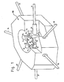
- one embodiment comprises: an optical energy transmissive body 40 such as a heptagonal prismatic bulk prism having seven side faces;. interference filters 21 to 26 provided on six predetermined side faces of the body 40; lenses 11 to 17 for the convergence or callimation of incident beams of radiant energy, attached to the filters 21 through 26 and to the remaining one side face of the body 40, respectively; optical fibers 31 to 37 provided in one-to-one correspondence to said lenses for outputing the beams given from the lenses or for coupling given beams to said lenses; and spacers 51 to 57 for setting a predetermined incident angle A with respect to each of the seven side faces of the body 40.
- an optical energy transmissive body 40 such as a heptagonal prismatic bulk prism having seven side faces
- interference filters 21 to 26 provided on six predetermined side faces of the body 40
- lenses 11 to 17 for the convergence or callimation of incident beams of radiant energy, attached to the filters 21 through 26 and to the remaining one side face of the body 40, respectively
- optical fibers 31 to 37 provided
- the filters 21 to 26, each having a multilayer structure of SiO 2 and TiO 2 , are so designed as to pass only wavelengths ⁇ 1 to ⁇ 6 , respectively.
- the structural elements 11 to 17, 21 to 26, 31 to 37, 40, and 51 to 57 are contained in a holder 100 formed of stainless steel.
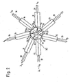
- An input beam of radiant energy provided by any suitable source such as a laser (not shown) and containing a plurality of wavelengths ⁇ 1 to ⁇ 6 , is made incident from the optical fiber 37 onto the lens 17 and collimated therein. After being transmitted through the spacer 57 and the body 40, the collimated beam is supplied to the filter 21 for passing only a beam of ⁇ 1 .
- the beam of ⁇ 1 after passing the filter 21, is converged by the lens 11 and coupled to the output fiber 31.
- the beam containing the wavelengths ⁇ 2 to ⁇ 6 is reflected by the filter 21, again transmitted through the body 40, and reach the next filter 22 for passing only a beam of ⁇ 2 .
- the beam of ⁇ 2 after passing the filter 22, is converged by the lens 12 and coupled to the fiber 32.
- the beam containing the wavelengths ⁇ 3 to ⁇ 6 is reflected by the filter 22, and, similarly, coupled through the lenses 13, 14, 15, and 16 for the beam convergence to the output fibers 33, 34, 35, and 36, respectively.
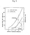
- the maximum optical path length is almost proportional to the number of wavelengths multiplexed, resulting in greater insertion loss.
- the increase in insertion loss is particularly significant where more than seven wavelengths are multiplexed.
- the maximum optical path length, over which an incident beam travels from where it enters the filter 2 1 until the beam of the wavelength ⁇ 6 contained in the incident beam is finally taken out from the filter 26, can be considerably shortened.
- the optical demultiplexer of FIG. 1, formed of the structural elements given in Table 1, has been found to have the wavelength- insertion loss relationship shown in Table 2.
- heptagonal prism is used in this embodiment to form an optical demultiplexer suited for six wavelengths
- the same heptagonal prism can be used to achieve an optical demultiplexer for any number of wavelengths between two and five inclusive.
- FIG. 1 Although the embodiment shown in FIG. 1 is described as a demultiplexer, the embodiment also operates as a multiplexer when the demultiplexer operation is reversed.
- the present invention can provide a highly reliable optical device, which can operate with extremely reduced insertion loss.
Abstract
Description
- The invention relates to an optical multiplexer/demultiplexer using interference filters.
- With the recent development and implementation of fiber optic technology into practical transmission systems, a great deal of attention has been paid to a multiple carrier technique referred to as wavelength division multiplexing (WDM). With the WDM technique resorting to an optical multiplexer/demultiplexer, a plurality of input beams of radiant energy, each having a different preselected wavelength, is combined into a single beam containing said different wavelengths therein and, conversely, the single beam combined is separated into its constituent wavelengths. In general, such an optical multiplexer/ demultiplexer may be composed of either interference filters or diffraction gratings. More specifically, the one using the former, though less steep in its penetrating wavelength characteristic than the one using the latter, can exhibit an excellent multiplexing capability over a wide range of wavelengths. Such kind of optical multiplexer/ demultiplexer using the interference filters can also provide a high reliability based on the fact that its filter characteristics can be determined independently of the parameters of the fibers used.
- An example of the optical multiplexer/demultiplexer outlined above is proposed by Kiyoshi Nosu et al. in a paper titled "Multireflection Optical Multi/Demultiplexer Using Iaterfereace Filters," published in the ELECTRONIC LETTERS, Vol. 15, No. 14, June 5, 1979, pp.414-415 (Reference). However, with this device proposed in Fig. 1 of the Reference, an appreciable amount of insertion loss must be taken into consideration in practical use, because, in operation, a wavelength- multiplexed incident beam has to travel over a long optical path of maximum length, ranging from the filter 1 to the
filter 6. - An object of the present invention, therefore, is to provide a highly reliable optical multiplexer/demultiplexer free of the foregoing disadvantage.
- Accarding to one aspect of the invention, there is provided an optical multiplexer/demultiplexer for use in a wavelength division multiplexing, which comprises: an optical energy transmission body having N side faces, N being equal to or larger than three; first means associated with a first predetermined one of said N side faces for directing a single beam of radiant energy at a predetermined angle with respect to said predetermined one side face into or out of said body for the demultiplexing or multipiexing operation, said single beam containing M preselected wavelengths, M being equal to or smaller than N-1; a plurality of second means associated in one-to-one correspondence with (M-1) side faces of said N side faces, each of said plurality of second means passing a beam containing a corresponding one of said M wavelengths and reflecting a beam containing at least one wavelength of said M wavelengths, other than said corresponding wavelength; third means associated with a second predetermined one of said N side faces for passing a beam finally reflected by said plurality of second means; -and a plurality of fourth means associated in one-to-one correspondence with said plurality of second means and said third means, each of said plurality of fourth means receiving or emanating a corresponding one of the beams passing through said second and third means for the demultiplexing or multiplexing operation.
- This invention will be described in greater detail in conjunction with the accompanying drawings, wherein:
- FIG. 1 shows a perspective view of one embodiment of the invention;
- FIG. 2 is a diagram for describing the operation of the embodiment:
- FIG. 3 is a diagram illustrating the advantages of the embodiment.
- In the drawings, like reference numerals denote like structual elements.
- Referring to FIG. 1, one embodiment comprises: an optical energy
transmissive body 40 such as a heptagonal prismatic bulk prism having seven side faces;.interference filters 21 to 26 provided on six predetermined side faces of thebody 40;lenses 11 to 17 for the convergence or callimation of incident beams of radiant energy, attached to thefilters 21 through 26 and to the remaining one side face of thebody 40, respectively;optical fibers 31 to 37 provided in one-to-one correspondence to said lenses for outputing the beams given from the lenses or for coupling given beams to said lenses; andspacers 51 to 57 for setting a predetermined incident angle A with respect to each of the seven side faces of thebody 40. Thefilters 21 to 26, each having a multilayer structure of SiO2 and TiO2, are so designed as to pass only wavelengths λ1 to λ6, respectively. Thestructural elements 11 to 17, 21 to 26, 31 to 37, 40, and 51 to 57 are contained in aholder 100 formed of stainless steel. - Next will be described in detail the demultiplexing operation of this embodiment with reference to FIGS. 1 and 2. An input beam of radiant energy, provided by any suitable source such as a laser (not shown) and containing a plurality of wavelengths λ1 to λ6, is made incident from the
optical fiber 37 onto thelens 17 and collimated therein. After being transmitted through thespacer 57 and thebody 40, the collimated beam is supplied to thefilter 21 for passing only a beam of λ1. The beam of λ1, after passing thefilter 21, is converged by thelens 11 and coupled to theoutput fiber 31. On the other hand, the beam containing the wavelengths λ2 to λ6 is reflected by thefilter 21, again transmitted through thebody 40, and reach thenext filter 22 for passing only a beam of λ2. The beam of λ2, after passing thefilter 22, is converged by thelens 12 and coupled to thefiber 32. Also, the beam containing the wavelengths λ3 to λ6, is reflected by thefilter 22, and, similarly, coupled through thelenses output fibers - As shown in FIG. 3, with the structure of Reference, the maximum optical path length is almost proportional to the number of wavelengths multiplexed, resulting in greater insertion loss. The increase in insertion loss is particularly significant where more than seven wavelengths are multiplexed. On the other hand, with the structure of the invention, the maximum optical path length, over which an incident beam travels from where it enters the filter 21 until the beam of the wavelength λ6 contained in the incident beam is finally taken out from the
filter 26, can be considerably shortened. - Furthermore, as is evident from the structure shown in FIG. 1, since the structural elements (lenses, filters, and fibers) are arranged approximately in symmetry with respect to the optical axis, which is radially extended, the forces of thermal expansion exerting over those elements are uniform with respect to the optical axis. As a result, the deviation of the optical axis due to thermal expansion is extremely reduced, enabling the achievement of a highly reliable optical device.
- The optical demultiplexer of FIG. 1, formed of the structural elements given in Table 1, has been found to have the wavelength- insertion loss relationship shown in Table 2.


- Whereas a heptagonal prism is used in this embodiment to form an optical demultiplexer suited for six wavelengths, the same heptagonal prism can be used to achieve an optical demultiplexer for any number of wavelengths between two and five inclusive.
- Although the embodiment shown in FIG. 1 is described as a demultiplexer, the embodiment also operates as a multiplexer when the demultiplexer operation is reversed.
- As hetherto described, the present invention can provide a highly reliable optical device, which can operate with extremely reduced insertion loss.
Claims (6)
Applications Claiming Priority (2)
| Application Number | Priority Date | Filing Date | Title |
|---|---|---|---|
| JP90253/81 | 1981-06-12 | ||
| JP56090253A JPS57204507A (en) | 1981-06-12 | 1981-06-12 | Interference film type optical multiplexer and demultiplexer |
Publications (2)
| Publication Number | Publication Date |
|---|---|
| EP0068198A1 true EP0068198A1 (en) | 1983-01-05 |
| EP0068198B1 EP0068198B1 (en) | 1985-12-11 |
Family
ID=13993325
Family Applications (1)
| Application Number | Title | Priority Date | Filing Date |
|---|---|---|---|
| EP82105027A Expired EP0068198B1 (en) | 1981-06-12 | 1982-06-08 | Optical multiplexer/demultiplexer using interference filters |
Country Status (5)
| Country | Link |
|---|---|
| US (1) | US4482994A (en) |
| EP (1) | EP0068198B1 (en) |
| JP (1) | JPS57204507A (en) |
| CA (1) | CA1176766A (en) |
| DE (1) | DE3267892D1 (en) |
Cited By (2)
| Publication number | Priority date | Publication date | Assignee | Title |
|---|---|---|---|---|
| GB2168825A (en) * | 1984-12-21 | 1986-06-25 | Int Standard Electric Corp | Optical coupler |
| EP0234369A1 (en) * | 1986-02-06 | 1987-09-02 | Fujitsu Limited | Optical branching filter |
Families Citing this family (44)
| Publication number | Priority date | Publication date | Assignee | Title |
|---|---|---|---|---|
| JPS61103110A (en) * | 1984-10-26 | 1986-05-21 | Hitachi Ltd | Optical multiplexer and demultiplexer |
| DE3515981A1 (en) * | 1985-05-03 | 1986-11-06 | Siemens AG, 1000 Berlin und 8000 München | LIGHTWAVE CONDUCTOR TRANSMISSION SYSTEM |
| DE3908530C1 (en) * | 1989-03-16 | 1990-08-09 | Messerschmitt-Boelkow-Blohm Gmbh, 8012 Ottobrunn, De | |
| DE4019980B4 (en) * | 1989-06-22 | 2004-01-29 | Hitachi Cable, Ltd. | Device for measuring the temperature in the longitudinal direction of a light guide sensor |
| US5002350A (en) * | 1990-02-26 | 1991-03-26 | At&T Bell Laboratories | Optical multiplexer/demultiplexer |
| US5109447A (en) * | 1991-03-04 | 1992-04-28 | The Boeing Company | High-powered, spectrally flat, very broadband optical source including optical coupler and method using same |
| GB9116942D0 (en) * | 1991-08-06 | 1991-10-09 | Marconi Gec Ltd | Optical fibre arrangement |
| DE4230224A1 (en) * | 1992-09-10 | 1994-03-17 | Bundesrep Deutschland | Beam splitting and focussing lens for laser machining system - has one or more active lens surfaces comprising partial surfaces with different beam deflection parameters |
| IL107508A (en) * | 1993-11-05 | 1996-12-05 | Orbotech Ltd | Method and apparatus for recording on optically-sensitive media |
| US5467418A (en) * | 1994-09-02 | 1995-11-14 | At&T Ipm Corp. | Frequency routing device having a spatially filtered optical grating for providing an increased passband width |
| US5812291A (en) * | 1995-03-22 | 1998-09-22 | Cselt Centro Studi E Laboratori Telecomunicazioni S.P.A. | Optical add-drop multiplexer for optical communication networks |
| US5600467A (en) * | 1995-06-14 | 1997-02-04 | Mci Communications Corp. | Method and apparatus for reducing harmonic interference on multiplexed optical communication lines |
| US5737104A (en) * | 1995-12-18 | 1998-04-07 | Dicon Fiberoptics | Wavelength division multiplexer and demultiplexer |
| US6125228A (en) * | 1998-03-04 | 2000-09-26 | Swales Aerospace, Inc. | Apparatus for beam splitting, combining wavelength division multiplexing and demultiplexing |
| US6008920A (en) * | 1998-03-11 | 1999-12-28 | Optical Coating Laboratory, Inc. | Multiple channel multiplexer/demultiplexer devices |
| US6253007B1 (en) | 1998-07-08 | 2001-06-26 | Optical Switch Corporation | Method and apparatus for connecting optical fibers |
| US6236787B1 (en) | 1998-07-08 | 2001-05-22 | Optical Switch Corporation | Method and apparatus for aligning optical fibers using an alignment spacer |
| US6137930A (en) * | 1998-07-08 | 2000-10-24 | Optical Switch Corporation | Method and apparatus for aligning optical fibers |
| US6215924B1 (en) | 1998-08-06 | 2001-04-10 | Optical Coating Laboratory, Inc. | Optical coupler device for dense wavelength division multiplexing |
| US6236778B1 (en) | 1998-12-16 | 2001-05-22 | Optical Switch Corporation | Frustrated total internal reflection bus and method of operation |
| US6243511B1 (en) | 1999-02-04 | 2001-06-05 | Optical Switch Corporation | System and method for determining the condition of an optical signal |
| JP2002022939A (en) * | 2000-07-13 | 2002-01-23 | Nippon Sheet Glass Co Ltd | Optical element having wavelength selectivity, method for manufacturing the same, and wavelength selective device |
| US6542306B2 (en) | 2001-03-16 | 2003-04-01 | Optical Coating Laboratories, Inc. | Compact multiple channel multiplexer/demultiplexer devices |
| US6636654B2 (en) * | 2001-03-30 | 2003-10-21 | Optical Research Associates | Programmable optical switching add/drop multiplexer |
| US6636658B2 (en) | 2001-04-23 | 2003-10-21 | Optical Coating Laboratory, Inc. | Wavelength division multiplexing/demultiplexing systems |
| CN100480650C (en) * | 2001-08-13 | 2009-04-22 | 浜松光子学株式会社 | Spectrally separating apparatus and method |
| US7203421B2 (en) * | 2001-09-28 | 2007-04-10 | Optical Research Associates | Littrow grating based OADM |
| WO2003089966A2 (en) * | 2002-04-18 | 2003-10-30 | Cierra Photonics, Inc. | Wavelenght selective fiber optic coupler |
| WO2003107045A2 (en) * | 2002-06-12 | 2003-12-24 | Optical Research Associates | Wavelength selective optical switch |
| WO2004010175A2 (en) * | 2002-07-23 | 2004-01-29 | Optical Research Associates | East-west separable, reconfigurable optical add/drop multiplexer |
| US7522790B1 (en) * | 2002-12-20 | 2009-04-21 | Raytheon Company | Optical communications system with selective block/add capability of an optical channel |
| US7072540B1 (en) | 2003-04-22 | 2006-07-04 | Raytheon Company | Method of assembling a multiplexer/demultiplexer apparatus to account for manufacturing variations in the thin-film optical filters |
| US20060088255A1 (en) * | 2004-10-22 | 2006-04-27 | Enboa Wu | Multi-wavelength optical transceiver subassembly module |
| EP2769260B1 (en) * | 2011-10-20 | 2019-09-04 | Acea Biosciences, Inc. | Device for splitting light into components having different wavelength ranges and methods of use |
| US9568423B2 (en) | 2011-10-21 | 2017-02-14 | Acea Biosciences, Inc. | System and method for detecting multiple-excitation-induced light in a flow channel |
| US9746412B2 (en) | 2012-05-30 | 2017-08-29 | Iris International, Inc. | Flow cytometer |
| JP2015525343A (en) | 2012-05-30 | 2015-09-03 | アイリス インターナショナル インコーポレイテッド | Flow cytometer |
| US10261080B2 (en) | 2013-11-19 | 2019-04-16 | Acea Biosciences, Inc. | Optical detection system for flow cytometer, flow cytometer system and methods of use |
| US9575063B2 (en) | 2013-11-19 | 2017-02-21 | Acea Biosciences, Inc. | Optical engine for flow cytometer, flow cytometer system and methods of use |
| CN105940292B (en) | 2013-12-04 | 2020-12-08 | 艾瑞斯国际有限公司 | Flow cytometer |
| US9869628B2 (en) | 2014-06-25 | 2018-01-16 | Acea Biosciences, Inc. | Methods of collecting cells from multi-well plates for use in flow cytometry |
| CN109844449B (en) * | 2016-07-25 | 2021-11-16 | 厦泰生物科技公司 | Flow cytometer |
| FR3060248B1 (en) * | 2016-12-09 | 2019-03-15 | Safran Electrical & Power | OPTICAL RING OPERATED COMMUNICATION NETWORK FOR AIRCRAFT |
| CN114236716B (en) * | 2022-02-28 | 2022-05-17 | 耀芯电子(浙江)有限公司 | Single-fiber bidirectional multimode wavelength division multiplexing photoelectric conversion device and manufacturing method thereof |
Family Cites Families (2)
| Publication number | Priority date | Publication date | Assignee | Title |
|---|---|---|---|---|
| JPS54103055A (en) * | 1978-01-31 | 1979-08-14 | Nippon Telegr & Teleph Corp <Ntt> | Spectrometer |
| EP0004408B1 (en) * | 1978-03-27 | 1981-11-11 | Shell Internationale Researchmaatschappij B.V. | A process for preparing 1,7-octadiene and for activating a catalyst suitable for use in the process |
-
1981
- 1981-06-12 JP JP56090253A patent/JPS57204507A/en active Pending
-
1982
- 1982-06-07 US US06/385,474 patent/US4482994A/en not_active Expired - Lifetime
- 1982-06-08 DE DE8282105027T patent/DE3267892D1/en not_active Expired
- 1982-06-08 EP EP82105027A patent/EP0068198B1/en not_active Expired
- 1982-06-11 CA CA000404944A patent/CA1176766A/en not_active Expired
Non-Patent Citations (3)
| Title |
|---|
| EDN MAGAZINE, vol.26, no.3, February 1981, Boston, Mass. (US), T. ORMOND: "Wavelength multiplex, demultiplex devices emerge from fiber-optic research", pages 73-74 * |
| ELECTRONICS LETTERS, vol.15, no.14, July 5, 1979, K. NOSU: "Multirflection optical multi/Demultiplexer using interference filters", pages 414-415 * |
| OPTICS LETTERS, vol.5, no.7, July 1980, Optical Society of America, New York (US), E. MIYAUCHI et al.: "Compact wavelength multiplexer using optilcal-fiber pieces", pages 321-322 * |
Cited By (3)
| Publication number | Priority date | Publication date | Assignee | Title |
|---|---|---|---|---|
| GB2168825A (en) * | 1984-12-21 | 1986-06-25 | Int Standard Electric Corp | Optical coupler |
| EP0234369A1 (en) * | 1986-02-06 | 1987-09-02 | Fujitsu Limited | Optical branching filter |
| US4824200A (en) * | 1986-02-06 | 1989-04-25 | Fujitsu Limited | Optical branching filter |
Also Published As
| Publication number | Publication date |
|---|---|
| EP0068198B1 (en) | 1985-12-11 |
| DE3267892D1 (en) | 1986-01-23 |
| CA1176766A (en) | 1984-10-23 |
| JPS57204507A (en) | 1982-12-15 |
| US4482994A (en) | 1984-11-13 |
Similar Documents
| Publication | Publication Date | Title |
|---|---|---|
| EP0068198A1 (en) | Optical multiplexer/demultiplexer using interference filters | |
| EP0390416B1 (en) | Optical multiplexer/demultiplexer using focusing bragg reflectors | |
| US4244045A (en) | Optical multiplexer and demultiplexer | |
| US4335933A (en) | Fiber optic wavelength demultiplexer | |
| US6169828B1 (en) | Fiber optic dense wavelength division multiplexer with a phase differential method of wavelength separation utilizing a polarization beam splitter and a nonlinear interferometer | |
| CA2237319C (en) | Device for focusing light through an optical component | |
| US20020181048A1 (en) | Method and system for high channel capacity wave division multiplexer and de-multiplexer using reflective and transmission holographic methodologies for optical communications and the like | |
| JPS61212805A (en) | Reverser for separating a plurality of light signals in optical integration | |
| US20020181046A1 (en) | Wavelength division multiplexing with narrow band reflective filters | |
| US4723829A (en) | Optical wavelength demultiplexer | |
| JPH10300976A (en) | Optical fiber wavelength multiplexer and demultiplexer | |
| US6125228A (en) | Apparatus for beam splitting, combining wavelength division multiplexing and demultiplexing | |
| GB2046941A (en) | Optical waveguide branching device | |
| US6188817B1 (en) | Photonics system | |
| US6246812B1 (en) | V-groove dual fiber collimator for DWDM multiplexor/demultiplexor | |
| CA1257415A (en) | Optical multiplexer/demultiplexer | |
| JPS6161107A (en) | Optical multiplex separation transmitter | |
| WO2000025162A3 (en) | Multiple port, fiber optic coupling device | |
| US4589724A (en) | Multiple branching light wave guide element | |
| US7031610B2 (en) | Diffraction-compensated integrated WDM | |
| JP2001281493A (en) | Wavelength demultiplexing and multiplexing module | |
| CN111965762A (en) | Grating wavelength division multiplexing device | |
| US20040042719A1 (en) | Optical device for compensation of multiple wavelengths and working distances in dual-fiber collimators | |
| US7194161B1 (en) | Wavelength-conserving grating router for intermediate wavelength density | |
| JPS6046682B2 (en) | Optical multiplexing/demultiplexing circuit for optical beams |
Legal Events
| Date | Code | Title | Description |
|---|---|---|---|
| PUAI | Public reference made under article 153(3) epc to a published international application that has entered the european phase |
Free format text: ORIGINAL CODE: 0009012 |
|
| AK | Designated contracting states |
Designated state(s): DE FR GB NL |
|
| 17P | Request for examination filed |
Effective date: 19821230 |
|
| RAP1 | Party data changed (applicant data changed or rights of an application transferred) |
Owner name: NEC CORPORATION |
|
| GRAA | (expected) grant |
Free format text: ORIGINAL CODE: 0009210 |
|
| AK | Designated contracting states |
Designated state(s): DE FR GB NL |
|
| ET | Fr: translation filed | ||
| REF | Corresponds to: |
Ref document number: 3267892 Country of ref document: DE Date of ref document: 19860123 |
|
| PLBE | No opposition filed within time limit |
Free format text: ORIGINAL CODE: 0009261 |
|
| STAA | Information on the status of an ep patent application or granted ep patent |
Free format text: STATUS: NO OPPOSITION FILED WITHIN TIME LIMIT |
|
| RIN2 | Information on inventor provided after grant (corrected) |
Free format text: ISHIKAWA, SHIGETA |
|
| 26N | No opposition filed | ||
| PGFP | Annual fee paid to national office [announced via postgrant information from national office to epo] |
Ref country code: GB Payment date: 19960605 Year of fee payment: 15 |
|
| PGFP | Annual fee paid to national office [announced via postgrant information from national office to epo] |
Ref country code: FR Payment date: 19960607 Year of fee payment: 15 |
|
| PGFP | Annual fee paid to national office [announced via postgrant information from national office to epo] |
Ref country code: NL Payment date: 19960630 Year of fee payment: 15 |
|
| PGFP | Annual fee paid to national office [announced via postgrant information from national office to epo] |
Ref country code: DE Payment date: 19960829 Year of fee payment: 15 |
|
| PG25 | Lapsed in a contracting state [announced via postgrant information from national office to epo] |
Ref country code: GB Free format text: LAPSE BECAUSE OF NON-PAYMENT OF DUE FEES Effective date: 19970608 |
|
| PG25 | Lapsed in a contracting state [announced via postgrant information from national office to epo] |
Ref country code: NL Effective date: 19980101 |
|
| GBPC | Gb: european patent ceased through non-payment of renewal fee |
Effective date: 19970608 |
|
| PG25 | Lapsed in a contracting state [announced via postgrant information from national office to epo] |
Ref country code: FR Free format text: LAPSE BECAUSE OF NON-PAYMENT OF DUE FEES Effective date: 19980227 |
|
| NLV4 | Nl: lapsed or anulled due to non-payment of the annual fee |
Effective date: 19980101 |
|
| PG25 | Lapsed in a contracting state [announced via postgrant information from national office to epo] |
Ref country code: DE Free format text: LAPSE BECAUSE OF NON-PAYMENT OF DUE FEES Effective date: 19980303 |
|
| REG | Reference to a national code |
Ref country code: FR Ref legal event code: ST |
|
| REG | Reference to a national code |
Ref country code: FR Ref legal event code: ST |